DIY Solid State Tesla Coil
A Simple DIY Solid State Tesla Coil
This Solid State Tesla Coil is easy to build, upgradeable and gives great results with only a a little work! This project shows how to make a small Tesla Coil that can run on batteries or any other suitable low voltage DC supply. From as little as 12V input it is possible to make high frequency plasma sparks that even play music! The result of this high voltage, high frequency output is being able to make awesome looking sparks and arcs of plasma in the air.
![]() WARNING: High Voltage Device! High Voltages can be very dangerous!
WARNING: High Voltage Device! High Voltages can be very dangerous!
What is an SSTC (Solid State Tesla Coil)?
What it is and how it differs from a classical Tesla Coil (SGTC) which uses a spark gap.
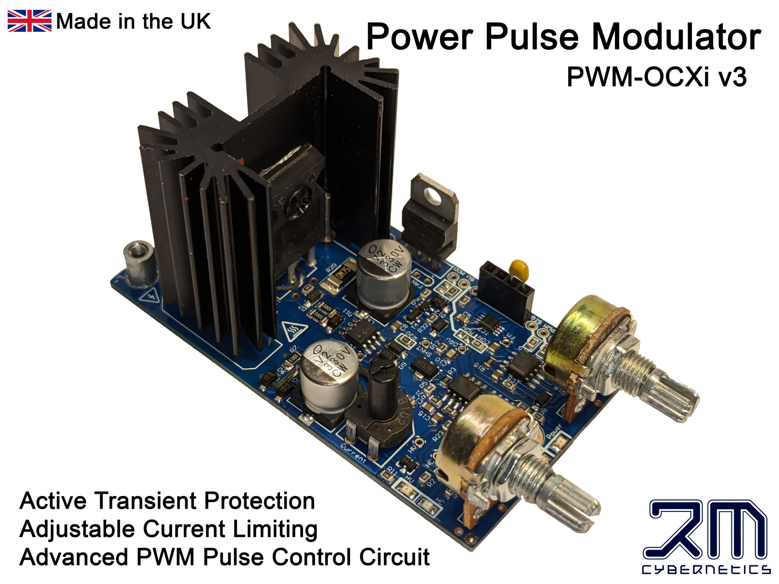
Like all Tesla Coils, a Solid State Tesla Coil (SSTC) is a type of high frequency resonant transformer which can step up a low voltage DC input into a very high frequency AC output. The main difference between a SSTC vs a SGTC is that the SSTC has no spark gap an instead uses modern transistor technology to switch the current in the primary coil. If you are not familiar with them, check our article on how a Tesla Coil works. There are many forms of SSTC which vary by how the transistors are configured or how the system is resonated. In this version, just a single IGBT is used to switch current in the primary at the resonant frequency of the secondary coil. By using a specialised PWM circuit (our Power Pulse Modulator PWM-OCXi v2) it is possible to tune into the right frequency and then adjust the power level with the turn of a knob.
There are a lot of articles online showing how to make an SSTC, but we like to think that this one must be one of the simplest and most cost effective ways of making one and without compromising on performance.

 How to make an SSTC
How to put the parts together to make a SSTC
If you choose to buy all the parts ready made then it is possible to get this Tesla Coil up and running in around five minutes! Only a few parts are required for this SSTC. These are detailed below along with how to put them together in a number of ways to make a simple mini solid state Tesla Coil.
For this project, you will need;
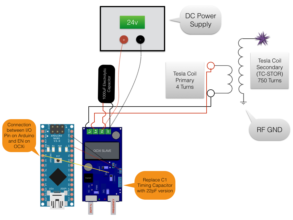
• Power Pulse Modulator PWM-OCXi v2 (Though it is feasible with only one OCXi, you will get a more stable and prolonged effect result with two!)
• A PSU with a voltage between 12V and 30V with a current of at least 5A. A large battery could also work, but take care not to let the voltage drop below 12V.
• A helical coil of around 750 turns (for the secondary coil)
• 10A (or larger) cable for winding primary coil
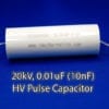
• A 1000uF, 50V (or more) electrolytic capacitor
• A 22pF timing capacitor (for the OCXi)
The Secondary Coil
The tall helical coil from which the sparks come
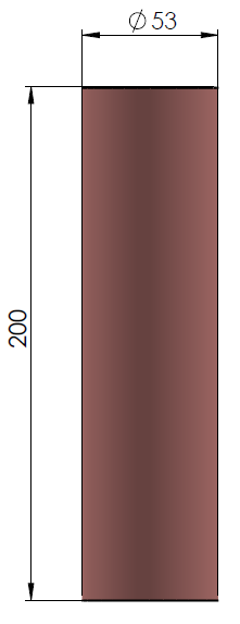 This part can be quite difficult and time consuming to produce yourself. If you do not want to wind your own, check out our helical coils or Tesla Coil Secondary coils which include a toroid. The exact size or number of windings are not critical as long as there is a relatively high number of turns on the secondary coil. Our coils use around 750 turns of 0.25mm magnet wire wound onto a PVC pipe of 53mm in diameter. This coil resonates at around 1MHz.
To make one yourself, find a suitable piece of pipe such as some drainage pipe or any other straight plastic tube that is around 20cm long. Start by fixing the start of your wire to one end of the coil then carefully turn the tube while holding the wire tight so that each turn lays right up against the previous turn. It is important to make all the turns tight and with no spaces or overlapping turns otherwise the coil may not operate efficiently. During winding it can be useful to add a small spot of super glue occasionally so that if you accidently let go, it wont all unwind and leave you with a tangled mess. When using magnet wire (enamel coated wire), it is necessary to scrape off the insulating layer at the ends so that a connection can be made. While this is not so important at the output side, it is essential at the base where there must be a good connection to RF ground.
The HV output will come from the top part of the coil. You should let a small bit of wire protrude away from the main body of the coil so that the electric field will be concentrated around it’s tip. The bottom of the coil must be connected to a suitable RF (radio frequency) Ground. This should not mains ground, or the GND connection of your power supply. This is because the high frequency can cause significant interference with other electronics. A suitable RF GND would be a connection to a metal filing cabinet, or a long metal stake in the earth.
The Primary Coil
Small coil pulsed with low voltage, high current
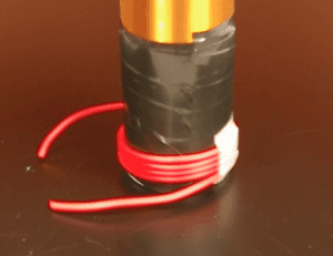 The primary coil simply consists of around four windings of thick copper wire wrapped around the base of the secondary coil. It is best to use something well insulated as it prevents corona leaking energy from the primary coil. In this example we used 10A silicone insulated wire as it is highly flexible, well insulated and easy to work with. Before coiling the primary winding onto the secondary coil, we wrapped a folded piece of A4 paper around the bottom and then coated the paper with insulating tape. This just helps to protect the fine secondary windings and also reduce corona leakage.
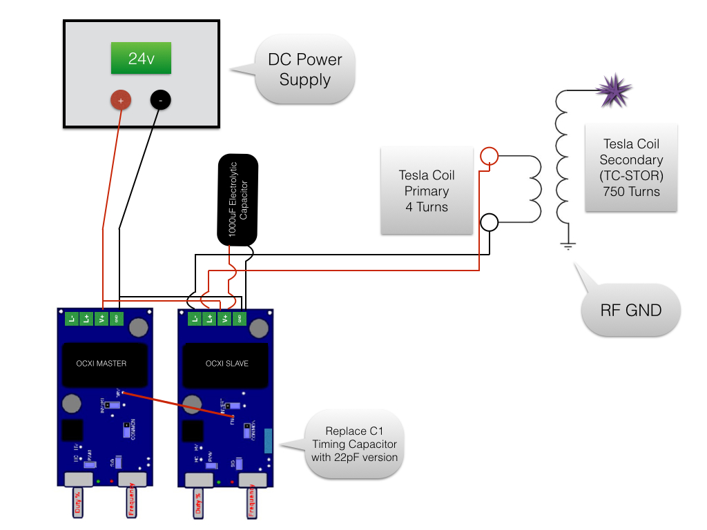
The ends of the primary coil connect directly to the PWM-OCXi’s output terminals (L+ and L-). The length of connecting wire between the OCXi and the base of the coil should be around 10cm. If it is too long, the extra inductance and resistance might reduce the performance of the SSTC.
 The SSTC Drive Circuit
Connecting the PWM-OCXi to the primary coil and PSU
It is possible to just use a single OCXi drive circuit to make this work, but this will run the SSTC at a continuous 1MHz. While this will make a great silent plasma plume, it is really hard work for the IGBT in the circuit which means it will quickly heat up and could be damaged if allowed to get too hot. When used in this way it is sometimes refered to as a Continuous Wave SSTC (CWSSTC) due to the fact that the output is a continuous 1MHz high voltage waveform.
It is best to use one OCXi tuned to power the primary coil at 1MHz and then another OCXi (or another low frequency source) to modulate its output. By doing this we can make short 1MHz pulses that create a large spark while not dissipating too much heat over time in the IGBT on the OCXi drive circuit. The OCXi driving the coil will need to have the timing capacitor (C1) replaced with one rated for 22pF so that the frequency range is at the top end.
The diagram shown here shows two OCXi circuits in a Master/Slave setup. The circuits are powered from the same supply and a short wire is connected between the master’s DRV connection and the slave’s EN connection. More details about the master/slave setup can be found in the OCXi datasheet. The slave device is set to power the primary coil at 1MHz with around 50% duty, while the master OCXi is set to around 100Hz and 10% duty. Each time the master OCXi pulses high, the slave circuuit is momentarily activated. The resultant sparks look as good as they would with only one OCXi, but at only 10% of the power used!
It is important to connect a large capacitor such as a 1000uF 50V electrolyitic capacitor close to the power input terminals of the circuit driving the primary coil. This is used to help supply the high current pulses to the coil as a PSU or battery would not be able to do this alone.
![]() DANGER: This device will create a lot of radio frequency interference!
DANGER: This device will create a lot of radio frequency interference!
Operating the Solid State Tesla Coil
Tuning and running the SSTC
First of all make sure it is set up in a clear space, and it is not near any sensitive electronics. This can cause a lot of interference with nearby electronics such as computers and phones. When doing this project, one of our computer screens around 10m away from the system would flicker when it was running! It would also cause significant problems when trying to make footage of this on our DSLR camera. Interference would reset the camera, or even corrupt the memory cards.
Before powering on the circuits, ensure that the duty setting of the slave OCXi is set to 0% while the frequency is set to maximum. If also using a slave circuit, set its duty to about 10% and the frequency to minimum.
Turn down the lights and then turn on the power to the circuits and slowly turn up the duty on the slave unit to around 50%. Watch the tip of the secondary winding for any glowing purple discharge and SLOWLY adjust the frequency control on the slave circuit until you get the biggest discharge you can. While doing this be make sure you regulary power off the system and check that the heatsink is not getting too hot on the OCXi. You may also notice that simply moving your hand near the circuit or secondary coil will alter the size of the glowing output. This is because moving near it actually alters the systems resonant frequency and therefore detunes if from what you have set on the controls.
Once satisfied with frequency the tuning, adjust the duty settings and frequency of the master circuit to give the desired effect.
 Making a Plasma Speaker
Making music come from the sparks of your SSTC!
The plasma at 1MHz makes almost no sound as 1MHz is well above the audiable range of human ears. When we modulate this frequency with another circuit, we are able to hear the frequency of that modulation. The sound comes from the air expanding around the plasma as it forms during each pulse. We can take advantage of this effect to make the SSTC play music without any speakers at all!
In this example we use an Arduino Nano (programmable circuit) loaded with some code meant to play music on a small speaker. Rather than connecting the output to a speaker, we connect it to the EN connection of the slave OCXi. Doing this causes the Tesla Coil plasma to be modulated at whatever frequency the music is.
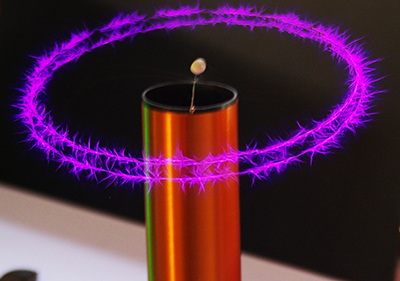 In the videos you can also see a spinning “corona motor". This is made by simply bending a thin wire into an S shape and making a small loop in the middle so it can be hooked onto a supporting wire. As the plasma forms at the sharp tips of the wire, the air is heated and pushed away giving it some thrust. This will eventually cause the whole wire to spin quite quickly and give this cool looking effect!
 The primary inverter consists of a
 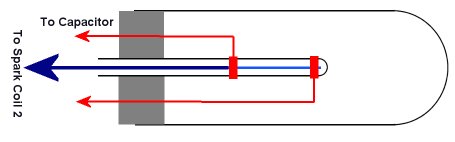 The high speed flash tube consists of two main electrodes on the outside of a small glass tube, plus a third electrode inside the glass tube so that it is isolated from the others.
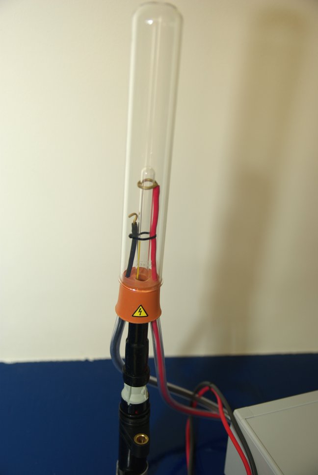
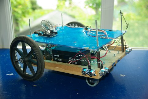 This article will cover the initial stage of creating a system so that the robot will be able to get around and avoid obstacles. This requires a basic system for motor control, and also for reading and interpreting sensor information. The processing for this will be done using an Arduino Uno which is an open source electronics prototyping platform using an ATmega328 micro-controller. This has the advantage of being simple to program and interface with. There are also many code libraries available on the Internet which people have shared for making programming of common tasks even more simple.
 The chassis for this robot is quite large and heavy because we intend to add much more to it later. This weight meant that the wheels should not be directly connected to the gearbox output shaft on the motor. Instead they were mounted on separate axles with a couple of bearings so that the weight is taken by them instead of the motor. If you want to replicate this part of the project, it could be done with a tiny robot as the Arduino and sensors are very small and lightweight.
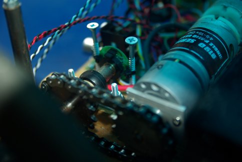 To the end of each axle is a rotary encoder. It was originally fitted to the motors shaft, but at a count of 64 pulses per turn, and a gearbox of 148:1, we felt that 9472 pulses per turn of the wheel was an unnecessary overhead for the small processor. The encoders were instead placed directly on the axle so that it would give 64 pulses per wheel rotation.
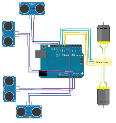 The robot is powered by two 12V SLA batteries. One battery supplies power to the control electronics, while the other is used to power the actuators (motors). By having separate batteries, the high drain from the motor will not interfere with the accuracy of the sensors and control system. The battery for the control electronics feeds into a pair of voltage regulators (5V and 12V) so that the control electronics and sensors have the right voltage levels sent to them.

 How Does Induction Heating Work?
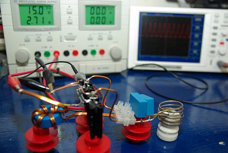 The Circuit
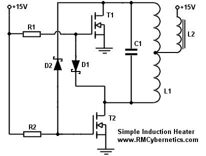 From this schematic of the induction heater you can see how simple it really is. Just a few basic components are all that is needed for creating a working induction heater device.
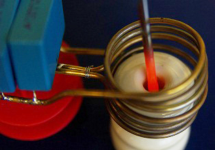
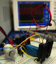 The inductor L2 is used as a choke for keeping the high frequency oscillations out of the power supply, and to limit current to acceptable levels. The value of inductance should be quite large (ours was about 2mH), but also must be made with thick enough wire for carrying all the supply current. If there is no choke used, or it has too little inductance, the circuit might fail to oscillate. The exact inductance value needed will vary with the PSU used and your coil setup. You may need to experiment before you get a good result. The one shown here was made by winding about 8 turns of 2mm thick magnet wire on a toroidal ferrite core. As an alternative you can simply wind wire onto a large bolt but you will need many more turns of wire to get the same inductance as from a toroidal ferrite core. You can see an example of this in the photo on the left. In the bottom left corner you can see a bolt wrapped with many turns of equipment wire. This setup on the breadboard was used at low power for testing. For more power it was necessary to use thicker wiring and to solder everything together.
 The Induction Coil and Capacitor


 Ceramic Standoff
 Current Meter
 12V 15A Power Supply
 12V Water Pump
 Choke
Choke Cooling Radiator
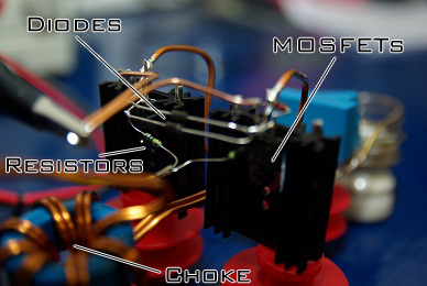
 35A 100V Transistors
 Silicone Pipe
 TO-220 Heatsink
 240 ohm Resistors
 Fast Diodes
 Polypropelene Capacitors
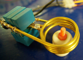 Pushing it Further
 The induction coil was made in two halves as shown here. They were then soldered together and a small piece of pvc pipe was used to connect the central pipes so that water could flow through the whole coil.
 The cables connecting to the coil were just soldered onto the pipe near the ends, just leaving room for fitting some PVC pipe.
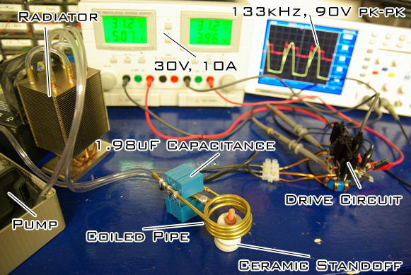 This modified CPU cooler was very effective as a radiator and allowed the water to remain quite cool.
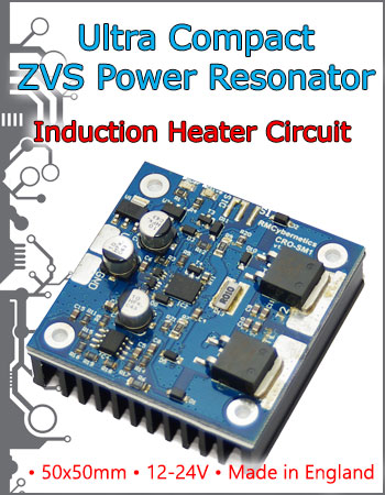
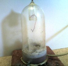 This is very simple to construct, and is made from low cost materials. The main chamber its self is the display case from a popular aftershave.
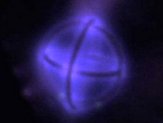 This image shows the centre electrode of an asymmetrical dipole. This arrangement allows particles to be accelerated to a central point from all directions and is often used in experimental fusion rectors. Advance fusion reactors use toroidal (dohnut shaped) vacuum chambers known as a Tokamak
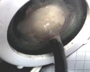
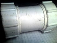 This underwater camera is made by housing a small security camera inside a pressure tight container. This setup will work perfectly in clear water, but with increased water turbidity, lights will be necessary to improve performance. Construction details for the lights and housing are shown below.
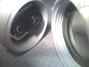
 The two end caps are not fully closed. This allows a small perspex window to be added for the camera to see through. A perspex disc should be cut to fit neatly inside the cap with an o-ring either side. PTFE tape wrapped around the screw thread will ensure a tight fit when screwing on the caps.
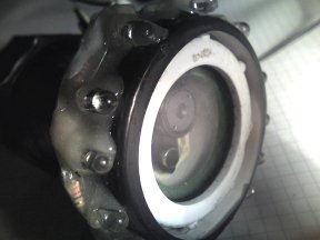
 The light source is an array of bright LED’s. The LED’s shown here are from surplus parts and are not the most effective light source for a camera. The best LEDs would be either white or infra red, as the camera will respond best to these. The LEDs and resistors were mounted on a plastic strip which is formed into a ring to fit over the end of the camera housing. They are sealed using Polymorph and epoxy resin.
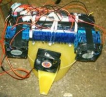 This device utilises the cooling effect of
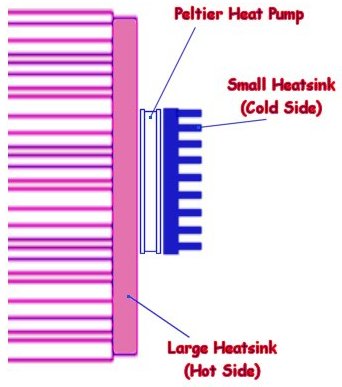
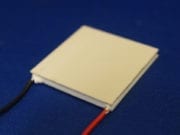
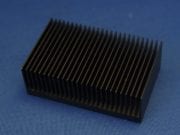
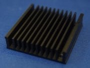
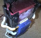
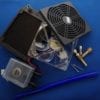
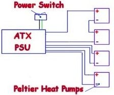 The device works by cooling the small blue heatsinks in the centre of the image. These are cooled to about 0 degrees Celsius (dependent on ambient temperature) which causes water to condense on the fins. When enough water has built up between the fins it will drip into the container below. The fan at the front simply keeps the air flowing over the cold fins, whereas the other fans are used to remove the heat from the heat pumps. In this image you can see a heat pump (peltier module) between the hot and cold heatsinks. Although this device is a useful demonstration of scientific principles, it is actually not incredibly practical or efficient.
 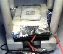 The aim of this project was to create a simple device capable of keeping components as cool as possible using common parts and materials. The device shown here is capable of maintaining a temperature of approximately -50° C.


