DIY Plasma Gun II
DIY Plasma Gun II
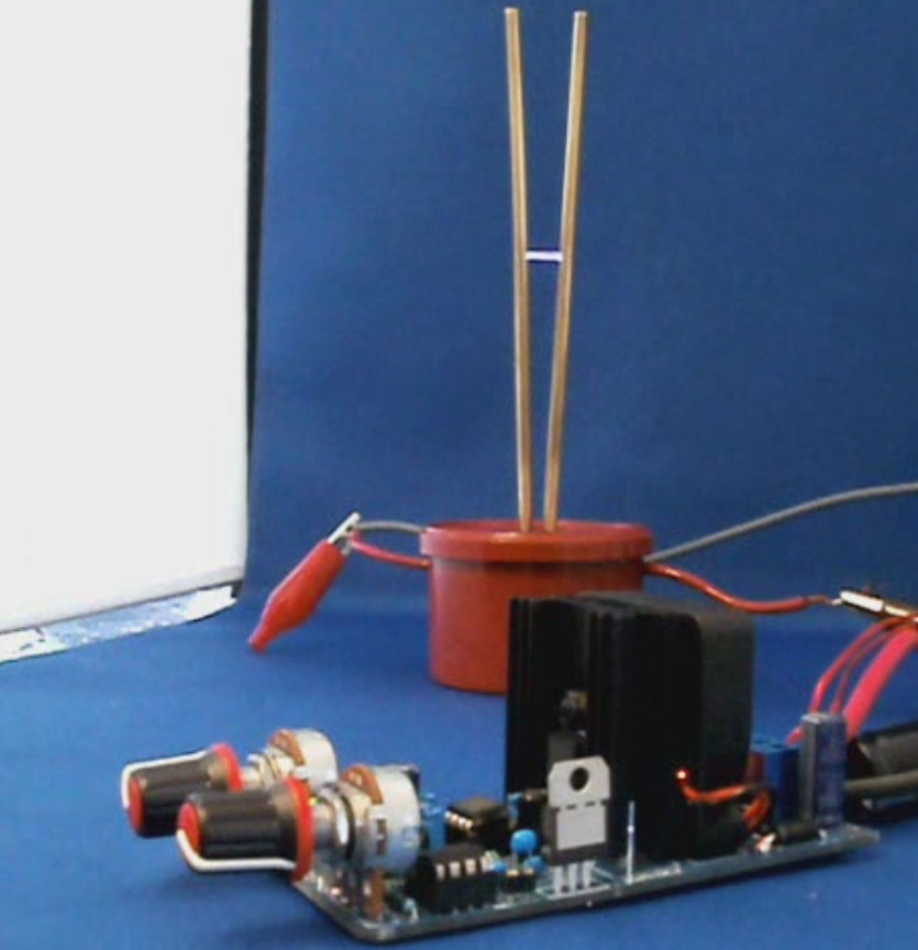
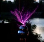
The DIY Plasma Gun II is an improved version of a compact, portable, spark gap Tesla coil which can create jets of high voltage plasma and even doubles as a flame thrower! This updated version of our hand held Tesla Coil has been optimized for improved efficiency and gives a larger output than the previous one. It is also now even easier to build! You can find the old version on the original Plasma Gun page. We decided to stick to a spark gap type Tesla Coil for this plasma gun as it is considerably easier to build and more reliable than solid state controllers. We will however produce a solid state version in future.
This page should show you all you need to know about how to make a plasma gun like the one shown here. Hopefully it will also teach you the science behind it so that you will know how it works. Remember that this is a dangerous high voltage project and should not be attempted by inexperienced people.

What does the Plasma Gun do?
This plasma gun is essentially a small battery powered spark gap Tesla coil. Its inteded purpous is more for education, than an actual function. We hope that is is a fun and interesting project and that you will learn something from it. If you make your own plasma gun, please post a picture below!
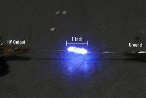
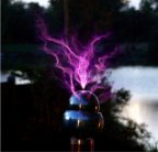
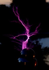
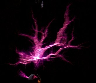
The plasma is made by ionizing air around the output terminal of the Tesla coil. The high frequency, high voltage electricity is able to form streams of plasma that can be made to spread out, or be directed forward along a flame or stream of gas. This directed plasma channel can actually have a useful function in some industrial processes known as “plasma surface treatment". When the jet of plasma is directed at a surface such as a plastic bottle, subtle changes will occur in the structure of the material on a very thin surface layer. Typically these changes will make the surface more porous, or easier to print onto.
Anyway, enough of that, we know you really want it just becasue it’s cool, and you want to build your own plasma gun! On to how it’s made…
![]() Warning: This project involves dangerous high voltage electricity!
Warning: This project involves dangerous high voltage electricity!
How it’s made
High Voltage Inverter
For converting the low battery voltage into high voltage for charging the primary capacitor.
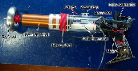
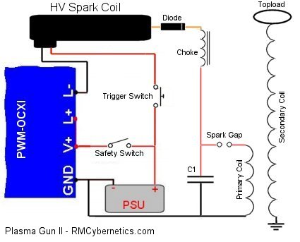
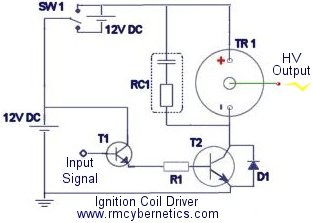
This part of the plasma gun does the main power conversion by pulsing a high voltage ignition coil. Pulsing the spark coil will step up the voltage from the battery to about 20kV which is used to charge the main capacitor. This capacitor is later discharged into the primary coil of a Tesla Coil to further increase the voltage.
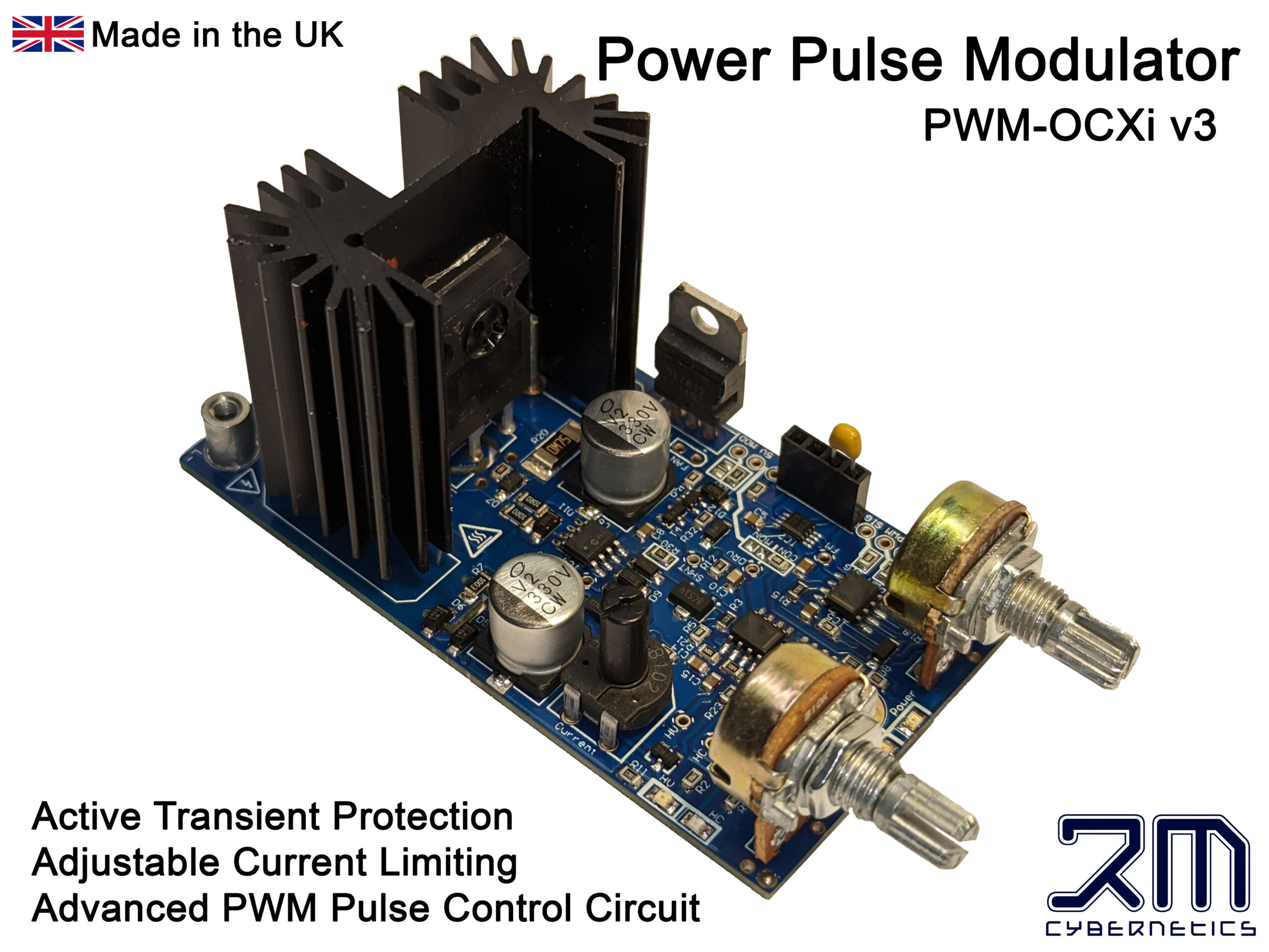
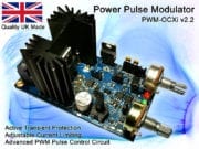
For this we used a Power Pulse Modulator (PWM-OCXI) as it is really simple to use and will give a really powerful high voltage output from an ignition coil. The PWM-OCXI is considerably more powerful than the PWM-OC10A which was used in the original plasma gun project and therefore improves power throughput significantly. This circuit was mounted in the back end of a cordless drill casing so that the control pots and LEDs were accesable from the back. At the side of the drill casing a small switch was mounted that could be used to switch the circuit on and off. This serves as a safety to power down the plasma gun when not in use.
 The power to the ignition coil was fed directly from the drill battery via the original trigger switch, into the L- connector on the OCXI. By connecting like this, the control circuit and its cooling fan stays active between times when the plasma gun is fired.
It is neccesary to add a high voltage diode to the output of the ignition coil so that a capacitor can be charged. For this, the rubber end of the ignition coil was removed, and the diode connected to the spring inside the tip. The tip was then filled with epoxy resin so that the high voltage would not flash over the body of the diode. This also helps to cool the diode by absorbing heat from it. The cathode wire is left protruding from the resin so that it can be connected to a small inductor. This inductor serves as a choke to protect the diode from the high frequency currents in the primary circuit.
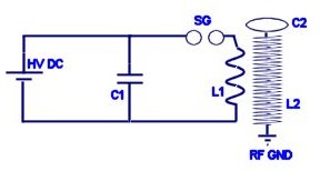
Primary Tank Circuit
For storing energy in a resonant circuit to be rapidly discharged in pulses.
The primary tank circuit here consists of a high voltage capacitor, spark gap, and a coil of wire (an inductor) known as the primary coil. When the capacitor becomes charged to a high enough voltage, the air between the terminals of the spark gap will break down with a loud bang and a bright flash. During this very brief flash, the energy in the capacitor will be moved into the primary coil and then back again over and over at about 1,000,000 times per second! This frequency of 1MHz is determined by the sizes of the capacitor and the coil and is know as the resonant frequency. The resonant frequency of this inductor capacitor combination can be calculated as follows;
Primary Circuit Resonant Frequency
f = 1 / (2 x π x √(L x C)) = 1,000,000 Hertz
Where f = Resonant frequency, L = Inductance and C = Capacitance
The value of the capacitor is fixed, and the inductance of the primary coil is determined by its size and the number of turns of wire used to make it.
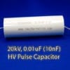
The capacitor used was chosen for improved efficiency over the ceramic capacitors used in the original Plasma Gun. By using a quality polypropelene capacitor with a low ESR and low ESL, the losses in the high frequency resonant circuit are reduced significantly. This means more awesome sparks!
When choosing the values for the components a number of factors must be considered. Some factors are fixed, while others can be varied. The table below details some of the points which must be considered.
| Parameter | Notes |
| Physical Size | The physical size was chosen to be limited to something that can be held in the hand like a gun. This size limit means that the secondary coil of the Tesla Coil must either have relatively few turns, or must use very thin wire so that more turns can fit on the form. The power supply will be limited due to size, so it is important to choose a powerful battery. |
| Secondary Coil | The design of this coil determines the resonant frequency of the diy plasma gun and therefore will limit your options for other parts in the circuit. Thin wire would cause losses due to resistance, while thicker wire will mean less turns and therefore a higher resonant frequency. |
| Resonant Frequency | The size constraint means that the resonant frequency will be relatively high. Such high frequency will cause more losses and increased impedance. It also means that a large primary voltage is needed to get a good current to flow in the primary circuit. |
| Primary Circuit | The primary circuit needs to be adjustable so that it can be tuned to match the secondary coil’s resonant frequency. Without proper tuning the plasma gun will not give a good output spark. |
Secondary Coil
Self resonant circuit which magnifies the primary voltage so that it can discharge as plasma streams.
By using 0.25mm wire there is a reasonable amount of copper for conducting current through the coil but due to the small size, only 750 can be fit onto the coil. Without a discharge terminal (topload), the resonant frequency is around 1100kHz. Such a high frequency introduces losses so we can reduce this frequency by adding a larger topload. The toroid used brings it down to a more reasonable 900kHz.
Due to the high electrical stresses, it is important to insulate the coil well with multiple layers of varnish. Although this introduces more dielectric losses, it is essential for preventing sparks flashing over the surface of the coil and for protecting the windings.
Breakout Electrode
For concentrating the electrical discharge in a focused place.
By using a large topload, the electrical field is spread over a large area and will not break out in to arcs until the voltage is very high. While this is advantageous for increasing arc length, it also increases the chances of the arc discharging back towards the coils. The breakout point creates a localised area of intense electric field which will ionise the air more easily and force the discharge away from the end of the plasma gun.
The electrode is fitted with a pipe so that gas can be ejected from the the tip. Some gasses such as Argon or Carbon Dioxide will ionise more easily than air. When ionised it will provide a conductive path, allowing the plasma to reach further from the coil. If butane is used as the gas, it will ignite and also conduct the electric currents. One difficulty with this is that as the arc length increases, it lowers the resonant frequency of the secondary coil causing it to drift away from the resonant frequency of the primary circuit.
| PARTS LIST: You can buy most of the parts from us directly. You will also need other parts such as the drill. Below is a list of parts available in our shop. | |
| Power Pulse Modulator (PWM-OCXI) | |
| 1000uF Power Capacitor | |
| HV Pulse Capacitor (20kV, 10nF) | |
| HV Spark Coil | |
| HV Diode (30kV, 100mA) | |
| Choke (390uH) | |
| Small Bolt (for choke core) | |
| Adjustable Spark Gap | |
| Silicon Cable (for primary coil and other wiring) | |
| Secondary Coil | |
| Toroid | |
| HV Insulators |
Tuning
Precise tuning of the resonant circuits for max output.
There are two resonant circuits in the Tesla coil part of the plasma gun which must be tuned to the same frequency. If the frequencies are not matched, the energy transfer will be very poor and your plasma gun will be little more than a noisy spark gap. The secondary coil’s resonant frequency is pretty much fixed. It is possible to make small adjustments by changing the size of the topload, but this is not very practical to do. Instead, it is simpler to choose a primary capacitor, and then adjust the number of turns of the primary coil to get the right resonant frequency. This can be done with a little calculation and then trial and error, but can be quite time consuming.
We used a signal generator and osciliscope for tuning the plasma gun, but it is possible to do it with a little circuit such as a Telsa Coil Tuner although it is not easy. Even after tuning, you may want to tweak the number of turns on the secondary coil to achieve maximum output. When tuning the secondary, keep it away from yourself or other objects as the proximity may alter the resonant frequency.
Once tuned you can also adjust the Power Pulse Modulator so that you get some good resonant charging of the capacitor. At certain frequencies the system will be more efficient o by slowly adjusting the frequency when it is running, it is possible to find the best setting. While making the adjustments, the spark gap firing rate is observed until a setting is found where the maximum firing rate is achieved.
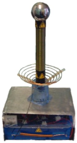
 This Tesla coil runs from a 220V mains input at around 1kW to give an awesome display of arcs and sparks. It has been made with a large secondary coil so that the topload has sufficient elevation for some of the experiments it will be used for and so that it can be upgraded to higher power levels in the future.
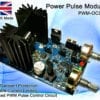
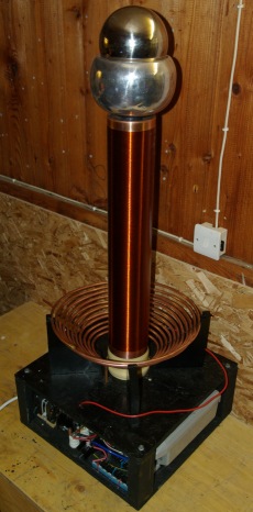

 The supports for the coils were made on a piece of wood which was dried and sealed before use. Even very dry wood can attract high voltage discharge to it, so it is important that it is kept very dry and sealed to prevent it from absorbing more moisture. Plastic is much better to use but can be expensive and harder to work with.
 Based on the NST used in this coil the arcs theoretical limit is 136cm. The actual length we have got so far is
 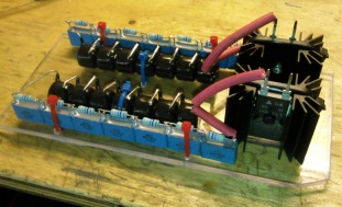 High Voltage Filter
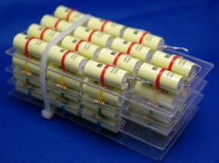
 With smaller
 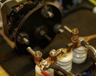 The spark gap used here is a synchronous rotary spark gap. This means that a motor spins around, moving some connected electrodes past the two main electrodes so that it will make a connection as it passes and break it again as it moves away. The spark still needs to jump but it is just about 1 or 2mm. The motor turns around exactly 25 times per second and is in phase with the 50Hz mains current. The four electrodes fixed on the rotating wheel are electrically connected and will connect the capacitor to the primary coil 100 times per second. The position of the rotating electrodes must match perfectly with the mains frequency so that the connection occurs when the capacitor is fully charged (at the peak of each positive or negative half cycle). An external control was made for controlling the phase of the motor so that it can be matched for optimum performance when it is running.
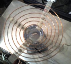
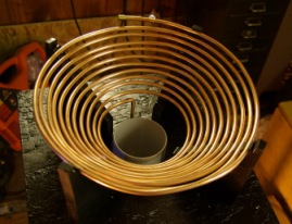 The coil is made from standard 6mm copper plumbing pipe. This is quite soft so it is easy to wind into a coil shape.
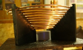 The coil was wound in a conical shape to allow for a good coupling to the secondary coil. If the power is upgraded in future it would be necessary to add a grounded strike rail above this to protect it from being hit by the Tesla coils output. It may even be necessary to replace the coil with one of a flatter design.
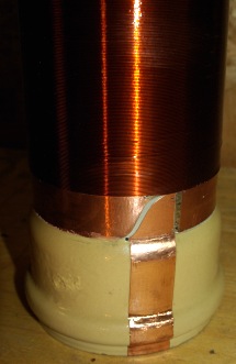
 The secondary coil was wound on a piece of standard 11cm diameter waste pipe. This piece had a push fit type connection at one end which would be used to mount the coil on the Tesla coils base.
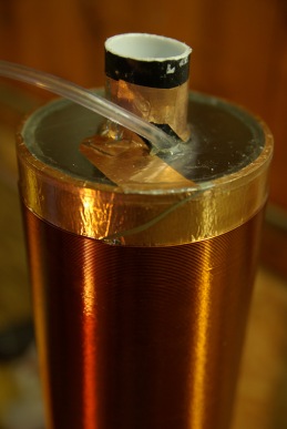
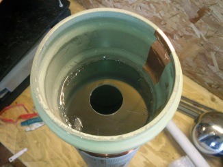
 Because this is an RMCybernetics Tesla Coil, we like to do it a little differently. Down the center of the secondary coil is a piece of 32mm drainage pipe. it is held in place by plastic discs which are epoxied in place. Around this central pipe is another pipe that is wound as a coil along its length. This pipe is about 20m long when uncoiled.
 The topload is made using two separate spheres. The larger one is an upturned
  The size of the topload will have an effect on the resonant frequency of the Tesla Coil. With the topload as shown the secondary coil had a resonant frequency of around
  Control Box
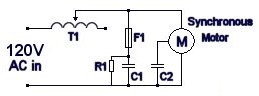 This diagram shows how the motor is wired to a variac for electronic phase control. This really makes things a lot easier to get the coil running well. A small variac (T1) passes power to the synchronous motor. The inductance of the variac combined with the capacitance C1 will allow small adjustments in phase of the synchronous motor. It is necessary to turn the variac to maximum to start the motor and allow it to lock on to mains frequency. It can then be turned back about 1/4 of a turn to adjust phase by about 25 degrees before the motor looses lock.
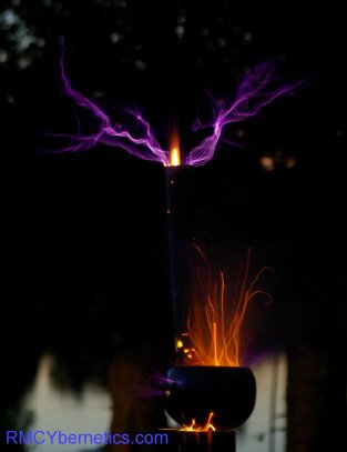 To launch the rocket, a remote trigger for igniting the fuse was needed. This was made by using a home made air operated switch that connects a 12V battery to a 10 ohm resistor. The resistor heats up quickly and ignites the rockets fuse. The battery, switch, and resistor must all be contained within the topload sphere as they will be protected from the high frequency, high voltage. The airline passes down the inside of the secondary and out to a large syringe near the control box. When the syringe is pressed, the switch activates and the rocket launches.
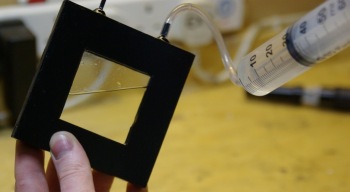
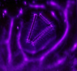
 A kirlian photo is a photograph of electrical corona produced around objects under the influence of high voltages.
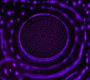
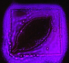
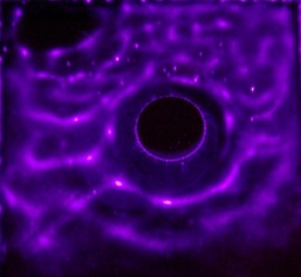
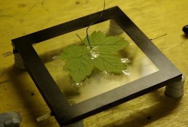
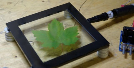
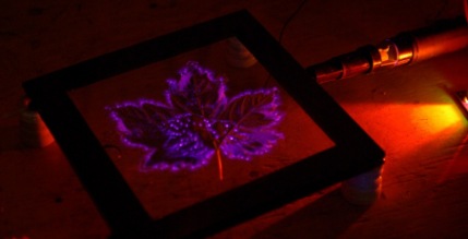
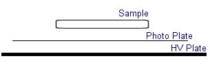
 If you don’t have photographic paper you could use the film from a polaroid camera. Polaroid cameras will eject a protective layer of card when you first insert a film. You can use this feature to develop your exposed film.
 Many people claim that this sort of photo is showing the “life force” or “aura” of living things. This is something many pseudoscientists are using as so they can sell you these sorts of cameras for thousands of dollars. This page should hopefully show you how simple they actually are and that it is just simple corona and ionisation effects that are being observed.


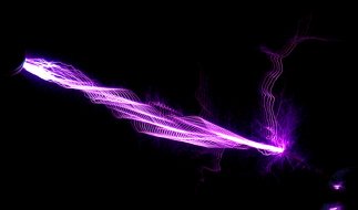
 Using Butane gas and air, a blue flame can be used as an interesting discharge terminal. The heated CO2emissions provide a low pressure channel to conduct the electricity more easily than air. This produces a large plasma column above the flame. At certain spark gap discharge rates the plasma column can be made to resemble a stable double helix formation. Small quantities of other gasses such as neon or helium can be mixed with the butane to produce slightly different colours and effects. The table below should help you find some of the components needed for this project.
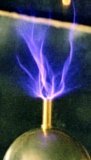
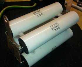
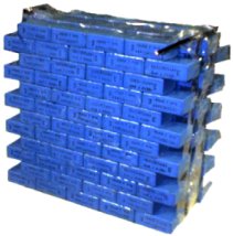 Capacitor Bank – The capacitor used in this project was made by combining a large number of lower valued capacitors. By connecting smaller capacitors in series the overall voltage they will tolerate is increased. To obtain a higher storage capacity (capacitance) the capacitors can be connected in parallel. This type of capacitor bank is known as an MMC (Multi Mini Capacitors). The next version of this project will use specially designed large pulse discharge capacitors. These capacitors can be more efficient than an MMC, but they can be expensive and hard to find.
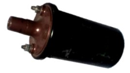 Primary Transformer – Ignition coils (Induction coils) obtained from a scrap yard are used for this design. The old ignition coils provide a very cheap way of generating a high voltage for charging the capacitor. The voltage increase in an ignition coil is not determined by the turns ratio like in normal transformers. The secondary voltage depends upon the rate of change of the current in the primary coil. Older ignition coils such as ones from a scrap yard may not work as well as new ones. Over time the insulating oil inside the casing becomes less effective and can lead to internal arcing. This can damage the transistors and the control circuit, rendering them useless
 Control Circuit – The
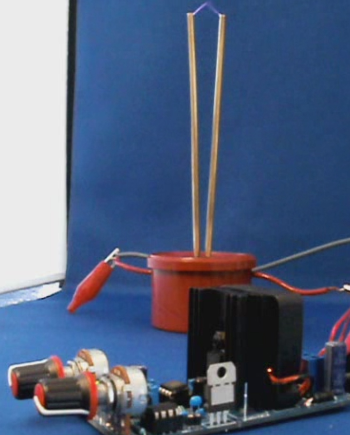
 Coils – The primary coil is simply made from 2mm enameled copper wire, wound around a plastic stand. There are six turns in total, but the connection is made at about 4.5 turns when tuned. The secondary coil is wound from 0.4mm enameled copper wire around a plastic drainage pipe.
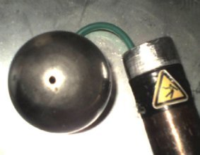 Special Features – This project has several extra features compared to a common Tesla Coil. The topload sphere has a small hole to allow gas to be emitted. A 5mm plastic pipe runs down the inside of the secondary coil, and out of the plastic base.
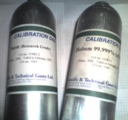 Future Developments – This project is currently being upgraded. The new design aims to achieve a higher power throughput. By using more ignition coils in parallel it should be possible to increase the size of the spark gap, or to fire it more rapidly. New ignition coils will used instead of the second hand ones for improved stability. The new design also incorporates voltage and power monitoring features. It also has a neat metal finish and multiple outputs so that it can be used as a multi purpose portable high voltage power supply
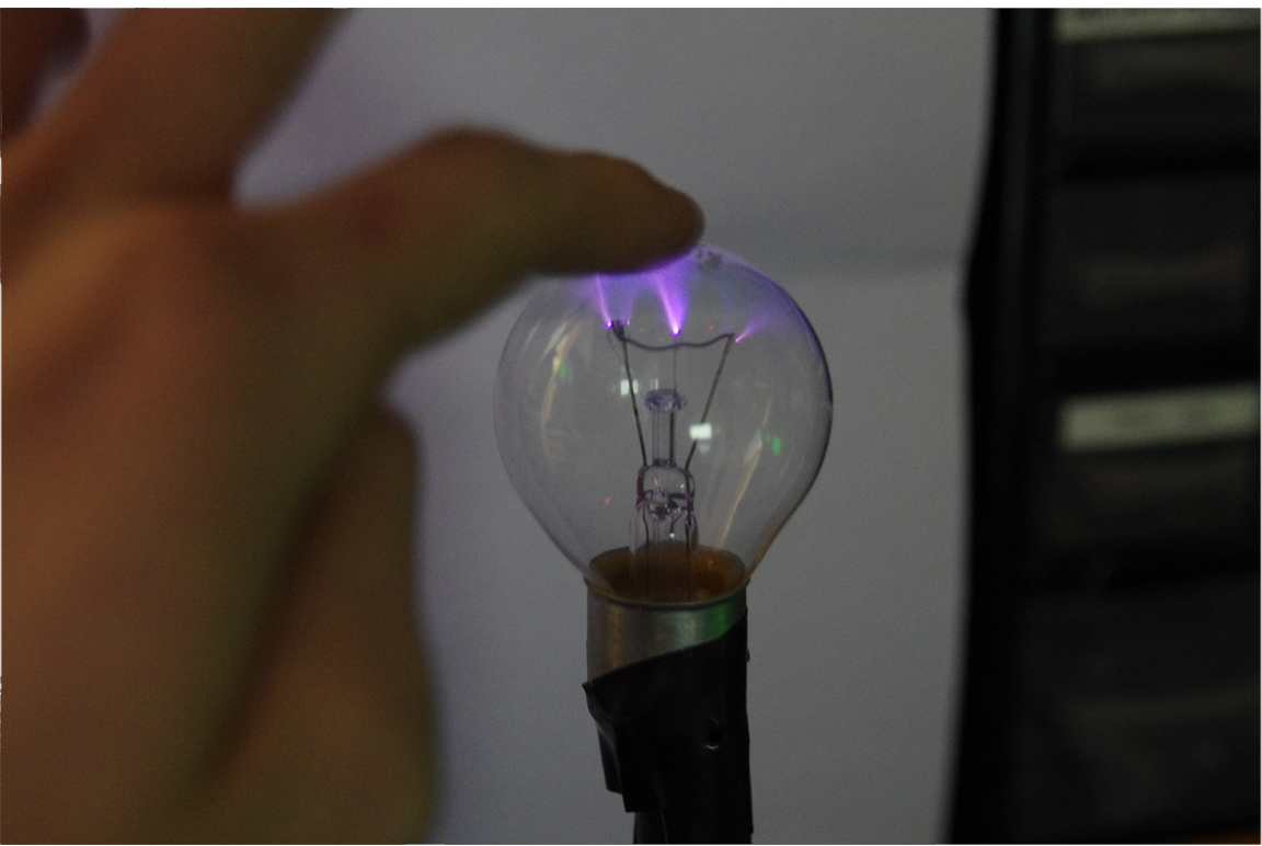
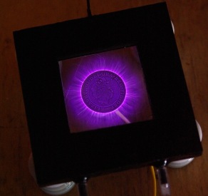
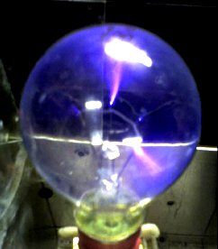 There are all sorts of ways to make a plasma globe. This page deals will detail how to make one using a small amount of easily obtainable components. A normal transparent light bulb can be used as a plasma globe simply by connecting it to a high voltage, high frequency source. Most light bulbs contain low pressure Argon gas to prevent the hot filaments from burning. Fortunately this arrangement is also ideal for making contained arcs of plasma. The power supply required for the plasma globe would preferably be a high voltage, high frequency AC type, which could be made from an

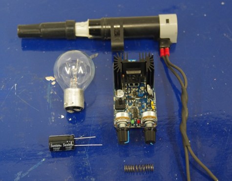 The following parts are used for the video demo of this project;
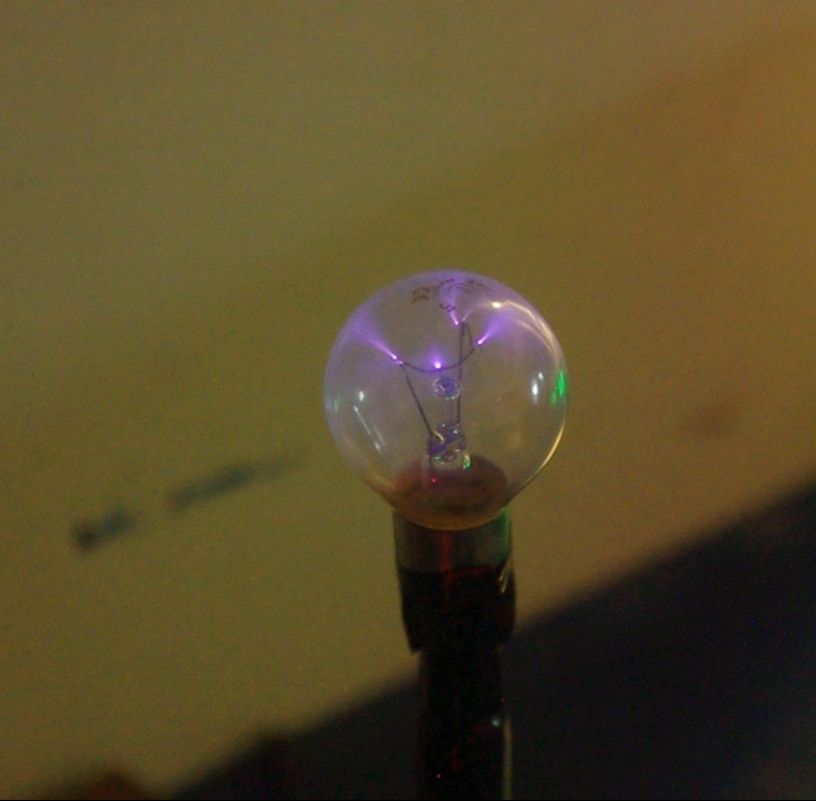
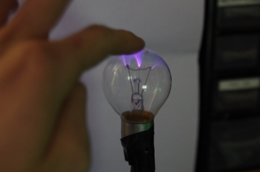 The settings on the PWM circuit will need to be adjusted so that good streamers become visable in the coil. Always begin with the duty setting at zero then slowly turn it up to around 50%. The frequency setting is then adjusted while observing the apperance of the plasma inside the lightbulb. At some frequencies no plasma will be seen, while when at the right frequency there should be lots of streamers dancing around inside the bulb. The frequency needs to be fairly high and the buzzing sound from the coil will become so high its is amost inaudiable.
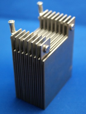
 How it works
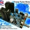


 The electrodes are typically made from metal or graphite (carbon) so that they can pass electricity into the water. It is important that the chosen material does not react readily with oxygen or one of the dissolved compounds otherwise reactions will occur at the surface of the cathode (negative electrode) and the water will become polluted with the products of the reactions. You will see an example of this below when copper electrodes are used. This also means that no or very little oxygen gas is released as it gets combined with the metal electrode and remains in the container.
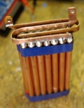 The Project
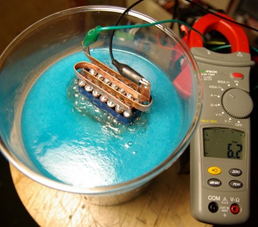
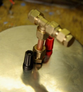
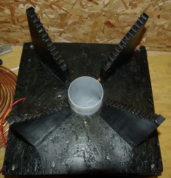
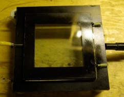
 The container was made from metal so it was important to place the electrodes on a plastic base to prevent any short circuits. This image shows how two banana sockets were installed either side of some copper and brass fittings used to extract the gas. The power and pipe fittings were screwed tightly and sealed with silicon sealant so that the closed container would be air tight.