RMCybernetics offers a range of excellent scientific services. We work with organisations and individuals all over the world on projects involving scientific and technical consultancy, custom electronics, cybernetics and physics research, media production for magazines, television and online.
We also provide wide selection of free science information and support via our website. If you are interested in any of the services mentioned above, please contact us, otherwise, take a look at the links below for a selection of fascinating scientific topics.
A Tiny Homemade Square Wave Signal Generator (‘Dead Bug’ Style)
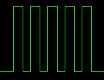
This page shows you how to make a super simple square wave signal generator. The circuit below uses a 555 timer chip, a capacitor, and some resistors to generate a variable frequency, variable pulse width square wave. The term ‘dead bug’ refers to the way that the finished circuit resembles a dead insect. This is because the solder connections are made directly to the components and there are legs sticking out making it look much more messy than the diagram below.
This is a very basic circuit and therefore does not produce an ideal square wave over the full frequency range. The pulse width or duty cycle can only be varied by a small amount, and doing so also effects the frequency output.
This diagram shows how the circuit can be wired without the need for any circuit board. A 14 pin IC socket is used to hold the main circuit so the 555 chip and the two pots can be simply plugged in. The total parts list is shown below.
If you want to switch loads like coils, motors and lights, our range of Cyber Circuitsare for you!
The diagram represents a view from below and is not to scale. The circuit may be a little tricky to solder, but its about as simple as you can get for a signal generator.
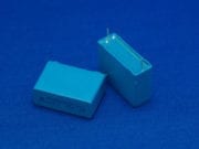
The value of the capacitor C1 will determine the range of frequencies produced. Somewhere around 0.1 to 0.01 microfarads should be adequate for mid range audio frequencies.
A DIY Square Wave Signal Generator with Pulse Width Modulation
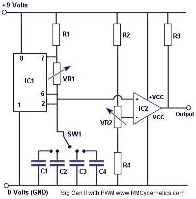
This circuit is very simple and has a fantastic range of potential uses. The two potentiometers (variable resistors) allow the frequency and pulse width to be varied independently and without affecting each other like in the super simple signal generator.
By incorporating a rotary switch, the value of the timing capacitor (C1) can be adjusted. This allows the frequency to be adjusted over the full range that the 555 timer can support.
A separate chip (LM393) is used to control the pulse width so that it will not effect the frequency. The LM393 is a ‘Low Power Low Offset Voltage Dual Comparator’ The pot (VR2) is used as part of a voltage divider so that the voltage on the inverting input of the comparator can be smoothly varied. This voltage determines the pulse width of the final output signal.
Since the pulse width is relative to the input voltage on the this input, it is possible to use the circuit in conjunction with a multitude of robotic interface boards. This signal can be used to drive a H-Bridge or power transistor which is ideal for varying the speed of a DC motor. We have some circuits based on this idea on the Cyber Circuits page. We also have a simple DIY version of this device here
Potential Uses Might Include:
DC Motor Speed Control Control
Boosting or Variable Dimming for LED’s and Light Bulbs
Transformer or Ignition Coil Driver
This circuit was used in the Power Pulse Generator project as part of the Ignition Coil Driver
How to Make a Van De Graff Generator
(An Electrostatic Generator)
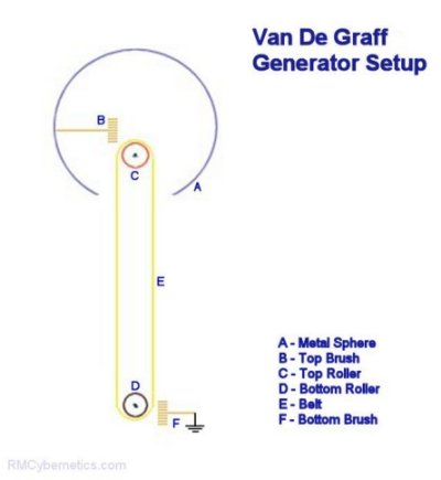
There are a number of devices that utilise contact electrification. A popular device is the Van De Graff Generator as it is very simple to construct. This device will produce very high voltage electricity at very low current. This means that they can be safe to touch, although it may make your hair stand on end!
It works by using two rollers and a belt made from dissimilar materials. As the belt rotates, charge separation will continually occur at the point where the belt moves away from each roller. If a metal brush is placed near to these points then the charge can be collected or deposited. The choice of belt and roller materials will determine the polarity of the voltage produced.
A very simple mini Van De Graff Generator can be made from household parts. It wont make your hair stand on end, but it could produce as much as 20,000 Volts. The following parts (or equivalent) can be used for this project.
Large rubber band
Large glass fuse
Small metal rod, or a nail
Plastic pipe (~4cm diameter)
Insulation tape
Small motor & batteries
Empty drinks can Wire
First of all a piece of PVC pipe or an equivalent insulating support is cut to size. To this the rollers are attached at each end. The top roller should just spin freely on its axle. The bottom roller should be parallel to the top one and raised up from the base of the support so that is can spin freely and be driven by a motor.
The belt should not be too tight that it creates excess friction as this would be noisy and inefficient. It is common to create a belt driven pulley to link the motor to your bottom roller as this provides a speed reduction and torque increase from the motor. A motor speed controller would also help so that the speed can be adjusted for optimum results.
The wire brushes should be place near to but not touching the roller or belt. It is likely that you will need to experimentally determine the optimum position of the brushes.
The top sphere acts like a capacitor to store energy in the form of displaced charges. Ideally is should be large, round and smooth. Any sharp protrusions on the outside of the sphere will cause corona leakage and prevent a good build up of charge. A single drinks can will work on a small scale and they can even be stacked together for better results.
The circuit is great for controlling the power delivered to a device such as a fan, LED’s or even transformers and coils. By adjusting the pulse width you can easily control the speed of a fan without sacrificing torque.
The transistor used is not critical but generally something with voltage and current ratings suited to your application should be used. We have a range of MOSFETs and IGBTs available. The circuit will run from a 6V – 12V DC supply and the output can be made as ‘open collector’ for higher voltage switching.
Don’t fancy building this DIY PWM Circuit yourself? Check out our range of advanced pulse generators
This circuit diagram shows the load (coil, motor etc) connected to the same supply as the rest of the circuit for simplicity. If you need to switch a higher voltage, the +ve connector of the load can simply be connected to an external supply.
If the circuit is to be used with inductive loads a small capacitor should be connected across the load These are often already fitted on small DC motors. An additional component such as a varistor or ‘freewheel diode’ is also recommended if the pulse generator is driving high voltage flyback transformers like ignition coils.
The two potentiometers VR1 and VR2 are used for controlling the frequency and duty cycle of the output. VR1 adjusts the rate at which C1 is charged for modifying frequency, while VR2 acts as a potential divider allowing a specific voltage to be put on the inverting input of IC2. This voltage is used to control the pulse width of the output. The output duty cycle or pulse width of the device can also be controlled by an external voltage such as a microcontrollers or analog signal. The analog voltage source can simply be connected to the inverting input instead of the output from VR2.
Open collector output allows for use of separate voltage source for pulses.
Independent frequency and pulse width / duty cycle controls
Frequency adjustable between 0Hz and 125kHz (C1 must be changed for full range)
Pulse width fully adjustable between 0% and 100%
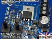
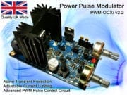
We have a few of these pulse generators designed for use with high voltage transformers which available on the cyber circuits page. These are high quality, ready made on a PCB including a large heatsink and fan, overload protection, and back e.m.f. inductive protection. Theses devices are quite resilient and are ideal for hobbyists and experimenting due to the wide range of potential uses and durability for handling varied loads. If you have random transformers or are making your own coils, these power pulse modulators are ideal for testing and driving them.
Don’t fancy building it yourself? Check out our advanced pulse control circuits. Buy our awesome PWM-OCXI now!
Using a voltage multiplier is a great way to make a high voltage DC power supply. It is very easy to generate high voltages from easily available components.
This page contains information on where to buy the components and how to connect them. It also gives details of sources of mini high voltage power supplys (inverters) which will run from batteries.
WARNING: Very High Voltage Device!
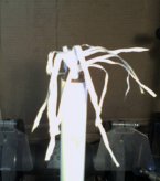
You can see what high voltage static electricity from this device does to a piece of one way window film in the violent discharge experiments section. There are microscope images of the aftermath and a video clip of the explosive action!
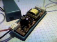
For efficiency a voltage multiplier should be powered from a source that is already a relatively high voltage. There are a variety of small battery operated high voltage power supplys available. Many lighting devices contain inverters for powering vacuum tubes such as, florescent lights, cold cathode lights and plasma globes. These types of devices usually run from 12V DC and can output voltages up to around 20kV AC.
Mini cold cathode tube PSU – ~1kV
Plasma Globe PSU – ~15kV
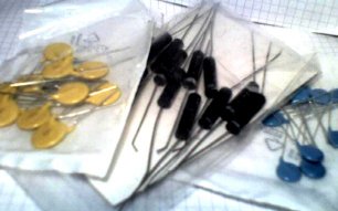
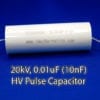
The capacitors and diodes required for the multiplier can be purchased from our shop.
The capacitors and diodes can be arranged in a variety of ways. The half wave method is the easiest as it requires fewer components, but a full wave circuit will perform better. If you just want to get one working as soon as possible the the half wave method would be adequate. The circuit diagrams below indicate how the components should be arranged.
The schematics above will output a positive DC voltage relative to the ground (GND). If a negative output is required then the polarity of the diodes should be reversed. you can learn more about how a voltage multiplier works, by visiting the voltage multiplier page.
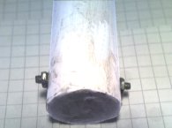
For safety and improved performance the voltage multiplier should be placed in a protective casing, such as a PVC pipe filled with oil. The image on the left shows two protruding screws used for the AC input connection, and he other image shows polished coin used for the high voltage output. By using Polymorph to seal the ends of the pipe, it can be filled with oil to prevent corona leakage from the internal connections. A more sturdy method would be to fill the pipe with epoxy resin, but this may be difficult with compact component arrangement.
Example Experiments Ahomemade voltage multiplier is perfect for powering an EHD thruster (aka Lifter). An EHDT can be made from just aluminium foil, sticks, and fine wire. To learn how , see the ElectroHydroDynamic Thruster page.
Using freezer spray (used by plumbers) you can grow ice crystals on the HV output with interesting results.
For more Simple Experiments with static electricity see the Experiments Section
A DIY Homemade Ignition Coil Driver Circuit – A High Voltage Power Supply
One of the simplest ways to make a battery powered High Voltage power supply is to use a common car ignition coil. Ignition coils are a type of induction transformer based on the Tesla Coil invented by Nikola Tesla in 1891. The voltage rise is not given by the turns ratio like in a standard transformer, but is proportional to the rate of change of current in the primary circuit. This means to get a high output voltage you must be able to stop the power flowing into the coil as quickly as possible. In old cars this was simply done mechanically. For use as a HV power supply this needs to happen rapidly over and over. To do this a spacial square wave power supply is uses which switches power on and off to the coil hundreds or thousands of times per second.
WARNING: High Voltage is generated by this device!
Standard ignition coils can be obtained from most car parts stores for around £25. It is not essential to use two 12V batteries like shown in the circuits shown below, but it will allow you to obtain bigger sparks. We have some compact induction coils available for sale for under £20. Click the link to check stock.
This driver circuit is based on the commonly used 2n3055 transistor due to it high power switching capability. While these are cheap and high temperature tolerant, they are susceptible to voltage spikes caused by the inductive nature of the load (ignition coil). Pretty much any power transistor, IGBT or MOSFET can be used in this circuit as long as it is rated for at last 5A and 100V. Ones with higher voltage ratings will be less likely to be damaged by spikes. Further protection methods are outlined lower down this page and in the comments. If you use a MOSFET or IGBT instead of a bipolar transistor like the 2n3055, you should also add a pulldown resistor of about 10k between the base/gate pin and GND.
RC1 is used to help suppress high voltage spikes that can destroy the power transistors.
T2 represents two power transistors connected in parallel and mounted on a heatsink.
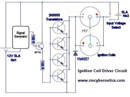
This next circuit is designed for a higher powered output. Two ignition Coils are connected in parallel but with opposite polarity. This means that the output voltages of each coil are out of phase or opposite to each other (when one is positive, the other is negative). Using this configuration the output is taken from the two coils output terminals, whereas the circuit above uses the output terminal and ground.
These circuits will work great for driving ignition coils for high voltage but they can be susceptible to damage from inductive spikes. When an ignition coil is being driven unloaded (open circuit on the output) there will be significantly increased back emf and risk of damaging the driver circuit. We sell an ignition coil driver module which has built in protection against most spikes that would damage a driver. It also includes an early warning indicator which will show you how severe the back emf is from your load.
Protecting Your Ignition Coil Driver
If you build an ignition coil driver to make high voltage sparks and arcs, you will need some sort of EMI protection for your circuit. Without it, it is very likely you will destroy the transistors or driver ICs.
Snubbers are a tricky subject, but in general they are used to reduce electromagnetic interference (EMI) or voltage spikes. There are many ways to reduce EMI and it can often be useful to use various snubbers in different parts of the circuit. These diagrams represent a few possible ways you can snub EMI in an ignition coil driver. These are known as dissipative snubbers because the excess energy is disspated as heat or light.
The top digram uses a series connected capacitor and resistor. The values used will depend on your drive frequency. (See RC1 at top of this page). Generally speaking, a bigger capacitance and smaller resistance will snub more, but also absorb more drive power thefore reducing efficiency. A compromise must be found that best suits your setup.
The next diagram uses a device known as a MOV (Metal Oxide Varistor). These are semiconductor devices which will only begin conducting when the voltage between its terminals exceeds its rated value. It will stop conducting when the voltage goes low again. In the example shown above, the MOV will short out any spikes coming from the load, but it is also shorting the driver circuits output for the same brief instant. The MOV chosen must be able to dissipate the power ans have a voltage rating that will cause it to activate before the voltage gets too high for the drive circuit.
You can also place a small neon indicator bulb (Ne1)in series with a 1k resistor and place this between the low voltage wires to your ignition coil. This bulb will begin to glow when the back EMF reaches about 100V or more. If you see it glowing, you need a better snubber like RC1 (top diagram) or a MOV (varistor) rated to clamp the voltage below the maximum your components will tolerate.
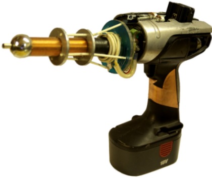
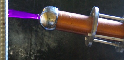
A Hand Held Tesla Coil Battery Powered ‘Plasma Gun’
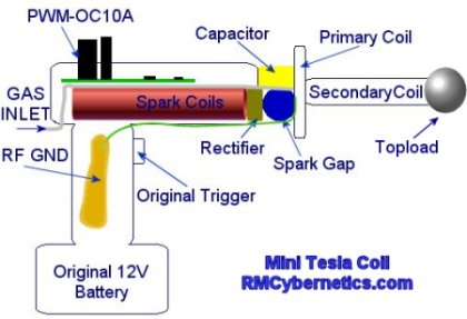
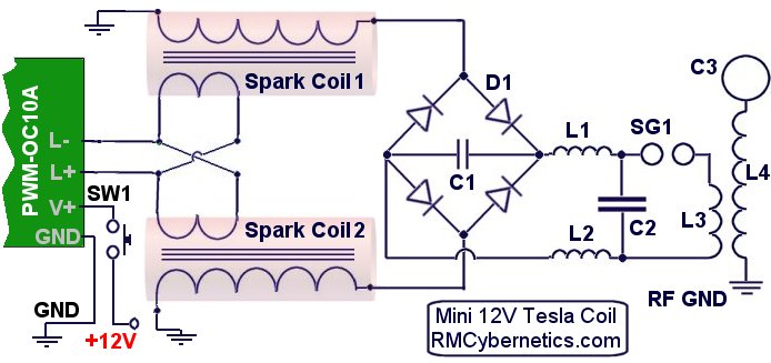
The design for this Tesla Coil is based on the larger battery powered DIY Tesla Coil project but with the aim of getting a much smaller and portable device. A Power Pulse Modulator circuit is used to drive two small high voltage ignition coils wired together in an ‘anti-parralel’ configuration. The output is rectified and used to charge the tank capacitor of a small spark gap Tesla Coil.
WARNING: This project uses dangerous high voltages!
This project is quite old now. Check out the new, more powerful DIY Plasma Gun!
The device is packed into the casing of cheapo cordless drill from a DIY store. This drill used an 18V battery and comes with a charger which made it ideal for the project. The ignition coil driver circuit used takes a direct 12V – 30V input which is connected using the original switch from the drill.
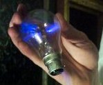
This video clip shows the plasma gun causing a nearby light bulb to light up as if it were a plasma globe.
The high frequency, high voltage from the plasma gun causes the Argon gas in the light bulb to become ionized. This creates streamers that are attracted to the fingers holding it.
The device draws about 6 amps from a well charged 12 V battery which makes the total power consumption to around 72 watts. Unfortunately this low power means the plasma arcs will be limited in size, but since it is hand held that’s probably a good thing. The typical length of the output arcs is between 5 and 7cm
Such a small Tesla Coil inherently has quite a high resonant frequency which in this case is about 500 kHz. This frequency is too high to feel as electric shock but when being zapped you can feel the low frequency component of the spark gap firing rate.
The main driving circuit is a type of pulse width modulation circuit with protection against high voltage spikes. It is adjusted to get the maximum output from the two ignition coils.
The two ignition coils were stripped of the casing in order to reduce the overall size and allow access to the internal wiring. The inputs are wired in an anti-parallel arrangement to help keep the charging voltage high when under load.
The HV outputs of the spark coils are connected to a rectifier (D1) made from four HV diodes potted in epoxy resin. Connected to this is a small smoothing capacitor (C1) which helps to reduce the ripple in the HV DC output. The tank capacitor (C2) is charged from the HV DC supply via two RF chokes (inductors L1 & L2) which serve to prevent the RF oscillations of the TC primary circuit from interfering with the rest of the circuit.
The previous battery powered tesla coil design needed to be well connected to a good RF ground such as a metal rod in the earth. Without this the output would be limited and the driver circuit would be prone to failure.
With this mini tesla coil the RF ground connection is made by connecting it to a copper pad on the handle.
The body of the person holding the device is used as the RF ground and the large area of copper ensures the energy is spread out to prevent RF burns.
In most Tesla Coils this would not be safe at all but this device is very low power so there is little risk of electric shock. The RF its self probably isn’t too healthy though!
The TC part (Tesla Coil) uses the common single static spark gap and flat primary design for simplicity and size. The primary coil is closely wound around the base of the secondary with several layers of insulation tape preventing flashover.
The topload sphere is made from a metal draw handle which has been drilled to allow gas to be ejected from the end. A pipe from this sphere runs down the inside of the secondary and to the back of the handle where it can be connected to a gas supply.
Using noble gasses such as Argon or Neon will cause the output arcs to be forced along the flow of gas. This allows the plasma to be directed in a straight line from the tip of the plasma gun. It is also possible to use butane gas which makes this thing into some kind of flamethrower – plasma gun hybrid. The electricity is conducted along the flame from its tip. You can see photos of this effect on our plasma page.
Apart from making cool arcs of plasma, this device even transmits wireless electrical power. It can light bulbs and fluorescent lights just from being nearby.
The interference created by this wireless energy can cause all sorts of electronic devices to switch on and off or start behaving erratically. This is because the energy is causing tiny currents to be induced in the tracks and wires in the devices. If a simple circuit had a matching resonant frequency to that of the plasma gun, it would be possible to collect the wireless energy from a greater distance.
There are several improvements that could be made on this design which could result in a greater power throughput and therefore bigger arcs.
The spark gap is just a single gap which has been seal inside a plastic case for safety and size. This sort of switching will have poor performance due to quenching difficulties and oxide buildup. A solid state version would be better but it would likely be larger and considerably more expensive. A larger topload would allow for larger breakouts, but it would also need more primary capacitance. The secondary coil is also rather long relative to its width. Ideally this would be shorter and wider.
In conclusion this was a fun project and we hope you find this information useful and interesting.
A Multi-purpose power pulse generator capable of driving Tesla Coils and other high power coils. This device is based on the Homemade Tesla Coil project and uses an improved version of the ignition coil driver circuit to generate high voltages.
This unit quite simply can generate high current pulses of variable frequency and pulse width. This unit uses the Square wave frequency generator shown in the DIY Devices section for the main signal source but any other signal source can also be connected to it. The input signal is amplified using an array of nine 2N3055 power transistors (T2) which is capable of switching huge amounts of power.
WARNING: High Voltage is used in this project!
A switch allows power to be sent to external coils for low voltage applications, or the internal ignition coils can be powered for charging a large HV pulse discharge capacitor.
The low voltage circuit in this device is similar to the driver for the Homemade Tesla Coil, but with some important differences. The high current pulses from the Lead Acid Batteries makes the signal generator unstable in the original design. The new version uses a completely independent signal source with its own battery to minimize the interference. There is also an extra buffer circuit to protect the 2N3055 Transistors from voltage spikes caused by the inductive kickback from the auto ignition coils.
All the power electronics are housed in an Aluminum case finished with panel meters, IO ports, and switches. The signal generator circuit is housed in an independent unit with its own 9V battery. This can be connected to the main unit via a shielded cable allowing it to be operated from a safe distance.
The high voltage output from the ignition coils is rectified using some large high voltage diodes (D2) designed for X-Ray machines. The rectified output is connected to a large capacitor (C1) for smoothing the DC output. From the smoothing capacitor an inductor (L1) and an additional ‘de-Q-ing’ diode (D3) have been added to the charging circuit to block the AC ringing from the TC primary coil from reaching the the smoothing capacitor. These also help to protect the the rectifier from short circuits, arcing currents and possible back EMF or transients.
The connectors used here are just standard banana types. They are not designed for high voltage use and will therefore leak a little energy by ionising the air nearby.
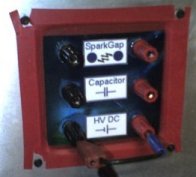
The main high voltage front panel on the box has sockets for HV DC output, an internal HV pulse discharge capacitor, and an internal spark gap. This allows the high voltage circuits to be configured in a number of different ways without having to re-wire any internal components.
The image on the right shows how the panel is wired to drive a Tesla Coil. The spark gap can be adjusted using a handle on the side of the case. Depending upon the resonant frequency of the TC being driven, it may be necessary to adjust the capacitance. This can simply be done by adding more capacitors in parallel, or using a separate one.
This image shows the interconnected outputs of the ignition coils. The ignition coils are wired in parallel to give a higher output current.
All the high voltage cabling inside the box is placed inside flexible plastic tubing for added insulation. You can see here that the low voltage connections to the ignition coils are also covered with tubing for added protection.
The case is grounded by connecting a thick wire to a long metal spike driven into the ground. All of the ground connections for the internal circuits are also connected to the case.
Connecting the case to the earth spike is essential when using the device to drive Tesla coils. This is because a Tesla Coil (TC) will generate radio frequency (RF) currents that would otherwise become present throughout the circuit. Without a good RF ground you would probably receive little shocks from the controls when operating a Tesla Coil.
Internal Variable Spark Gap
This new spark gap is made using three spherical electrodes in a high K dielectric casing. The double casing of the spark gap reduces the overall noise and allows the airflow to be doped with other gasses.The anode and cathode are spaced further than the voltage could jump and the third sphere can be moved in and out of the gap via a long glass fibre rod. This allows the spark gap to be adjusted smoothly anywhere between short and open circuit whilst it is active.
A pair of 12V DC brushless fans are installed to improve airflow through the spark gap. This is not to improve quenching, but it will reduce electrode corrosion from Ozone buildup in the spark gap casing. A further filtering capacitor has been added across the fans connectors as this type is sensitive to voltage spikes
Controls
The control circuit used for generating the driving signal is made using a 555 based circuit. This circuit can be found on the DIY Devices Page and is titled Signal Generator with Pulse Width Control. This circuit is housed inside a small hand held box with a 9V battery. It can be connected to the Power Pulse Generator by a jack plug on the end of the cable from the unit. You can buy an advanced version of this signal source here.
Different ignition coils or transformers will have different resonant frequencies. Using this circuit allows the Ignition coils to be tuned and driven at their resonant frequency.
External transformers, coils, or solenoids can also be driven at any desired frequency within the range of the 555 timer. The pulse width modulation capabilities of the control circuit are used for power level control for transformers and other coils. This feature also allows large or small DC motors to be powered with variable speed between 0% and 100%. These can also be tuned to their resonant frequency.
This device is capable of powering a multitude of experiments and is great for any researcher experimenting with pulsed power or resonant applications. You can see experiments we have done with Tesla Coils using this device on the Tesla Coil Experiments page.
 This page shows you how to make a super simple square wave signal generator. The circuit below uses a 555 timer chip, a capacitor, and some resistors to generate a variable frequency, variable pulse width square wave. The term ‘dead bug’ refers to the way that the finished circuit resembles a dead insect. This is because the solder connections are made directly to the components and there are legs sticking out making it look much more messy than the diagram below.
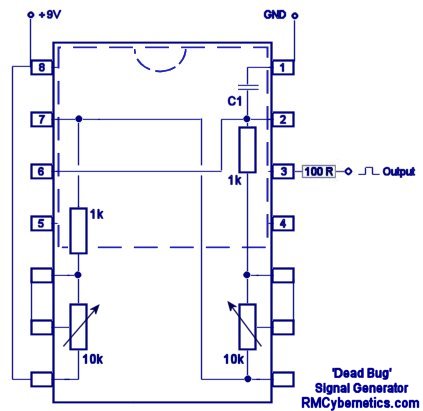
 A very simple mini Van De Graff Generator can be made from household parts. It wont make your hair stand on end, but it could produce as much as 20,000 Volts. The following parts (or equivalent) can be used for this project.
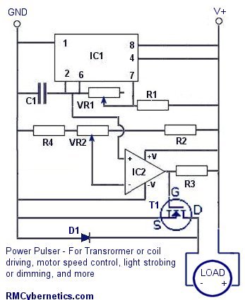

 Using a voltage multiplier is a great way to make a high voltage DC power supply. It is very easy to generate high voltages from easily available components.
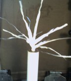 You can see what high voltage static electricity from this device does to a piece of one way window film in the
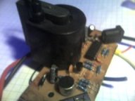
 The capacitors and diodes required for the multiplier can be purchased from our
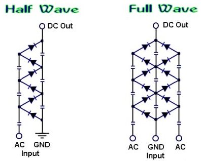
 The schematics above will output a positive DC voltage relative to the ground (GND). If a negative output is required then the polarity of the diodes should be reversed. you can learn more about how a voltage multiplier works, by visiting the
 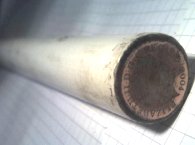 Example Experiments
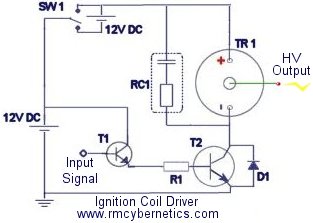
 This next circuit is designed for a higher powered output. Two ignition Coils are connected in parallel but with opposite polarity. This means that the output voltages of each coil are out of phase or opposite to each other (when one is positive, the other is negative). Using this configuration the output is taken from the two coils output terminals, whereas the circuit above uses the output terminal and ground.
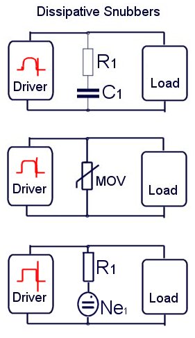 If you build an ignition coil driver to make high voltage sparks and arcs, you will need some sort of EMI protection for your circuit. Without it, it is very likely you will destroy the transistors or driver ICs.

 With this mini tesla coil the RF ground connection is made by connecting it to a copper pad on the handle.
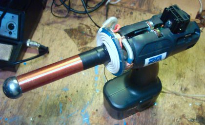
 Apart from making cool arcs of plasma, this device even transmits wireless electrical power. It can light bulbs and fluorescent lights just from being nearby.
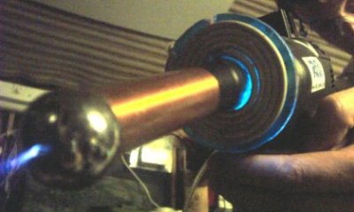 There are several improvements that could be made on this design which could result in a greater power throughput and therefore bigger arcs.
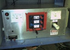 A Multi-purpose power pulse generator capable of driving Tesla Coils and other high power coils. This device is based on the
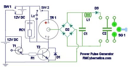
 The main high voltage front panel on the box has sockets for HV DC output, an internal HV pulse discharge capacitor, and an internal spark gap. This allows the high voltage circuits to be configured in a number of different ways without having to re-wire any internal components.
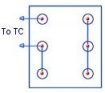 The image on the right shows how the panel is wired to drive a Tesla Coil. The spark gap can be adjusted using a handle on the side of the case. Depending upon the resonant frequency of the TC being driven, it may be necessary to adjust the capacitance. This can simply be done by adding more capacitors in parallel, or using a separate one.
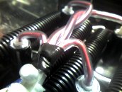 This image shows the interconnected outputs of the ignition coils. The ignition coils are wired in parallel to give a higher output current.
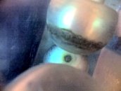 This new spark gap is made using three spherical electrodes in a high K dielectric casing. The double casing of the spark gap reduces the overall noise and allows the airflow to be doped with other gasses.The anode and cathode are spaced further than the voltage could jump and the third sphere can be moved in and out of the gap via a long glass fibre rod. This allows the spark gap to be adjusted smoothly anywhere between short and open circuit whilst it is active.
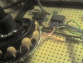 The control circuit used for generating the driving signal is made using a 555 based circuit. This circuit can be found on the DIY Devices Page and is titled