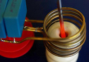
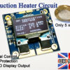
This great little project demonstrates the principles of high frequency magnetic induction and how to make an induction heater. The circuit is very simple to build and only uses a few common components. With the induction coil shown here the circuit draws about 5A from a 15V supply when a screwdriver tip is heated. It takes approximately 30 second for the tip of the screwdriver to become red hot!
The control circuit uses a method known as ZVS (zero voltage switching) to activate the transistors which allows for an efficient transfer of power. In the circuit you see here, the transistors barely get warm due to the ZVS method. Another great thing about this device is that it is a self resonant system and will automatically run at the resonant frequency of the attached coil and capacitor. If you want to save some time, we have an induction heater circuit available in our shop. You might still want to read this article though for some good tips on getting your system working well.
 How Does Induction Heating Work?
When a magnetic field changes near a metal or other conductive object, a flow of current (known as an eddy current) will be induced in the material and will generate heat. The heat generated is proportional to the current squared multiplied by the resistance of the material. The effects of induction are used in transformers for converting voltages in all sorts of appliances. Most transformers have a metallic core and will therefore have eddy currents induced into them when in use. Transformer designers use different techniques to prevent this as the heating is just wasted energy. In this project we will directly make use of this heating effect and try to maximise the heating effect produced by the eddy currents.
If we apply a continuously changing current to a coil of wire, we will have a continuously changing magnetic field within it. At higher frequencies the induction effect is quite strong and will tend to concentrate on the surface of the material being heated due to the skin effect. Typical induction heaters use frequencies from 10kHz to 1MHz.
 DANGER: Very high temperatures can be generated with this device!
 The Circuit
The circuit used is a type of collector resonance Royer oscillator which has the advantages of simplicity and self resonant operation. A very similar circuit is used in common inverter circuits used for powering fluorescent lighting such as LCD backlights. They drive a centre tapped transformer which steps up the voltage to around 800V for powering the lights. In this DIY induction heater circuit the transformer consists of the work coil and the object to be heated.
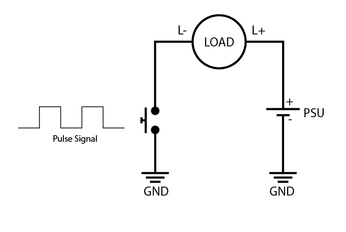
The main disadvantage of this circuit is that a centre tapped coil is needed which can be a little more tricky to wind than a common solenoid. The centre tapped coil is needed so that we can create an AC field from a single DC supply and just two N-type transistors. The centre of the coil is connected to the positive supply and then each end of the coil is alternately connected to ground by the transistors so that the current will flow back and forth in both directions.
The amount of current drawn from the supply will vary with the temperature and size of the object being heated.
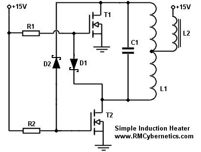 From this schematic of the induction heater you can see how simple it really is. Just a few basic components are all that is needed for creating a working induction heater device.
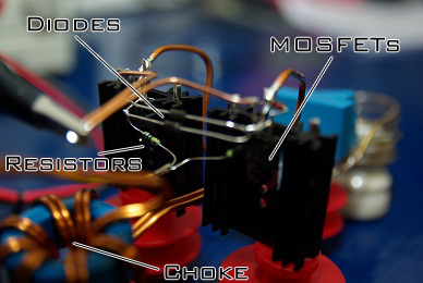
R1 and R2 are standard 240 ohm, 0.6W resistors. The value of these resistors will determine how quickly the MOSFETs can turn on, and should be a reasonably low value. They should not be too small though, as the resistor will be pulled to ground via the diode when the opposite transistor switches on.
The diodes D1 and D2 are used to discharge the MOSFET gates. They should be diodes with a low forward voltage drop so that the gate will be well discharged and the MOSFET fully off when the other is on. Schottky diodes such as the 1N5819 are recommended as they have low voltage drop and high speed. The voltage rating of the diodes must be sufficient to withstand the the voltage rise in the resonant circuit. In this project the voltage rose to as much as 70V.
The transistors T1 and T2 are 100V 35A MOSFETs (STP30NF10). They were mounted on heatsinks for this project, but they barely got warm when running at the power levels shown here. These MOSFETs were chosen due to having a low drain-source resistance and fast response times.
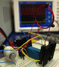 The inductor L2 is used as a choke for keeping the high frequency oscillations out of the power supply, and to limit current to acceptable levels. The value of inductance should be quite large (ours was about 2mH), but also must be made with thick enough wire for carrying all the supply current. If there is no choke used, or it has too little inductance, the circuit might fail to oscillate. The exact inductance value needed will vary with the PSU used and your coil setup. You may need to experiment before you get a good result. The one shown here was made by winding about 8 turns of 2mm thick magnet wire on a toroidal ferrite core. As an alternative you can simply wind wire onto a large bolt but you will need many more turns of wire to get the same inductance as from a toroidal ferrite core. You can see an example of this in the photo on the left. In the bottom left corner you can see a bolt wrapped with many turns of equipment wire. This setup on the breadboard was used at low power for testing. For more power it was necessary to use thicker wiring and to solder everything together.
As there were so few components involved, we soldered all the connections directly and did not use a PCB. This was also useful for making the connections for the high current parts as thick wire could be directly soldered to the transistor terminals. In hindsight it might have been better to connect the induction coil by screwing it directly to the heatsinks on the MOSFETs. This is because the metal body of the transistors is also the collector terminal, and the heatsinks could help keep the coil cooler.
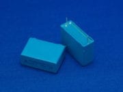
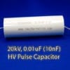
The capacitor C1 and inductor L1 form the resonant tank circuit of the induction heater. These must be able to withstand large currents and temperatures. We used some 330nF polypropylene capacitors. More detail on these components is shown below.
 The Induction Coil and Capacitor
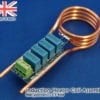
The coil must be made of thick wire or pipe as there will be large currents flowing in it. Copper pipe works well as the high frequency currents will mostly flow on the outer parts anyway. You can also pump cold water through the pipe to keep it cool.
A capacitor must be connected parallel to the work coil to create a resonant tank circuit. The combination of inductance and capacitance will have a specific resonant frequency at which the control circuit will automatically operate. The coil-capacitor combination used here resonated at around 200kHz.
It is important to use good quality capacitors that can withstand large currents and the heat dissipated within them otherwise they would soon fail and destroy your drive circuit. They must also be placed reasonably close to the work coil and using thick wire or pipe. Most of the current will be flowing between the coil and capacitor so this wire must be thickest. The wires linking to the circuit and power supply can be slightly thinner if desired.
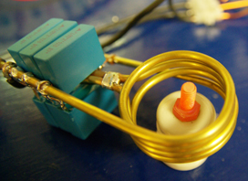
This coil here was made from 2mm diameter brass pipe. It was simple to wind and easy to solder to, but it would soon start to deform due to excess heating. The turns would then touch, shorting out and making it less effective. Since the control circuit stayed relatively cool during use, it seemed that this could be made to work at higher power levels but it would be necessary to use thicker pipe or to water cool it. Next the setup was improved to tolerate a higher power level…
 Pushing it Further
The main limitation of the setup above was that the work coil would get very hot after a short time due to the large currents. In order to have larger currents for a longer time, we made another coil using thicker brass tubing so that water could be pumped through when it was running. The thicker pipe was harder to bend, especially at the centre tapping point. It was necessary to fill the pipe with fine sand before bending it as this prevents it from pinching at the sharp bends. It was then cleared out using compressed air.
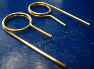 The induction coil was made in two halves as shown here. They were then soldered together and a small piece of pvc pipe was used to connect the central pipes so that water could flow through the whole coil.
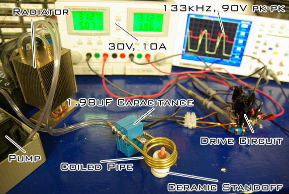
Less turns were used in this coil so that it would have a lower impedance and therefore sustain higher currents. The capacitance was also increased so that the resonant frequency would be lower. A total of six 330nF capacitors were used to give a total capacitance of 1.98uF.
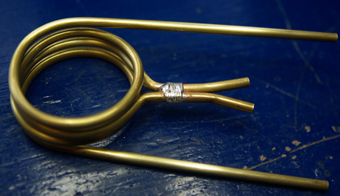 The cables connecting to the coil were just soldered onto the pipe near the ends, just leaving room for fitting some PVC pipe.
It is possible to cool this coil simply by feeding water through directly from the tap but it is better to use a pump and radiator to remove the heat. For this, an old fish tank pump was placed in a box of water and a pipe fitted the outlet nozzle. This pipe fed to a modified computer CPU cooler which used three heat-pipes to move the heat.
The cooler was converted into a radiator by cutting the ends off the heat pipes and then linking them with PCV pipes to the the water would flow through all 3 heatpipes before exiting and going back to the pump.
If you do cut some heatpipes yourself, make sure to do it in a well ventilated area, and not indoors as they contain volatile solvents that can be toxic to breathe. You should also wear protective gloves to prevent skin contact.
 This modified CPU cooler was very effective as a radiator and allowed the water to remain quite cool.
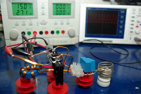
Other modifications needed were to replace the the diodes D1 and D2 with ones rated for higher voltages. We used the common 1N4007 diodes. This was because with the increased current there was a larger voltage rise in the resonant circuit. You can see in the image here that the peak voltage was 90V (yellow scope trace) which is also very close to the 100V rating of the transistors.
The PSU used was set to 30V so it was also necessary to feed the voltage to the transistor gates via a 12V voltage regulator. When no metal was inside the work coil, it would draw about 7A from the supply. When the bolt in the photo was added, this went up to 10A and then gradually dropped again as it heated up beyond curie temperature. It would certainly go over 10A with larger objects, but the PSU used has a 10A limit. You can find a suitable a 24V, 15A PSU in our online shop.
The bolt you can see glowing red hot in the photo took about 30 seconds to reach maximum temperature. The screwdriver in the first image could now be heated red hot in about 5 seconds.
In order to go to higher power than this, it would be necessary to use different capacitors or a larger array of them so that the current was more distributed between them. This is because the large currents flowing and high frequencies used would heat the capacitors significantly. After about 5 minutes of use at this power level the DIY induction heater needed to be switched off so that they could cool down. It would also be necessary to use a different pair of transistors so that they could withstand the larger voltage rises.
In all this project was quite satisfying as it produced a good result from just a simple and inexpensive circuit. As it is, it could be useful for hardening steel, or for soldering small parts. If you decide to make your own induction heater project, please post your photos below. Please read through the other comments before making your own as it could save you time later on.
If you wish to simulate this project for testing different inductance values or transistor choices, please download LTSpice and run this DIY Induction Heater Simulation (Right click, Save as)
How hot will it get?
It is difficult to say how hot you will be able to get something as there are many parameters to consider. Different materials will react differently to induction heating and their shape and size will affect how the heat up or shed heat to the atmosphere.
You can get a rough idea using some basic calculations with the formula below, or if you prefer, we made a handy Heater Power Calculator that can work it out for you. This form includes materials (like water) that can not be directly heating using induction heaters, but it is still useful if you are trying to work out for example the power needed for heating a pan of water using a induction heater.
EXAMPLE: How hot will 20g of Steel get in 30 seconds when heated with a 300W heater? (assuming 100W is lost to the surroundings)
Formulae:
Q = m x Cp x ΔT
ΔT = Q ÷ m ÷ Cp
Working:
(300W – 100W) x 30s = 6000J
6000J ÷ 20g ÷ 0.466J/g°C = 643.78°C
Result:
20g of Steel will increase in temperature by 643.78°C when heated with a 300W heater for 30 second(s).
Troubleshooting
If you have trouble getting this working, here are a few tips to help troubleshoot your home made induction heater project….
PSU (Power Supply)
If your PSU is unable to deliver a large surge of current when the induction heater is powered on, then it will fail to oscillate. The voltage from the supply will drop during that moment (although the PSU may not display this) and this will prevent the transistors from switching correctly. To help with this problem, you can place several large electrolytic capacitors in parallel with the supply. When charged they will be able to deliver a large surge current to your circuit. A good powerful supply would be our 24V 15A DC PSU.
Choke (inductor L2)
This limits the power to your induction heater. If yours is not oscillating, then you may need more inductance to prevent voltage drop in your PSU. You will need to experiment with how much inductance you need. Better to have too much, than too little as this will only limit the power of the heater. Too little may mean it wont work at all. If your inductor core is too small, high current will saturate it and cause too much current to flow and potentially damage your circuit.
Wiring
Keep the connecting wires short to reduce stray inductance and interference. Long wires add unwanted resistance and inductance to the circuit and can result in unwanted oscillations or poor performance. Our 30A power cable is well suited to this.
Components
The transistors chosen must have a low voltage drop / on-state resistance otherwise they will overheat, or even prevent the system from oscillating. IGBTs will proabbaly not work, but most MOSFETs with similar ratings should be OK. The capacitors must have a low ESR (resistance) and ESL (inductance) so they can tolerate the high current and temperatures. The diodes should also have a low forward voltage drop so that the transistors switch off correctly. They should also be fast enough to work at the resonant frequency of your induction heater.
Powering it up
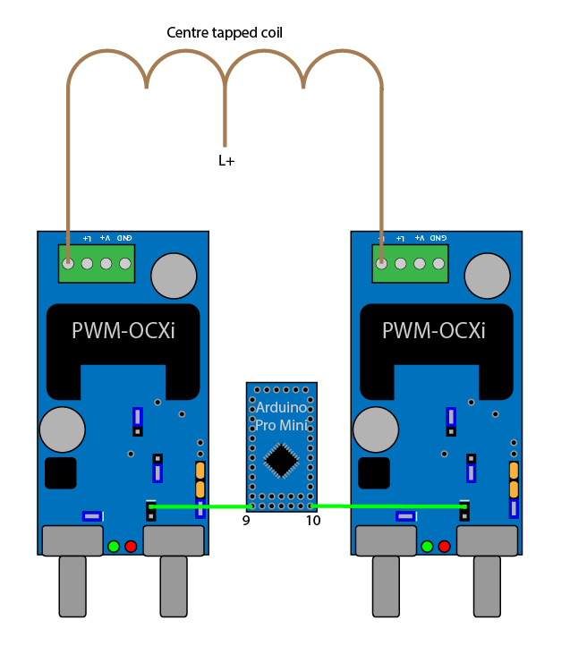
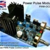
When switching it on, do not have metal within the heating coil. This can lead to larger current surges which could prevent the oscillation from starting as mentioned above. Also do not try to heat large amounts of metal. This project is only suitable for small induction heaters. If you want to control or gradually turn up the power, you can use one of our power pulse modulator circuits. See post 5108 below for details.
Brain
You will need a brain that functions reasonably well to make this project safely. It can be very dangerous to build an induction heater, so if you are new to electronics, you should get someone to help you make it. Approach things logically; If it is not working, check the components used are not faulty, check connections are correct, read this whole article and all the comments, search Google if you do not understand any of the terms, or read through our Learn Electronics section. Remember: Hot things will burn you and can set things on fire; Electricity can electrocute you and also cause fire. Put safety first.
 A DIY Tesla Coil Tuner
 I used two other alligator clips to make a 6 inch jumper to short the spark gap for primary testing.
 Calibration:
 Secondary Fo: To test the secondary’s fundamental frequency, simply connect the TCT between the ground and the base wire from the secondary as shown below. Slowly turn the frequency through the range until the brightest spot is found. The lowest and brightest frequency spot is the fundamental. You may see the dimmer 3rd harmonic at ~3 x Fo. It is probably best to test the secondary frequency on the coil in the actual configuration since the secondary frequency is sensitive to the surrounding objects.
 Primary Fo: To test the primary circuit’s frequency, simply connect the TCT across the primary cap and short the spark gap with the jumper. Slowly turn the frequency through the range until the dimmest spot is found and read the frequency on the dial. You may want to remove the secondary coil to prevent the secondary from affecting this test.
 This part can be quite difficult and time consuming to produce yourself. If you do not want to wind your own, check out our
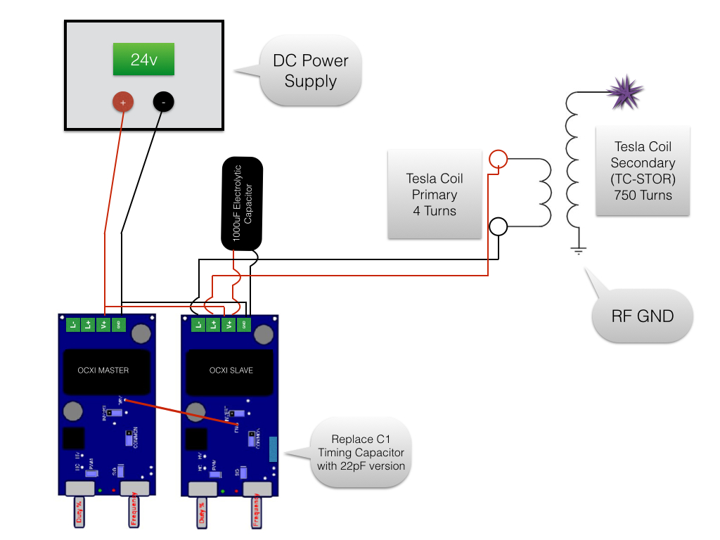
 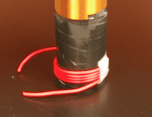 The primary coil simply consists of around four windings of thick copper wire wrapped around the base of the secondary coil. It is best to use something well insulated as it prevents corona leaking energy from the primary coil. In this example we used
  The SSTC Drive Circuit
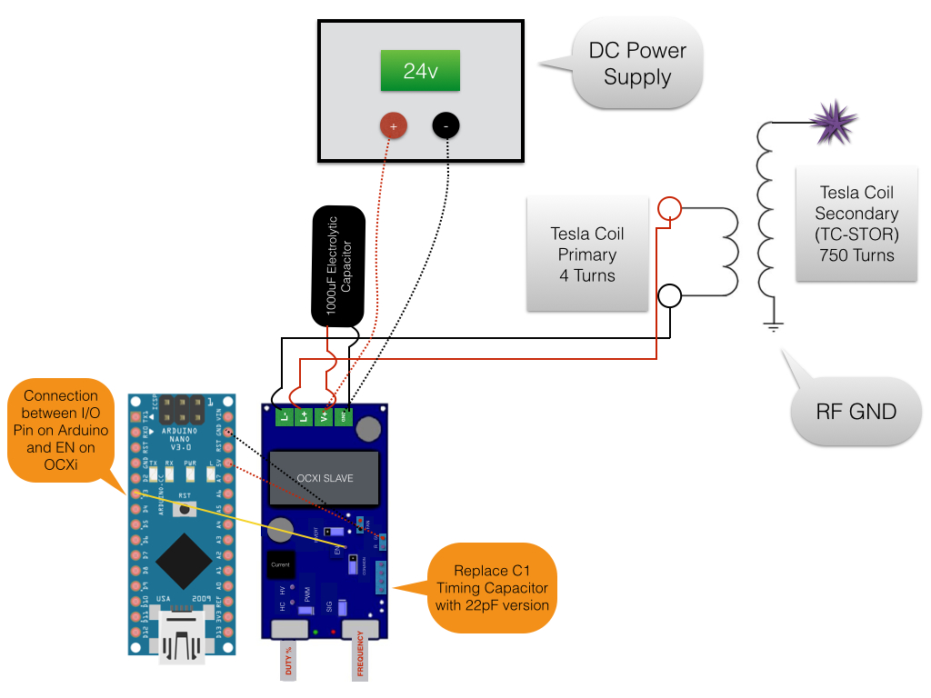
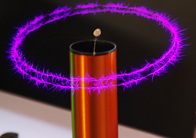 In the videos you can also see a spinning “corona motor”. This is made by simply bending a thin wire into an S shape and making a small loop in the middle so it can be hooked onto a supporting wire. As the plasma forms at the sharp tips of the wire, the air is heated and pushed away giving it some thrust. This will eventually cause the whole wire to spin quite quickly and give this cool looking effect!
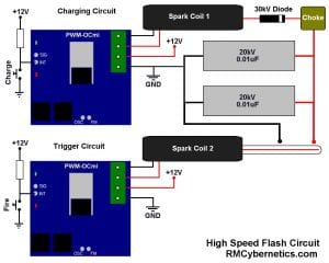 The primary inverter consists of a
 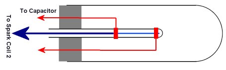 The high speed flash tube consists of two main electrodes on the outside of a small glass tube, plus a third electrode inside the glass tube so that it is isolated from the others.
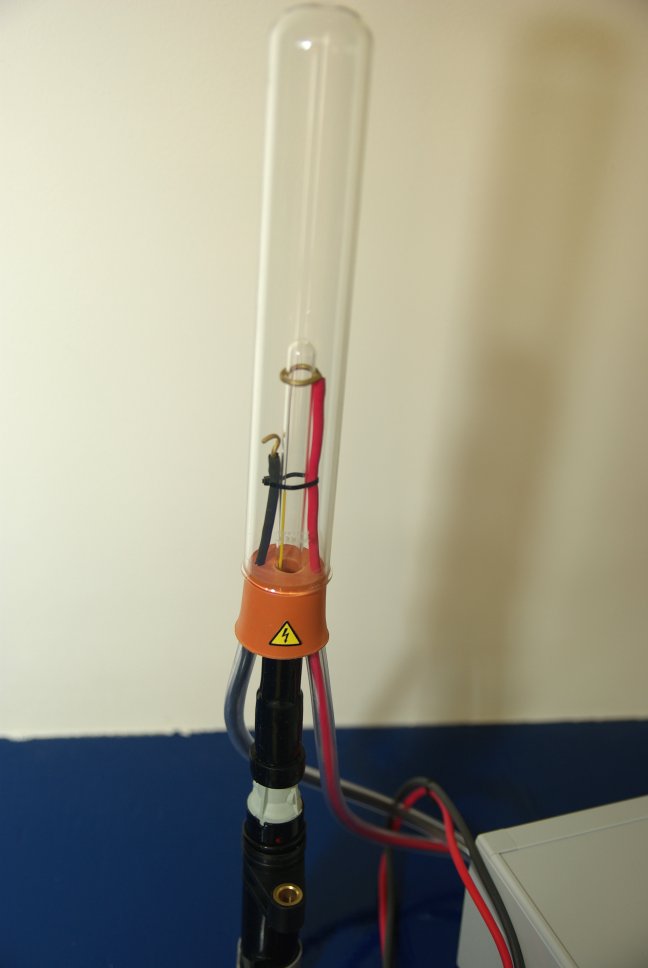
 This article will cover the initial stage of creating a system so that the robot will be able to get around and avoid obstacles. This requires a basic system for motor control, and also for reading and interpreting sensor information. The processing for this will be done using an Arduino Uno which is an open source electronics prototyping platform using an ATmega328 micro-controller. This has the advantage of being simple to program and interface with. There are also many code libraries available on the Internet which people have shared for making programming of common tasks even more simple.
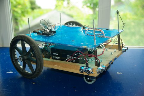
 The chassis for this robot is quite large and heavy because we intend to add much more to it later. This weight meant that the wheels should not be directly connected to the gearbox output shaft on the motor. Instead they were mounted on separate axles with a couple of bearings so that the weight is taken by them instead of the motor. If you want to replicate this part of the project, it could be done with a tiny robot as the Arduino and sensors are very small and lightweight.
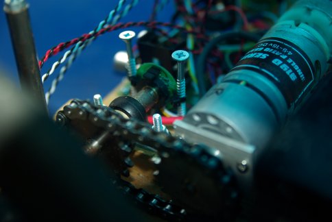 To the end of each axle is a rotary encoder. It was originally fitted to the motors shaft, but at a count of 64 pulses per turn, and a gearbox of 148:1, we felt that 9472 pulses per turn of the wheel was an unnecessary overhead for the small processor. The encoders were instead placed directly on the axle so that it would give 64 pulses per wheel rotation.
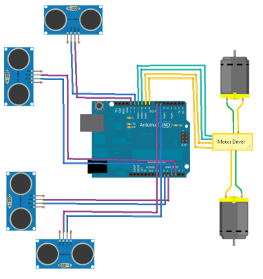 The robot is powered by two 12V SLA batteries. One battery supplies power to the control electronics, while the other is used to power the actuators (motors). By having separate batteries, the high drain from the motor will not interfere with the accuracy of the sensors and control system. The battery for the control electronics feeds into a pair of voltage regulators (5V and 12V) so that the control electronics and sensors have the right voltage levels sent to them.


 Ceramic Standoff
 Current Meter
 12V 15A Power Supply
 12V Water Pump
 Choke
Choke Cooling Radiator
 35A 100V Transistors
 Silicone Pipe
 TO-220 Heatsink
 240 ohm Resistors
 Fast Diodes
 Polypropelene Capacitors
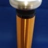
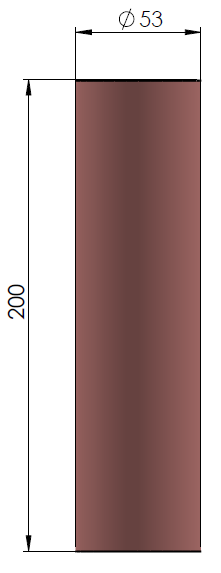
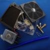
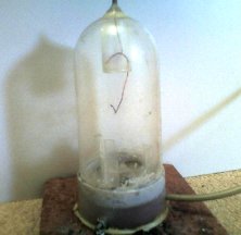 This is very simple to construct, and is made from low cost materials. The main chamber its self is the display case from a popular aftershave.
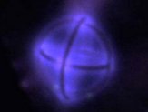 This image shows the centre electrode of an asymmetrical dipole. This arrangement allows particles to be accelerated to a central point from all directions and is often used in experimental fusion rectors. Advance fusion reactors use toroidal (dohnut shaped) vacuum chambers known as a Tokamak