Our popular power PWM control circuits use a single transistor to pulse all sorts of loads for power control. The pulses control current in one direction only which is fine for most PWM applications. However sometimes it is required to have a bi directional pulse for driving an AC load such as a transformer.
Ideally a dedicated H-bridge circuit would be used, but it is possible to approximate this using a pair of our PWM circuits being controlled with an Arduino.
Using our Arduino library NanoPWMac we can drive two circuits with a pulse that is equal in length, but with only one circuit active at a time.
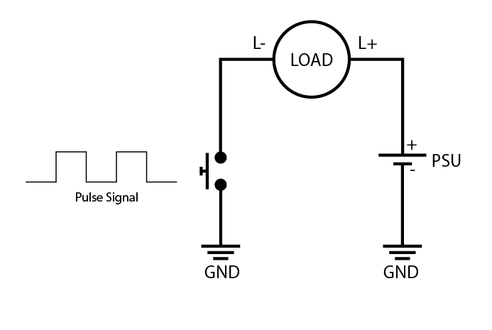
Below you can see a simplified diagram of what is happening with a normal single transistor PWM circuit. The pulse signal basically switches power on/off to the load by making and breaking the path for current from the PSU through the load.
Our PWM modules can be linked directly in a master/slave arrangement (see datasheet) so that when one is on, the other is off and visa-versa. This can be used to drive a transformer with AC, but it only really works if you want a 50% duty cycle. This is because if you set the master PWM to 10%, the other one will be 90% therefore driving the transformer unequally and not allowing for proper power control.
To dive a coil with AC and adjustable duty, an Arduino can be connected to two PWM circuits as shown below. The coil must be centre tapped so that each PWM will pull current in opposite directions.
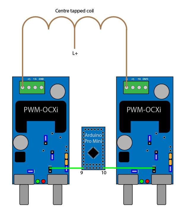
For simplicity the power connections are not shown in the diagram. To link the Arduino to the PWM modules, the SIG jumper is removed from both modules, and a connection from the Arduino pins 9 and 10 is made to the SIG pin marked with a stripe on the OCXi.
The example program in the nanoPWMac library will take a reading from potentiometers connected to A4 and A5 so that these pots can be used to vary frequency and duty independently.
With this setup you can now pulse both circuits in opposition with a waveform like shown below.
Scope Screenshots