FerroFluids
Ferrofluids are made from a suspension of tiny magnetic particles in a liquid such as water or oil. Such a mixture creates a liquid that can be attracted by a magnetic field. NASA discovered Ferrofluids at one of their research centers in the 1960’s while they were looking for different methods of controlling liquids in space.
 The magnetic materials used are often made from iron or cobalt particles, but compounds such as manganese zinc ferrite are also used. The most common form of ferrofluid is made using particles of a type of iron oxide known as magnetite (Fe334). Making a stable Ferrofluid is not quite as simple as mixing tiny particles into a liquid. First of all the particles must be very small. The average size is around 10nm (0.00000001 meters). These particles can not be made by crushing or grinding a material, but are precipitated out of a solution during a chemical reaction.
During the precipitation the particles would naturally amalgamate (come together) due to magnetic and Van der Waals forces. To prevent this the mixture is heated so that thermal motion of the magnetite particles prevents them from sticking together. In order to prevent the particles from amalgamating after the reaction they must be kept apart from each other. This can be archived by coating each particle with another material known as a surfactant (surface active agent) to produce electrostatic or steric repulsive forces between the particles.
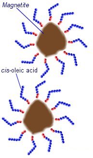
In an oil based ferrofluid, cis-oleic acid can be used as a suffricant. This is a long-chain hydrocarbon with a polar head that sticks to the surface of the magnetite particles. The long molecules stick out in all directions around each magnetite particle preventing them from getting close enough to stick together.
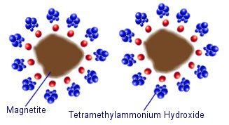
Water based (aqueous) ferrofluids often use ionic sufficants such as tetramethylammonium hydroxide. The negative hydroxide ions stick to the surface of the magnetite, and the tetramethylammonium cations form a positively charged layer around the outside. This means that the magnetite particles are held apart by the electrostatic repulsive force of the surrounding molecules.
 Ferrofluids have several uses due to their magnetic properties. They can be used inside a magnetized bearing like an o-ring seal so that rotating shafts can pass from high to low pressure zones and vise versa. This is a much more efficient method than using solid seals as there is significantly less friction. This makes them ideal for use in submarines, rotating anode x-ray machines, disk drives, and vacuum chambers with external manipulators.
A more every day use of ferrofluid is in high quality loudspeakers. The fluid is pored into the magnetic cavity so that it surrounds the coil. This acts as a thermal conductor allowing more heat to be dissipated so that the speaker can be used at higher power. The fluid also helps to damp unwanted resonant vibrations giving an better overall sound quality.
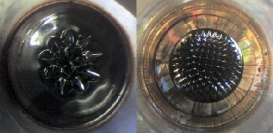
These images show some ferro fluid in a container with a strong magnet placed underneath. The leftmost image shows a few large spikes that are formed as the magnet approaches the container. The other images show a large number of tiny spikes produced by the intense field of a magnet up close.
The spikes form in a manner as if they are following the field lines. In a stronger magnetic field there are more filed lines hence more spikes in the ferrofluid.
If you try this yourself make sure you don’t need the container again as the ferrofluid is very staining.
Video Clips
This Video Clip shows how the spikes of fluid change as a magnet is brought closer and then taken away again. This force is so strong that a normal heavy object such as a penny would appear to float on the fluid because displaced by the liquid moving underneath.
This Video Clip shows how the spikes of ferrofluid over a magnet change as a the magnetic field is oscillated using a coil surrounding the container. Its is possible to tune the vibrating fluid to resonance causing a fine jet to be ejected upwards from the centre. The electromagnetic coil is being powered by a PWM-OCX
Magnetorheological Fluid
 A Magneto-rheological fluid is similar to a ferrofluid in the way that there are magnetic particles suspended in a fluid medium. This type of fluid does not use nano sized particles, but they must be small enough to remain suspended in the liquid. They are typically 2 or 3 times larger than the particles in Ferrofluids and are on the micrometer scale.
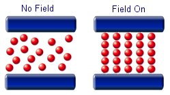
The particles in a magnetorheological fluid are magnetically polarisable. This means that when an external field is applied the micron sized particles will line up and form chain like structures. the alignment of the particles will increase the viscosity of the fluid.
A simple magnetorheological fluid can be made at home. Micron sized ferrous particles can be collect from sand or lake beds. By placing a magnet in a plastic bag and dragging it through sandy sediment many particles will be separated out. Turning the bag inside out and removing it from the magnet prevents the particle from becoming permanently stuck to its surface.
These particles can be mixed with a small amount of oil such as vegetable oil. By holding a magnet to the outside of t he container and poring off excess oil you will be left with a basic magnetorheological fluid. This fluid will not remaining stable for long periods due to the lack of a suffricant, but it serves well to demonstrate the scientific principles involved.
Magnetorheological fluids are being used mostly for controlled damping of oscillations. They are ideal for use in the suspension in large vehicles. In its liquid state it will provide limited damping, but when a magnetic field is brought near to the fluid it will greatly dampen any oscillations. This means that a large mechanical force can be controlled with a much smaller mechanical force.
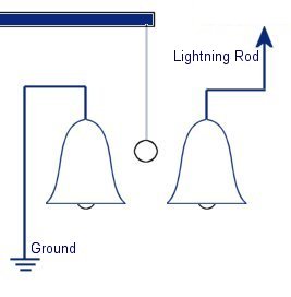 In 1752 Benjamin Franklin was experimenting with one of his inventions, the lightning rod. Using the setup shown on the left Franklin was able collect electrostatic charges from the wind above his house. No known images exist of the original setup used, but this is the most common method used to reproduce the effects he describes.
 This setup was used by Franklin to collect electric charge for use in other experiments. The amount of charge collected was sometimes so faint that after a spark between the bells it would take considerable time to charge up again. At other times a continuous stream of sparks could be obtained even at lengths of around 20cm.
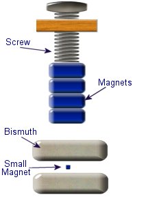 Diamagnetic materials are those that will repel magnetic fields. Many common materials such as water are diamagnetic, but the effect is usually so weak that only super strong magnetic fields will cause any noticeable effect.
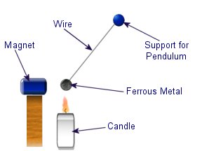 The curie effect usually refers to a magnetic phenomenon discovered by Pierre Curie. He discovered that ferromagnetic substances exhibited a critical temperature transition, above which the substances lost their ferromagnetic behaviour. This is now known as the Curie point.
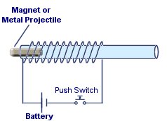 This experiment is a simple way of demonstrating the distribution of the field inside a solenoid and how it effects ferrous metal objects.
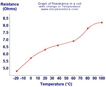 The temperature affects the dimensions of the conductor; a higher temperature causes an expansion in a material while a colder temperature causes a contraction. And with this expansion/contraction a change in resistance occurs as a thicker wire has less resistance to current flow than a thinner one. Materials used as conductors typically tend to increase their resistance with a temperature increase while insulators have the adverse effect. Materials used as insulators often only exhibit a drop in resistance at very high temperatures meaning they usually don’t encounter temperatures high enough though typical use. Because of this these changes cannot all be attributed to the change in dimensions. In fact the resistance change is mainly due to the temperature affecting the atomic structure of the material, causing a change in the resistivity of the material.
 Any normal conductor will see a drop in resistance with a drop in temperature. With a small range of temperatures like shown here the effect is almost linear. The wiggles in the graph are due to inaccurate data generated by the measurement process.
 A DIY Tesla Coil Tuner
 I used two other alligator clips to make a 6 inch jumper to short the spark gap for primary testing.
 Calibration:
 Secondary Fo: To test the secondary’s fundamental frequency, simply connect the TCT between the ground and the base wire from the secondary as shown below. Slowly turn the frequency through the range until the brightest spot is found. The lowest and brightest frequency spot is the fundamental. You may see the dimmer 3rd harmonic at ~3 x Fo. It is probably best to test the secondary frequency on the coil in the actual configuration since the secondary frequency is sensitive to the surrounding objects.
 Primary Fo: To test the primary circuit’s frequency, simply connect the TCT across the primary cap and short the spark gap with the jumper. Slowly turn the frequency through the range until the dimmest spot is found and read the frequency on the dial. You may want to remove the secondary coil to prevent the secondary from affecting this test.