Lasers and Interference
Diffraction and Interference
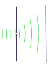 Diffraction is the phenomenon where waves can be bent around obstacles. When coherent light passes through a fine slit some of the rays are diffracted. The varying levels of diffraction cause part of the beam to interfere, thus producing an interference pattern.
Light from most sources is incoherent. This means that the many waves coming from the source do not line up with each other, or are not in phase. Common sources of light such as the sun or a light bulb emit photons at random intervals, but as there are so many overall we see it as just a constant source.
Lasers provide a source of coherent light due to the way that they work. All the wavefront’s emitted from a laser line up with each other. We can use this source of coherent light to demonstrate interference from diffraction in by a single slit.
If the beam from a laser is shone through a fine slit, such as that between the edges of two razor blades, we can easily see how the waves are diffracted and produce interference. If the light from the slit is projected onto a paper screen we can observe and measure the patterns produced.
![]() This phenomenon is related to Huygen’s Principle. This says that every point on a wave front acts as a source of tiny wavelets that move forward with the same speed as the wave. The wave front at a later instant is the surface that is tangent to the wavelets.
This phenomenon is related to Huygen’s Principle. This says that every point on a wave front acts as a source of tiny wavelets that move forward with the same speed as the wave. The wave front at a later instant is the surface that is tangent to the wavelets.
Refraction and the Spectrum
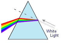 When light enters a denser medium is effectively slowed down. This is due to the light being repeatedly absorbed and re-emited by the atoms in the material. This slowing of the wavefront’s causes the beam to be bent at an angle dependent on the material and the wavelength (colour) of the light.
This image shows how white light is split into its component parts using a prism.
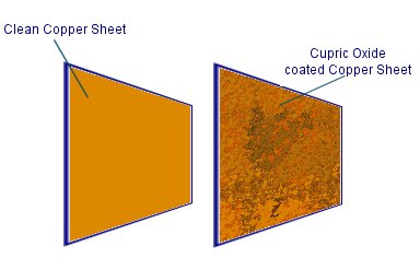 One sheet of copper is given a coating of cupric oxide as this semiconductor will convert sunlight into electricity. To do this a copper sheet is heated over a hob for around 30 minuets. When the sheet has turned black it is allowed to cool. As it cools down the black copper oxide will start to crack up and come off. this is because the materials underneath are contracting at a different rate. it is usually necessary to finish removing some of the black copper oxide by hand.
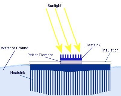 They are commonly used on processors as they can move heat away from a source under electrical power. When connected to a DC power supply a peltier element will heat up on one side whilst becoming cold on the opposite side. A large heatsink is necessary to dissipate the excess heat so that the other side can remain cold.
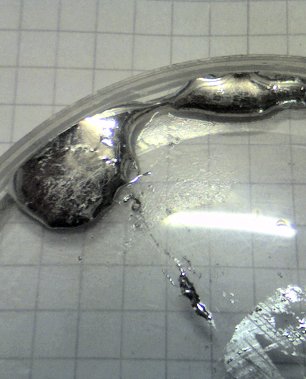 Most metals are a tough solid material at room temperature, but some metals can be liquids. The most obvious one is the element Mercury, which has a melting temperature of -38.83 °C. When certain metals are mixed together they can form what is known as an alloy. The atoms of the various metals will bond together to form the new metal which may have unique properties. Below you can learn how an alloy can be made at home which will melt in hot water. The alloys melting temperature is less than that of any of the original metals.
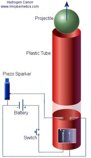 This experiment demonstrates the splitting of water into Hydrogen and Oxygen by electrolysis, and the re combining of these elements in an energetic reaction.
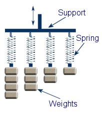 This experiments is a simple way to demonstrate the principles of resonance and simple harmonic motion.
 We will see the maximum displacement when the frequency of the moving support is the same as the resonant frequency of one of the weights. For example; If the resonant frequency of the first mass and spring is 10Hz then it will move the most when the support is moved up and down at 10Hz. This is known as resonance. If the support is moving at 9Hz or 11Hz then there will be significantly less movement of the mass. This is because resonance usually occurs when the frequencies match almost exactly.
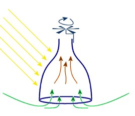 Thermal updrafts are a natural phenomenon produced by localised heating of air. This causes air to rise and fall in relatively small localised areas.
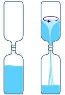 Water Vortex
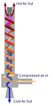 Vortex Cooling
 Plasma Vortex