SHM Resonance
Resonance and Simple Harmonic Motion
 This experiments is a simple way to demonstrate the principles of resonance and simple harmonic motion.
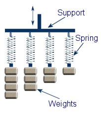
This diagram show four identical springs attached to a support. Each spring has weight with a different mass attached to the end. If a weight is pulled and released, it will set it in motion bouncing up and down until all its energy is dissipated through friction. As each spring holds a different mass, they will each have a different fundamental or resonant frequency. The first spring with the most mass will bounce slowest. We say that this has the lowest resonant frequency out of the four springs. The frequency is simply the number of times the mass bounces up and down each second and is measured in Hertz (Hz).
If the support holding the springs is moved up and down at a set speed, we will see the weights begin to move up and down buy different amounts. The amount of displacement of each mass will be dependant upon the frequency that the support is oscillating at.
 We will see the maximum displacement when the frequency of the moving support is the same as the resonant frequency of one of the weights. For example; If the resonant frequency of the first mass and spring is 10Hz then it will move the most when the support is moved up and down at 10Hz. This is known as resonance. If the support is moving at 9Hz or 11Hz then there will be significantly less movement of the mass. This is because resonance usually occurs when the frequencies match almost exactly.
The exact same principles are used in radios and televisions in order to tune into a specific station. Instead of oscillating springs, it is the electrical currents that are oscillating. By using different components it is possible to make a circuit that has a resonant frequency that is the same as the radio wave that we wish to detect. At resonance the amplitude of the signal in the circuit will be much higher than any of the other signals which allow us to use just one channel at a time.
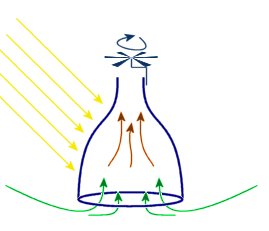 Thermal updrafts are a natural phenomenon produced by localised heating of air. This causes air to rise and fall in relatively small localised areas.
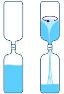 Water Vortex
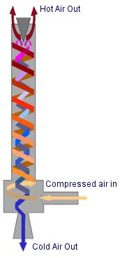 Vortex Cooling
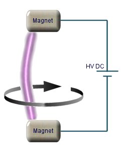 Plasma Vortex
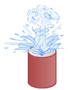 This experiment demonstrates how a substance can change from a liquid to a gas in an instant! A cup of hot water will immediately explode when a small amount of a very cold alcohol based substance is added. Great care must be taken when performing this experiment, and the cold liquid should be added remotely or from behind a safety screen.
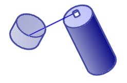 This is done by holding the nozzle in the plastic lid or similar container like shown on the left. The button is then pressed lightly so that the spray starts to come out slowly and collect in the lid. The first bit of liquid will probably evaporate quickly, but as the lid cools down it becomes easier to collect. The amount to collect will depend upon how big the cup of water is and how long it takes to go from collection to adding it to the water.
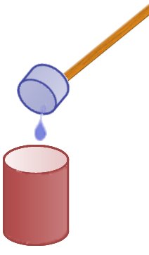 vaporate before any violent reaction can occur.
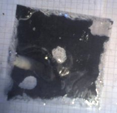 The reflective film used to make one way windows can react quite violently to high DC voltages. The image on the left shows a piece of window film after being exposed to around 30kV from a low current voltage multiplier.
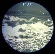
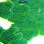
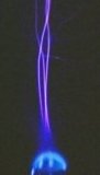
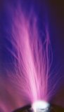
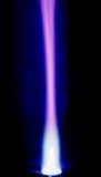 These images show how the electrical hot plasma from the Tesla Coil blends with the cold plasma of the flame. Click on the photos for a full view.
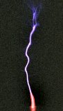
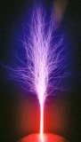
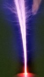 These photos show what happens when pure Neon gas is emitted from the top sphere of a small Tesla Coil. Neon has a much lower ionization voltage than air, so the gas will glow very brightly creating a plasma column to allow the arcs to be much larger. The picture on the right looks similar to the ‘death ray’ devices used in the movie War of the Worlds! You can see when tuned correctly the individual filaments tend to form multiple helices, allowing the plasma column to rise quite high.
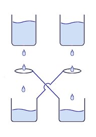 This is a device is a simple method for generating a high voltage charge or static electricity. It works by dripping water through an arrangement of metal containers and loops of wire.
 You can see from the image on the right the way that the H2+ is more on one side therefore making an uneven distribution of charge i.e. a dipole. This is what gives water all its interesting properties such as its powerful solvent abilities and its ability to stick to other materials.
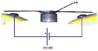 The plastic disc is non conductive, so in order for the charge to get to the other electrode (of opposite polarity), the disk its self must turn. This physical transportation of charge still constitutes a current flow, even though the current does not flow within the material itself. The flowing current is directly proportional to the speed of the rotating disc.


