01270 747 008 (UK)

ZB3245TSS Pick & Place User Manual

ZB3245TSS Pick & Place User Manual

Unofficial Manual by RM Cybernetics
Using Software “FlyerSMT V2.0”

Due to the lack of detail in the official Zheng Bang manual and the inconsistent naming of variables/settings, we created this guide to help clear things up and make it easier to get on with. This is not a full manual and is just intended to supplement the manual and instructional videos from Zheng bang.

Please note that we are an end user of this machine and we do not offer any support whatsoever for this machine. If you need technical support, you should contact ZhengBang directly. Feel free to add comments and questions regarding this manual using the form below, but please do not email us for support, or expect us to help solve any issues with your machine.

Tips for Getting Started

If the software is in Chinese, you can open the software directory and edit the ZB3245TSS.ini file. Look for the line “LANGUAGE=0” and change it to “LANGUAGE=1". Open the software again and it should now be in English.

The machine can move very fast which will cause it to shake. You should mount it on something very sturdy. We used a large solid wood table which was also bolted to the wall securely. If you fail to secure the machine, the vibrations could affect the accuracy.

Read the official manuals, watch their videos, then read this article.

Setting up the Feeders

One of the first things you need to do with any Pick & Place machine is to set up the feeders with the components you will be using to make a PCB. Each feeder has an associated number and you must tell the software some information such as its position in the machine, and what sort of part it holds. You also set up additional parameters such as what sort of vision check to use or which nozzle to use for picking up the part.

The video below is from Zheng Bang
https://www.youtube.com/watch?v=SclsnNz4sSk

There’s a lot of parameters to edit so this can be time consuming, when first setting up, but once it is done, you do not need to do much here unless changing parts in a feeder. Below you can find a table of all the parameters and what they are used for. Assume that all text parameters that you can edit are case sensitive.

When we first began this part, we had some difficulty with the nozzle and feeder pin being offset so had to sort that out first. That is discussed later in a section about calibration.

Feeder Setup

Setting

Function

Enable On/Off

Enable or disable the feeder. When enabled, information about this feeder will populate the lower table.

No.

The feeder ID number
Select “+Goto” to Enable/Disable moving the camera to the feeder when selected

Value

Unique Component Value. Type it or select <. > to browse components already added. Your placement CSV file should use these values under the 7th column.

Package

This is the component package type such as 0805, SOIC-8, and so on. The value is case sensitive. Your placement CSV file should use these values under the 2nd column.

Coordinate

The X,Y position of the component centre in the feeder. Press Update to open the dialog for moving and saving the camera position. Your placement CSV file should use these values under the 3rd and 4th column.

Distance/Sum

This is the space between each part in the tape. This is typically 2mm or 4mm for small components.

Hole/Offset

This is the position of the hole in the tape used to index the feeder.

Angle

The angle of the part in the feeder

Nozzle Height

The distance in mm the nozzle must move down to contact the part. This should always be about the same since the feeders hold the tape top surface up to the same height.

Thickness

The overall thickness of the component

Take Speed

The speed at which the reel is pulled to reveal the next component

Paste Speed

The speed at which the head moves down to place the part

Nozzle

Select which nozzle(s) can be used with this part.

Vision ON/OFF

Check the part was picked up correctly or use vision to align it.

Type

Select the type of vision check to use from the options below;


NULL


1feet / 2feet / 3feet


TwoRowIC / FourRowIC


BGA


High LED


Currency

This appears to be the common bottom vision checking to check the size, offset, and angle of a small part such as a resistor.

Size

X/Y size of the part in mm. This will be calculated automatically by the vision system.

Threshold

Adjusts the light/image threshold for detecting the part against the background. You can use Auto, or set it manually.

To register

This button is used to automatically measure the part using the vision system. If “+with Chip” is selected, it will pick up a part, move over the camera, measure it, and then update the Size field.

Camera / Nozzle goto

Moves the machine head to the coordinates of the selected feeder. You can choose to either have the camera over the coordinates (for checking if things are in the right place), or to have the nozzle move over the component so that you can test picking it up.

1#Nozzle / 2#Nozzle

Send the nozzle down to the part. Holding the button keeps the nozzle down, otherwise it goes back up.

ThrowHoldTime


Step Feed

Step the feeder to reveal the next part. This will only work if you have the feeder all set up correctly.

Tight Film

Tighten the film peeled off the tape.

Chip Drop

You can press “chip drop” when finished measuring a part and it will go drop the part in a small tray near the front right of the machine.

OK

Saves the changes and returns to the “Edit” menu.


Setting up a New PCB Product

There does not seem to be a simple way in the GUI to just begin a new product. Therefore, you must make a copy of an existing product file, rename it, and then load that into the software. You can download a sample product file and CSV file from here for reference. TODO MAKE FILES.

The file containing all the information about the PCB product has a “.H8” file extension. After opening the file in FlyerSMT, you must remember to press the save button for any edits to be saved to the file. It is probably wise to make a copy of the file occasionally in case you need to revert to an older save.

This file contains all the saved data including the feeder setup, PCB size, and list of components.

If you export a CSV file from your PCB design software for the pick and place machine, it should have the columns ordered as follows.

Name

Type

X

Y

Layer

Angle

Val

Just your part designator or reference. This is not used by the software directly

Footprint such as “0805”. This is used by the software to match your CSV data to the feeder

X co-ordinate in mm

Y co-ordinate in mm

UNUSED? Always should be “T”

Placement angle in degrees

Component value such as “10k”. This is used by the software to match your CSV data to the feeder

The names of the columns in the CSV file are not important as when opening the file, the first row is simply ignored. Only the order of the columns determines where they will load in the software.

You can import a CSV file and edit it within the software. When you press the save button for the CSV file, it opens a “save as” dialog asking you where to save the file and with what name. However, when saving, it will use its own column titles regardless of what yours were when importing the CSV. Due to a bug in the software, these do not all actually associate correctly with the data below them. You can still use the file and import the data, but it can be confusing to read in Excel as the column titles are mismatched and some additional ones are added.

The naming conventions throughout the software are rather inconsistent which can make it really confusing when setting up and editing. Basically, in your CSV file, there should be two columns which contain values used to match your CSV to a feeder.

·         The first column (Name/Designator) is just for reference and does not affect the feeder choice. 

·         Column 2 (Type/Footprint) must match the feeder data “Package”.

·         Column 7 (Comment/Val) must match the feeder data “Value”.

In the Product menu, when you click “Matching”, the software will check your CSV data against the feeder data looking for any feeder that matches both the footprint and value fields. Where there is a match, it will apply that feeder number to your PCB data, otherwise it will just show NULL.

ZB3245TSS-product-image

Zheng Bang ZB3245TSS Pick & Place Machine

ZB3245TSS-product-imageWe purchased a small Pick and Place machine from China for doing small batch runs and prototypes. This post is to document the experience of buying and setting up a ZhengBang ZB3245TSS Pick & Place Machine. The company offers several other models, but we chose this one as it has 58 possible feeder slots meaning we could keep almost all the standard SMD components we usually use in the machine.

Spoiler Alert: Our machine came with malware preinstalled which was able to infect any USB device plugged into it! It appears that this was an oversight by Zheng Bang, rather than any deliberate action. This will be discussed later in the article.

We ordered the machine on AliExpress at a total price of about £4k GBP excluding import duty. It arrived just before we shut down for Christmas so it sat for a week before we had chance to look at it. It came pretty well packed in a large wooden crate and needed two people to lift it out of the box to put it in place.

Zhengbang Machine Delivery Automatic SMT Vision Pick and Place Machine ZB3245TSS Packing

There was not really much to plug into the machine to get it started. Basically monitor, keyboard, mouse. When switched on the machine would boot very quickly into Windows 7 Ultimate. When asking the supplier if we could update it to W10, we were told that it would stop the machine from working. A little disappointing since this is a brand new machine and W7 has been out of support since Jan 2020. 

The machine came with two aluminium bars and a round rod which were not mentioned in the manual or videos. Support told me it is to hold the larger reels and sent a photo. Unfortunately it seems they sent the wrong part as there is no way for those parts to fit to the machine meaning at this point we are stuck being able to use only smaller reels. They have told us they will send out the correct part to us.

Being a machine direct from China and at relatively low cost compared to a branded competitor product, our expectations were to have to do a little work to get going with it and work around the typical Chinese product bugs and flaws. Much of the OS and other software on the machine was in Chinese which is a bit of a pain, but the main operating software was in English (well, sort of). 

Opening the software called FlyerSMT_HV brought up an unsurprisingly crude looking interface, which homed the machine without any difficulty. We have used pick and place machines before so are familiar with their operation so had a quick look around at the settings and controls. They seemed familiar enough though the English words used to describe them are a little hard to understand. Well there’s always an extensive user manual to refer to right?… Right?

ZB3245TSS-FlyerSMT_HV-software Zhengbang-FlyerSMT_HV-software

Zhengbang ZB3245TSS User Manual

There was a desktop shortcut on the machine to an English user manual for the machine. There was also a video file demonstrating basic setup. The first pages of the manual show all the parts and buttons labelling what they are called, though only what they are called and rather little about what they may do. For example, there’s a big button on the side of the machine called “FAST BOOT”, and in the manual this is pointed at with a label saying “Fast Boot”… and that’s it! One might guess that this was some sort of fast start-up for the machine, though with it booting from an SSD it was pretty rapid anyway. If you also guessed the same, you would be wrong. We had to ask the supplier what it does as nothing in the manual or videos describes it. We were told “Fast Boot is a button ,if you done finished one time placement,then click this button ,it will directly to placement another PCB.” 

One of the first things to do with a pick and place machine is to set up the feeders with your components. There is a section about this in the manual, but again it is very vague and we had to contact support to clarify some points. You might expect that each of the input parameters would be described in the manual, but unfortunately they are not. The bad English makes it even harder to figure out. Support sent us a selection of YouTube videos with some guidance which did help. 

Preinstalled Malware

At this point we felt we could at least get started editing feeders and setting up so the software on the machine was backed up to a USB stick in case we messed anything up. When plugging this USB into one of our workstations, the AntiVirus immediately popped up saying it was disinfecting the drive! Looking at the log showed it to be the file “FlyerSMT_HV.exe” which is the main operating software for the machine! This file was uploaded to VirusTotal to get an idea if it may be false positive result. VirusTotal told us that 53 out of 69 AV products flagged it as malware. Zhengbang support were told about this and they told us it is a false positive and not to worry as there is AV software installed on the machine. We were sent a new zip file with the software in it. The contents of this zip file did not flag up as containing malware.

zhengbang-virus

We sent the file for malware analysis which did confirm that it did indeed contain malware. The malware would collect user data and send it to a remote address. Presumably it could be a way to steal company information such as designs, accounts, and so on, or to install ransomware on other machines. Pretty shady stuff! However, it doesn’t end there!

With the new, uninfected software from Zhengbang, we thought we can just replace the infected one and try again. That seemed to work ok, and we also copied over a few malware removal tools to the machine to make sure. When putting the USB back into a workstation, up pops Bit Defender again, but now flagging up the installers for tools we had just downloaded! They were all showing as having the same infection as FlyerSMT_HV. How could these be infected as they were from legitimate sources and did not flag up when originally downloaded?

After scanning the embedded PC in the Zhengbang machine, with several different AV tools, we discovered more malware including trojan downloaders. This malware would make a hidden copy of any exe on the USB stick, and then re-pack it with some included malware. Clever stuff! 

Lots of scanning and manual work eventually has the machine showing up as not infected and the USB devices are no longer being infected. W7 has been updated as far as it can be too, and so far it appears OK. Really though it would be better to replace the SSD with a legit English copy of windows and re install only the software needed. However we will need to make sure we have a copy of all the necessary drivers and so on to get it going again.

The machine shipped with a copy of Windows 7 Ultimate installed and with updates disabled. This version of windows is very common as pirate software and would often come bundled with malware in such downloads. It could be that this is the source for the malware and Zheng bang were unaware or just didn’t care. I would have expected as company that they would check this as they could end up with their own systems at the factory compromised. Since publishing this article, it has been read thousands of times and has come to the attention of Zheng Bang themselves. Initially they asked us to delete the article, but over the Chinese New Year holiday, it has been shared widely on various websites around the world. It became so popular for a time that our server could not cope with the traffic. They have now posted a message on Hackaday where the article was shared. The message is as follows;

I am with Zhengbang, on behalf of our company, we are sorry Richard did not get a good shopping from us.

I checked his blog, the virus he got name is Synaptics.exe as we can saw from blog picture, we can google it, it’s very famous and bad one, . I can say though Zhengbang is number one table top PNP machine factory in China, we donot have the technical strength to develop this kind of malware. We have alibaba and aliexpress stores and some of them are our
agents’.

It’s hard to tell where got this virus maybe my colleague or suppliers unexpected and accidentally got it during production, but it’s our fault did not find out before deliver it to client. We are just a normal businees company never try to steal any information from clients.

My colleague is still communicating with Richard after sent him new software, hope to solve this and hope his company can put our machine in use soon.

We feel this is a positive if belated response from Zhengbang as they accept the ultimate responsibility for it. We would now hope that they will be making sure any machines they build will be free of any viruses.

AliExpress took no action

We contacted Ali Express to report that machines were being sold with preinstalled malware, but their response was not forthcoming. They stated that it does not breach their terms and that no action will be taken. While it may not be against their policy, we know that it is against UK law according to the computer misuse act. Deliberately infecting systems using subterfuge to access computer data without permission is a criminal offence. So there you have it, if you want to sell machines with malware for illegal means, Ali Express appear to be unwilling to stop it! Below is their reply to us…

“Please be informed that the reported listing(s) is / are neither prohibited nor controlled item(s) under our Product Listing Policy.”

We have seen a lot of comments on other sites linking to this article and much of the focus is on the malware being on a new machine. We feel that though disappointing, it is not entirely unexpected as Chinese suppliers are well known for malware, fake goods and low quality. More significant should be the fact that AliExpress LTD, a company registered and operating in the UK have chosen to ignore the fact that their website is being used for something illegal.

There have been a few other comments questioning why we appear to be keeping the machine rather than returning it. First of all, it was cheap and we expected to have issues with it. There is nothing else equivalent (that we are aware of) in this price bracket other than more Chinese machines. If you ever bought something from AliExpress or other direct from China stuff then you will know to lower your expectations significantly. It’s not running on our network, and now has a new SSD & legit OS installed so the risk of further infection is minimal. The hardware seems reasonably sturdy and we are hopeful we can make good use of it. That said, if it turns out that we cannot reliably build PCBs with it, then of course we will be looking for a refund. We are a teeny tiny company of just one and a half humans. COVID has caused all sorts of issues leaving us just limping along so we really want to get this machine going and try to get some things made.

Installing Clean Software

We replaced the SSD with a new 256GB mSATA drive and replaced the 2GB RAM module with a 4GB stick. We were told, that the system will not work on Windows 10, but we wanted to at least give it a try and see if there was anything we could do to get it working. We cloned a clean Windows 10 64-bit installation to the SSD which booted up fine and found most of the drivers. The LAN driver was not picked up, so we had to download this from Gigabyte on a another PC and transfer it by USB. Once online, it was fairly straightforward to install the remaining drivers for the motherboard.

The Zhengbang ZB3245 pick and place machine vision cameras are analogue cameras connected to a small PCIe capture card in the built in PC. The capture card in our machine is a Goldvision HV4000 which appears to be a fairly old bit of kit and we could find no legitimate support or drivers for it online. The original hard drive did have a copy of the drivers which we were able to install, but only after disabling driver signature enforcement in windows. Installing the drivers seemed to make the machine blue screen and we have not been able to get any images form the cameras.

The virus-free copy of Flyer_SMT.exe would not run initially as error messages pooped up about missing DLL files. These were common Visual Studio files, so we installed the VCC Redistributable pack from Microsoft and then tried again. The software loaded up, and was able to home the machine normally so appeared to be fully functional apart from the vision cameras. If at some point we find a way to get them to work in W10 we will post here, but at this point we decided to install a clean copy of Windows 7 Pro. We opted for dual boot with a separate partition so that we could go back to the W10 installation if needed later.

Installing Windows 7 32-bit on a new machine felt kinda wrong, but it only has one job to do so it doesn’t matter a great deal as long as it works and stays malware free. The process was similar, though for some drivers we needed to look up the hardware IDs on the PCI database to find the drivers. Once it was all installed the software ran OK, but again no cameras. We contacted Zhengbang support and were told to remove the HV4000 capture card and clean the contacts. This appeared to work, and the system now seems to be operational. However, we booted W10 to have another look if the card would work there now, but it didn’t show up in device manager. When going back to W7, the card was not showing up, and there was no working vision again! We discovered that if the machine were powered off at the mains, and rebooted direct to W7, the HV4000 card would reappear. Weird.

Inside the Zhengbang ZB3245TSS pick and place machine

Opening the machine is fairly simple with a few hex bolts around the top perimeter holding the heavy work area down to the base. With these removed, the top lifts up with hinges at the back and there’s a handy bar inside to hold it up. The hinges at the back do look rather undersized for how heavy the top is, so take care if you open one of these machines!

ZB3245TS Insides

Inside is quite neat and tidy with the PC inside the black box in the rear left. The PC appears to have an HDMI port and I/O for audio, so if you wanted a different screen, or some audio, this would be possible. 

Inside a Zhengbang machine
Component Overview
Zhengbang Industrial PC
Zhengbang Motion Controller

Once we had the system working, We cloned the SSD to an old hard drive using an Acronis bootable USB. Plugging the hard drive into the USB3 ports via a SATA/USB adaptor didn’t work as it just caused the ports and therefore the keyboard/mouse to stop working. We had to use a SATA dock with independent power supply and this worked fine. With the system working, backed up and virus free, we could now get on with adding reels to the feeders.

Adding Component Reels

We are at the point where we can start adding parts (apart for the larger reels due to the missing bits). We will update this article as we go along and add as much useful info as we can for anyone else with such a machine.

We’d love to hear your feedback if you used one or have any suggestions for things like getting the Goldvision HV4000 capture card to work in W10.

Induction Heating

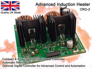
Guide to Induction Heating

This page will discuss the practical side of induction heating to help you understand how to make use of it and how to optimise your system. Induction heating is a method of non-contact heating using high frequency electromagnetic fields. Induction heating only works on electrically conductive materials and the efficiency at which electrical power is converted to heat will vary significantly with different materials.

Heating a Steel Nut Red Hot
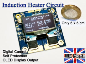
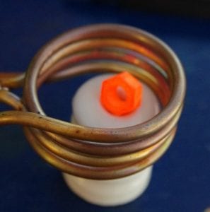
An induction heater heating a steel nut red hot

How does induction heating work?

The heating effect works by inducing a current to flow in a material by exposing it to an alternating magnetic field. This alternating magnetic field is typically in the kHz range and is created using a resonating coil.

When the induced electrical current flows in a material, heat is generated through resistance losses and also hysteresis losses in ferromagnetic materials like iron. Typically, the easiest materials to heat will be of relatively high resistance (but still a conductor), and be ferromagnetic like iron. Low resistance materials like copper and silver can be very hard to heat with induction. When melting silver, for example, it is usually best to heat a graphite crucible and place the sliver inside. This is because graphite is easy to heat with induction and it will then heat the silver indirectly.

One advantage of induction heating is that only the metal parts will be heated and you could, for example, heat a metal part that is totally sealed within a glass container without directly heating the container its self. Other advantages of induction heating include safety (flameless heating), precision, and efficiency.

Working with our induction heater systems

We offer a range of induction heating components for sale which can be used to create a wide range of projects and experiments. Below you will find information to help you get the most out of these and to help you to understand your induction system. We also offer custom electronics design services and consultancy for if you need help making a specific project.

Micro Induction Heater Circuit

Induction Heater Circuit

Transferring Heating Power from the PSU to the Workpiece

In order to deliver maximum power to a work coil, they are driven at their resonant frequency. Doing this minimises power loss in the driving circuitry and maximises efficiency. The work coil also has a parallel capacitor which forms the other part of an LC resonant tank circuit. Some induction heater systems use a series resonant capacitor and coil, but in this article we will discuss the parallel resonant systems. When being driven at its resonant frequency, energy builds up in this LC tank leading to very high currents. This means that although you may be drawing, for example, 10A from your power supply, there could be 30A or more flowing back and forth between the capacitor and work coil at very high frequency. Because of this, it is important to consider those currents when designing a work coil for your induction heater system.

Simplified Induction Heater Diagram

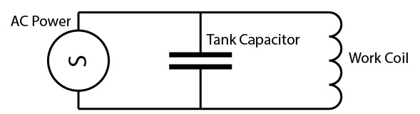
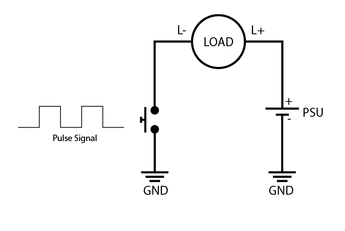
Figure 1: Simplified Induction Heater

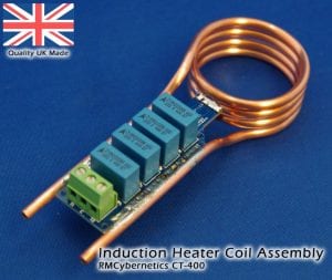
It is also important to consider how adding a piece of material into the work coil will alter the amount of power drawn by the system. When the coil is resonating without any workpiece, the current draw from the PSU will be relatively low, but once something is added, it can rise significantly. How much it rises will depend on the total mass, the material from which the workpiece is made, and how close the windings are to the material. For example; in one of our CT-400 coils running from a 15V supply and a driver circuit (such as our CRO-SM2), the current draw could be about 3.5A from the PSU when nothing is in the coil. If we add something like an M6 steel bolt, the current draw will rise to over 10A. Yet if we inserted an M6 stainless steel bolt, the current draw would only rise to around 5A. There would also only be a small change when adding a material like copper. More about the effects of different materials is discussed later.

Also affecting the rise in current when adding a workpiece is the magnetic coupling. A large coil and a small workpiece will show only a relatively small rise in current, whereas a small coil surrounding the same workpiece would allow the current to increase significantly. When adding ferrous materials like Iron, the magnetic coupling is increased and this makes them much easier to heat. However, when such materials reach a high temperature, they will lose their magnetic properties due to something called the Curie Effect. At this point you may see the PSU current drop, and it will become more difficult to increase the temperature further.

The rise in current from the PSU when adding a workpiece to the coil is an excellent indicator of how effective the heating will be. It is therefore important to balance all these factors when considering a coil design for a particular induction heating project.

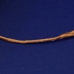
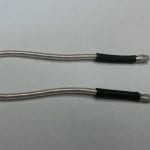
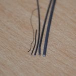
Another important consideration is parasitic elements in your circuit. These are small elements of inductance, resistance and capacitance that are not deliberately chosen to be there, but are a product of the physical nature of components (such as the connecting wires). Since these parasitic elements can cause losses and interference, it is important to reduce or control these as much as possible. A simple parasitic element would be the resistance of the metal in the wire or pipe used to make a work coil. This resistance will cause the coil its self to heat up when current flows in it so it is important to minimise this loss by using thick, high-quality wire. Another issue to consider is the skin effect. This is a phenomenon where high frequency currents tend to flow mainly on the outer surface of a conductor. This means that if using ordinary wire to make a work coil, a large amount of the conducting copper is never actually used and it therefore has a higher parasitic resistance. The skin effect can be minimised by using specialist cable known as Litz Wire. This has multiple insulated strands of wire twisted together to prevent the current being pushed to the outer surface. You can find Litz wire for sale in our shop. Sometimes it is not practical to use Litz Wire so it is common to use copper pipe as water can be pumped through it to keep it cool. This is typically the best method when heating things red hot as the radiated heat from the workpiece would melt the insulation in a litz wire.

The parasitic resistance in a work coil will cause the coil to heat up, waste power, or even overheat and melt. Another effect the resistance has is to reduce the Q factor of the resonant tank. This is important as the current resonating in the tank is roughly the input current multiplied by the Q factor. The parallel capacitors also have some parasitic resistance so it is important to choose ones that not only have a low resistance (known as ESR), but also capable of handling high currents at high frequencies. A common method of minimising parasitic ESR is to use an array of smaller capacitors connected in parallel so that the current is shared between them and the resistance is reduced overall. We have a range of suitable induction heater capacitors for sale in our shop.

Parasitic Resistance

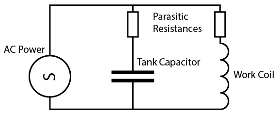
Figure 2: Parasitic Resistance in an Induction Heater

Another important parasitic element is inductance. Any current carrying conductor will have some inductance which causes a resistance to change in the current flowing in the circuit. In an induction heater, this can both be useful, and harmful, depending where in the circuit the inductance is.

The LC tank circuit has a specific resonant frequency at which we drive it for maximum efficiency. However, other small inductances and capacitances in the connecting wires also have natural resonant frequencies that may differ from that of the LC tank. This can create harmonic frequencies which trick the driver circuit in to oscillating at the wrong frequency, or a mixture of several frequencies.

A ZVS driver like our CRO-SM3 and CRO-2 can be vulnerable to latching onto parasitic oscillations, so it is important that the layout and connections between the work coil, tank capacitor, and driver circuit are made carefully.

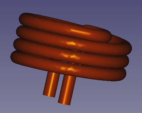
Long leads between the driver circuit and the LC tank will create significant parasitic inductances. Consider that a typical work coil like our CT-400 may only have 100cm of copper pipe making up the whole coil. If you have 25cm connecting wires between the CT-400 and the driver circuit, this adds another 50cm of conductor with an inductance of its own. This inductance is not part of the LC tank as it is before the tank capacitor so any resonance from it will be detrimental to the system.

Parasitic Inductance

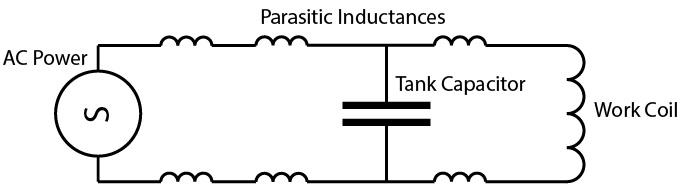
Figure 3: Parasitic Inductance in an induction heater

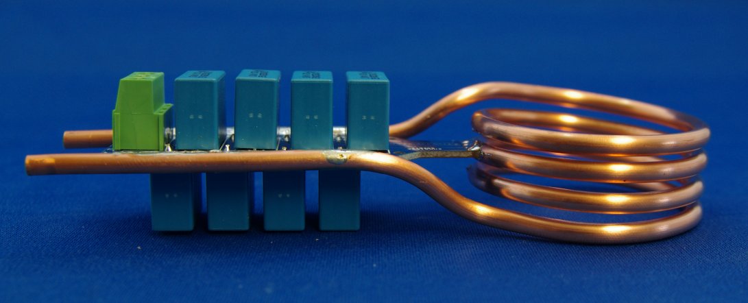
If we move the tank capacitor to the other side so it sits between the connecting wires and work coil, the problems with mixed frequency resonances will be mostly eliminated as the inductance of the wires now basically forms part of the work coil. However, this means that those connecting wires will also carry the same high currents as the work coil and will heat up if they are not suitably large. In a water-cooled coil this can be quite impractical to do.

It is possible to mitigate some of the parasitic resonance by adding more tank capacitance at the output terminals of the driver circuit, between the circuit and the connecting wires. This can reduce the high frequency ringing cause by the leads and help the driver to lock on to the correct frequency.

Split Tank Capacitor

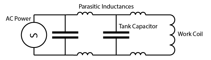
Figure 4: Split Tank Capacitor to compensate for long leads

There are also parasitic inductances and capacitances in the driver electronics themselves. These can be much harder to deal with as they are mostly just part of the physical nature of the components. These parasitic elements become much more significant when driving very high frequency coils, and much less so at low frequencies.

In all cases it is necessary to make trade-offs in the system design based on what is practical, the power requirements, target frequency, efficiency, and cost. If you need any help working out what is the best way to approach your system design, please get in touch.

Induction Heater Coil Design Tips

The work coil design is critical for achieving maximum performance in any induction heating project. While a simple work coil like our CT-400 will suit a range of applications, if you want to make use of every watt, then the work coil must be designed to suit your project.

There are a few fundamental work coil shapes commonly used in induction heating. Their shape is chosen to maximise coupling and power transfer to the workpiece as well as being practical to use.

The first thing you should consider when looking at an induction heating project is the power requirements. To heat a known mass of material in a known time is relatively easy to calculate. You can use our handy heater power calculator to get a rough idea. When using this you should consider the efficiency of the power transfer from PSU to heat in the workpiece, and also the heat lost as IR radiation. A hot metal part will be radiating a large amount of heat into the atmosphere if it is not insulated. If we are melting jewellery in a graphite crucible, the entire thing can be insulated making for a very efficient process. If we are heating stainless steel in open air, then we not only have the low power coupling, but also the radiated losses to consider.

Custom Helical Coil Custom Pancake Coil

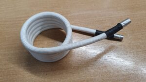
Helical Induction Coils
A typical cylindrical shape coil that creates a heating field within the inside of the cylinder. These are easy to make and will transfer power efficiently to materials within.

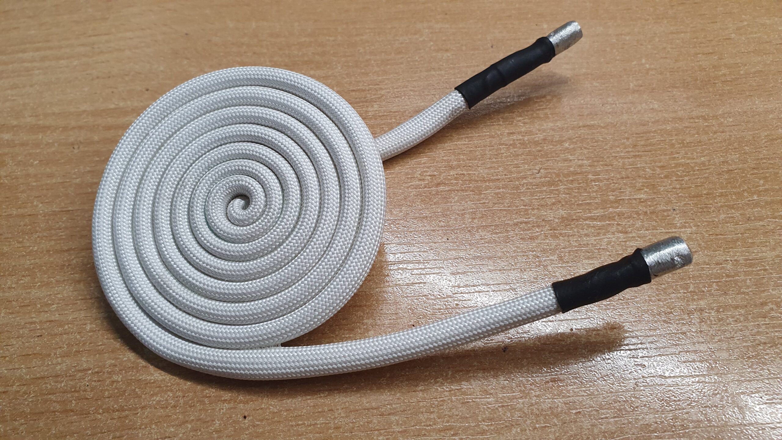
Pancake Induction Coils
Commonly used in induction cookers as they offer good coupling to the base of the saucepan. To be effective, the workpiece (like a saucepan) must be very close to the coil.

U-Shaped Induction Coils
These are basically a pancake coil that has been folded over. They are common for induction hardening of blades as it is easy to pass the blade through the coil while limiting the heating to only the edge.

There are many other sorts of induction coil shapes, often custom made just for one specific application. Please feel free to get in touch or post a message below if you want to discuss a custom induction heater coil design.

The work coils job is to transfer power from the system PSU to the workpiece (material being heated). Generally speaking, we look at the combined coil and workpiece as a single transformer with the work coil being the primary coil, and the workpiece being a secondary coil (consisting of just one turn). We can use this approximation when making calculations as the current flowing in the secondary coil of a transformer is proportional to the current in the primary coil multiplied by the number of turns. While this sounds simple, it can be more complex in practice as we also must consider the resistivity of the workpiece and the electrical impedance of the work coil.

In a typical helical (cylindrical) coil the magnetic flux density is not homogenous throughout its volume. Most of the flux is concentrated near the outer edges of the volume within the coil. This means that if placing a small part in a large coil, it will absorb more power if placed within the inside edges rather than in the centre of the coil. There is also a lower flux density at each end of the coil. When the workpiece is made from a ferrous material, it will actually change the way the lines of magnetic flux form within the coil, dragging them into itself and improving coupling. If heating something made from multiple materials, this effect should be considered as the flux may be diverted into or away from the other materials.

Induction Heating Different Materials

Which material works best for induction heating? The material a workpiece is made from will significantly affect its ability to rise in temperature within a high frequency magnetic field. Here we will compare a few materials and discuss how we can optimise our system to get the greatest heating effect. Iron typically works best in an induction heater with a power transfer of more than 90%. Copper on the other hand, will only make use of around 15% of power in the system. We typically think of metals being heated with induction, but other materials that can be heated too as long as they are significantly electrically conductive, but also have some resistance.

The main factors influencing the heating efficiency are magnetic coupling and resistivity. While heating due to resistance losses is proportional to I2R, this does not always translate directly in an induction heater system. For example, copper has a low resistivity and could therefore have a high current flowing within the material. However, the impedance of the driver limits power that can be delivered, while to current flowing in the copper will create a back emf in the work coil, also limiting the input power.  

An important factor to consider when heating larger volumes, is the thermal conductivity of the material. As high frequency induction heating only heats the outer surface directly (due to the skin effect), the remaining mass of material is heated mainly by the internal conduction of heat from the surface. In larger induction furnaces, lower frequencies are used so that there is deeper penetration of the heating currents.

Below you can find a table of a few common materials and some of the relevant properties that may be considered when used in induction heating.

Material Resistivity ρ (μΩ•m) at 20 °C Relative Permeability μ / μ0 Heat Capacity (J/g C°) Density g/cm3 Thermal Conductivity W/(m K)
Iron 0.1 5000 0.449 7.85 80
Stainless Steel (316) 0.74 1.004 0.502 8 16.3
Stainless Steel (304) 0.72 1.6 0.5 7.982 16.2
Nickel 0.0699 325 0.461 8.902 92
Tungsten 0.056 1 0.132 19.45 174
Copper 0.0168 0.999 0.385 8.96 386
Cobalt 0.056 60 0.435 8.9 69
Titanium 0.42 1 0.523 4.52 17
Graphite 3.75 0.999 0.717 2.66 247
Brass 0.7 0.999 0.375 8.565 96
Gold 0.0244 0.999 0.129 19.32 310
Silver 0.0159 0.999 0.235 10.497 419
Aluminium 0.0282 1 0.897 2.705 239
Tin 0.109 1 0.218 7.26 67
Zinc 0.059 0.999 0.377 7.068 113
Lead 0.022 0.999 0.129 11.29 35

Table 1: Important parameters of materials when used in Induction heating

* Values can vary significantly depending upon the exact composition, crystal structure, orientation, frequency and temperature. Where a range of values was given in the source, the value here is the average.

Data in this table is collated from numerous sources including those found below:
https://www.engineeringtoolbox.com/specific-heat-capacity-d_391.html
https://www.engineersedge.com/materials/specific_heat_capacity_of_metals_13259.htm
https://sciencenotes.org/table-of-electrical-resistivity-and-conductivity/
https://www.electronics-notes.com/articles/basic_concepts/resistance/electrical-resistivity-table-materials.php
https://www.azom.com/article.aspx?ArticleID=2868
https://www.engineeringtoolbox.com/permeability-d_1923.html
https://onlinelibrary.wiley.com/doi/pdf/10.1002/9781118936160.app2
https://theengineeringmindset.com/density-of-metals/
https://www.angstromsciences.com/density-elements-chart
https://www.sciencedirect.com/topics/engineering/thermal-conductivity-coefficient
https://www.researchgate.net/figure/Relation-of-relative-permeability-of-304-and-316-at-a-low-magnetic-field-strength-and_tbl1_2696949207

Iron (Nickel & Cobalt too)

Iron is an excellent induction heating material for several reasons. Iron is a ferromagnetic material which basically means it is attracted to magnetic fields and thus pulls the magnetic field lines towards it creating a higher concentration within. This basically increases the magnetic induction field strength and creates a high level of magnetic coupling between the coil and workpiece. Good magnetic coupling means an efficient power transfer from the system to the workpiece being heated. Ferrous materials can be magnetised like the way you can magnetise a screwdriver tip by passing it by a magnet. In a high frequency induction field, the material is being magnetised in one polarity and then another, over and over. This creates further heating through hysteresis losses. However, once iron gets really hot, it will reach the Currie Point and these magnetic advantages disappear. After this it is the resistance losses that will be driving any further increase in temperature. Iron has a relatively high resistivity (it doesn’t conduct well compared to copper wires), and this increases with temperature. This high resistivity means that more heat is generated by the induced currents as the heat generated is proportional to I2R (current x current x resistance).

Stainless Steel

Stainless steel can be heated by induction, but compared to mild steel or iron, it has some significant disadvantages. Being only very slightly magnetic, there is a low amount of coupling between the coil and workpiece, so it is important that the work coil form is close to the shape of the part being heated. It does however have a high resistivity which also increases with temperature so this does help it to generate heat from induced currents.

Carbon

Carbon is an interesting material for induction heating as it is a non-metal, yet can conduct electricity. It has a high resistivity compared to metals which actually helps in the heating process making it much easier to heat than stainless steel. Other forms of carbon such as graphite, graphene, and even diamonds can be heated with an induction heater. Carbon is much less dense than many metals and therefore the same volume of carbon would heat much more quickly than a metal part the same size. This low density is what makes it a lightweight material and means that it will take less energy to raise or lower its temperature for a given volume.

Graphite Crucibles
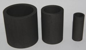
Graphite crucibles used for induction heating

Tin & Tungsten

Tin and Tungsten have a high resistivity and will heat well in an induction heater field. Tungsten however is extremely dense and therefore has a large heat capacity. Being very dense, it has a small volume for a given mass which means within the same sized work coil, it will intersect fewer magnetic field lines than a material of lower density such as Tin.

Copper & Aluminium

Copper and Aluminium can be heated in an induction heater, but the efficiency of doing so is very low. As good conductors of electricity, their low resistivity means lower resistance losses from the induced currents. However, like other metals, the resistivity increases with temperature and heating becomes more efficient as it gets hotter.

Precious Metals (Gold and Silver)

Silver being the most conductive element is extremely hard to heat directly with an induction heater. To heat precious metals, it is usually best to place the metal within a graphite crucible so that the magnetic field heats the crucible, and this transfers the heat to the metals via conduction and IR radiation.

Other Non-metals

There are a number of non-metals that can be heated with induction. This can be semiconductors, ferrites, and other compounds.

Ferrite Nanoparticles
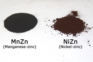
Ferrite Powders used for Induction Heating

Ferrites have multiple uses in induction heating. MnZn Ferrite can be used for magnetic shielding or to guide the path of magnetic flux. Others like NiZn ferrite can be mixed into materials and heated up like metal. NiZn nanoparticles can be absorbed by biological systems and then heated by external fields. This allows heat to be delivered inside certain cells, but without heating the whole lifeform.


Custom induction heater circuit

Interconnected PWM

Bipolar PWM with Arduino

Our popular power PWM control circuits use a single transistor to pulse all sorts of loads for power control. The pulses control current in one direction only which is fine for most PWM applications. However sometimes it is required to have a bi directional pulse for driving an AC load such as a transformer.

Ideally a dedicated H-bridge circuit would be used, but it is possible to approximate this using a pair of our PWM circuits being controlled with an Arduino.

Using our Arduino library NanoPWMac we can drive two circuits with a pulse that is equal in length, but with only one circuit active at a time.

Below you can see a simplified diagram of what is happening with a normal single transistor PWM circuit. The pulse signal basically switches power on/off to the load by making and breaking the path for current from the PSU through the load.

Our PWM modules can be linked directly in a master/slave arrangement (see datasheet) so that when one is on, the other is off and visa-versa. This can be used to drive a transformer with AC, but it only really works if you want a 50% duty cycle. This is because if you set the master PWM to 10%, the other one will be 90% therefore driving the transformer unequally and not allowing for proper power control.

To dive a coil with AC and adjustable duty, an Arduino can be connected to two PWM circuits as shown below. The coil must be centre tapped so that each PWM will pull current in opposite directions.

For simplicity the power connections are not shown in the diagram. To link the Arduino to the PWM modules, the SIG jumper is removed from both modules, and a connection from the Arduino pins 9 and 10 is made to the SIG pin marked with a stripe on the OCXi.

The example program in the nanoPWMac library will take a reading from potentiometers connected to A4 and A5 so that these pots can be used to vary frequency and duty independently.

With this setup you can now pulse both circuits in opposition with a waveform like shown below.

Litz Wire

Litz Wire

What is Litz Wire?

Litz wire is a type of cable formed by combining multiple strands of thin insulated wire together side by side. It is used to carry high frequency currents as the insulated strands each carry a portion of the current and prevent losses due to the skin effect. Litz wire is commonly found in radio frequency (RF) applications, and high frequency power circuits such as induction heaters and Tesla Coils.

The strands in litz wire are typically twisted together either as a single bunch, or as multiple bunches twisted to form a large cable. By twisting the wires together it helps to control the magnetic fields around the wires and keep the currents flowing evenly.

Litz Wire

Litz Wire

2.1920.74Select options This product has multiple variants. The options may be chosen on the product page

Litz Wire Soldering

Litz Wire Soldering

11.0116.23Select options This product has multiple variants. The options may be chosen on the product page

Tungsten Wire

Tungsten Wire

8.1017.37Select options This product has multiple variants. The options may be chosen on the product page

What is the skin effect?

She skin effect is a term given to the phenomenon of when high frequency currents tend to flow near the surface (or skin) of an electrical conductor. This occurs due to magnetic fields being induced in the conductor by the changing currents. The magnetic fields make it difficult for the currents to flow anywhere but the outer surface.
 
With the currents being forced to flow in just part of the conducting wire, the effective resistance of the wire is greater. The higher the frequency, the more loss in the wire due to this resistance.
 
By using this skin effect calculator, we can see that at a frequency of 1MHz, the effective skin depth is just 65μm (0.065mm), while at 1kHz, the effective depth is 2062μm (2mm) in a copper wire. 
 

How to make litz wire

Using common magnet wire it is possible to make your own litz wire by twisting it together in bunches. It is not practical for large numbers of strands but is doable for short lengths with a small number of individual wires.

The simplest way is to cut equal lengths of the required magnet wire and to clamp or tie all of one end together. The other ends can be put in the chuck of a hand drill which is used to twist them tightly together.

How to solder litz wire

It can be very difficult to solder litz wire as they can contain thousands of individually insulated strands. It is necessary to remove this insulation before soldering can take place. This can be done by first burning the end to be soldered and then cleaning of the burned insulation with wire wool. Doing this without breaking the fine strands or leaving some of them uncleaned can be quite challenging.

The best way is to use a hot solder bath as this can both burn off the insulation and add the solder. The solder bath must be quite hot and it works best if the litz wire is first dipped into flux to help the solder to stick.

Where can I buy litz wire?

We have a range of litz wire sizes for sale and offer soldering services for ready to use litz cable assemblies. If there is a specific size you need that we do not stock, we can custom make it to your requirements.

Lasers and Interference

Diffraction and Interference

Diffraction through a slit
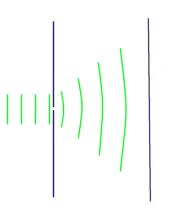
Diffraction is the phenomenon where waves can be bent around obstacles. When coherent light passes through a fine slit some of the rays are diffracted. The varying levels of diffraction cause part of the beam to interfere, thus producing an interference pattern.

Light from most sources is incoherent. This means that the many waves coming from the source do not line up with each other, or are not in phase. Common sources of light such as the sun or a light bulb emit photons at random intervals, but as there are so many overall we see it as just a constant source.

Lasers provide a source of coherent light due to the way that they work. All the wavefront’s emitted from a laser line up with each other. We can use this source of coherent light to demonstrate interference from diffraction in by a single slit.

If the beam from a laser is shone through a fine slit, such as that between the edges of two razor blades, we can easily see how the waves are diffracted and produce interference. If the light from the slit is projected onto a paper screen we can observe and measure the patterns produced.

interference patternThis phenomenon is related to Huygen’s Principle. This says that every point on a wave front acts as a source of tiny wavelets that move forward with the same speed as the wave. The wave front at a later instant is the surface that is tangent to the wavelets.

Refraction and the Spectrum

refraction in a prism
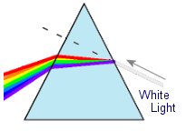
When light enters a denser medium is effectively slowed down. This is due to the light being repeatedly absorbed and re-emited by the atoms in the material. This slowing of the wavefront’s causes the beam to be bent at an angle dependent on the material and the wavelength (colour) of the light.

This image shows how white light is split into its component parts using a prism.

Electricity from Light

Homemade Solar Panels

This shows a simple demonstration of how a homemade solar panel can be used to show the photoelectric effect making electricity from light. Making a solar panel this way would be no where near good enough to generate useful free energy for powering a home, but it great for demonstrating scientific principles.

Solar Panels
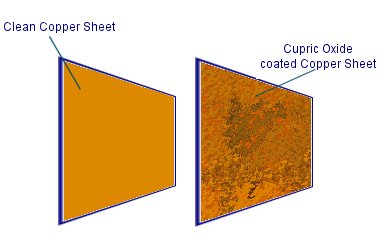
One sheet of copper is given a coating of cupric oxide as this semiconductor will convert sunlight into electricity. To do this a copper sheet is heated over a hob for around 30 minuets. When the sheet has turned black it is allowed to cool. As it cools down the black copper oxide will start to crack up and come off. this is because the materials underneath are contracting at a different rate. it is usually necessary to finish removing some of the black copper oxide by hand.

The remaining layer is covered with cupric oxide which is the important material for producing the photoelectric effect.

If the copper sheets are placed in a strong salt solution in the arrangement shown above, a small voltage will appear between the two sheets. The salt water is really just meant as an electrical conductor, but it also has the effect of making the device operate like a battery. this means it still generates small amounts of electricity even in the dark.

Electricity from Heat

Free Energy from the Environment

This is a simple setup that uses the thermoelectric / seebeck effect for converting heat directly into electricity with no moving parts. There are devices available called Peltier Heat Pumps which are used to keep electronic components cool.

Thermoelectric Generator
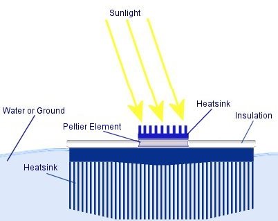
They are commonly used on processors as they can move heat away from a source under electrical power. When connected to a DC power supply a peltier element will heat up on one side whilst becoming cold on the opposite side. A large heatsink is necessary to dissipate the excess heat so that the other side can remain cold.

These peltier elements can also work in reverse. If it is heated on one side whilst being cooled on the other side a voltage will appear across the terminals. As long as there is a temperature difference between the two sides of the peltier device, then there will be a voltage between the electrical terminals.

Peltier heat pumps are not a very efficient method of generating electricity, but at least the supply of energy is free.

In a practical application a large heatsink could be buried in the ground to remove heat. If the peltier element is placed onto this is can be arranged to be heated on one side by the sun. A small black heatsink on the top of the peltier device could be used to collect heat from the sun that has been focused by a large mirror. Another method might be to use a larger heatsink and to place it inside a greenhouse. With this method it would be important to insulate between the hot and cold heatsinks so that the ground would not be heated directly.