ZB3245TSS Pick & Place User Manual
Unofficial Manual by RM Cybernetics
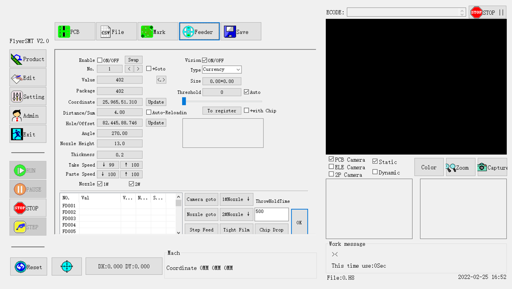
Using Software “FlyerSMT V2.0”
Due to the lack of detail in the official Zheng Bang manual and the inconsistent naming of variables/settings, we created this guide to help clear things up and make it easier to get on with. This is not a full manual and is just intended to supplement the manual and instructional videos from Zheng bang.
Please note that we are an end user of this machine and we do not offer any support whatsoever for this machine. If you need technical support, you should contact ZhengBang directly. Feel free to add comments and questions regarding this manual using the form below, but please do not email us for support, or expect us to help solve any issues with your machine.
Tips for Getting Started
If the software is in Chinese, you can open the software directory and edit the ZB3245TSS.ini file. Look for the line “LANGUAGE=0” and change it to “LANGUAGE=1". Open the software again and it should now be in English.
The machine can move very fast which will cause it to shake. You should mount it on something very sturdy. We used a large solid wood table which was also bolted to the wall securely. If you fail to secure the machine, the vibrations could affect the accuracy.
Read the official manuals, watch their videos, then read this article.
Setting up the Feeders
One of the first things you need to do with any Pick & Place machine is to set up the feeders with the components you will be using to make a PCB. Each feeder has an associated number and you must tell the software some information such as its position in the machine, and what sort of part it holds. You also set up additional parameters such as what sort of vision check to use or which nozzle to use for picking up the part.
The video below is from Zheng Bang
https://www.youtube.com/watch?v=SclsnNz4sSk
There’s a lot of parameters to edit so this can be time consuming, when first setting up, but once it is done, you do not need to do much here unless changing parts in a feeder. Below you can find a table of all the parameters and what they are used for. Assume that all text parameters that you can edit are case sensitive.
When we first began this part, we had some difficulty with the nozzle and feeder pin being offset so had to sort that out first. That is discussed later in a section about calibration.
|
Setting |
Function |
|
Enable On/Off |
Enable or disable the feeder. When enabled, information about this feeder will populate the lower table. |
|
No. |
The feeder ID number |
|
Value |
Unique Component Value. Type it or select <. > to browse components already added. Your placement CSV file should use these values under the 7th column. |
|
Package |
This is the component package type such as 0805, SOIC-8, and so on. The value is case sensitive. Your placement CSV file should use these values under the 2nd column. |
|
Coordinate |
The X,Y position of the component centre in the feeder. Press Update to open the dialog for moving and saving the camera position. Your placement CSV file should use these values under the 3rd and 4th column. |
|
Distance/Sum |
This is the space between each part in the tape. This is typically 2mm or 4mm for small components. |
|
Hole/Offset |
This is the position of the hole in the tape used to index the feeder. |
|
Angle |
The angle of the part in the feeder |
|
Nozzle Height |
The distance in mm the nozzle must move down to contact the part. This should always be about the same since the feeders hold the tape top surface up to the same height. |
|
Thickness |
The overall thickness of the component |
|
Take Speed |
The speed at which the reel is pulled to reveal the next component |
|
Paste Speed |
The speed at which the head moves down to place the part |
|
Nozzle |
Select which nozzle(s) can be used with this part. |
|
Vision ON/OFF |
Check the part was picked up correctly or use vision to align it. |
|
Type |
Select the type of vision check to use from the options below;
NULL
1feet / 2feet / 3feet
TwoRowIC / FourRowIC
BGA
High LED
Currency This appears to be the common bottom vision checking to check the size, offset, and angle of a small part such as a resistor. |
|
Size |
X/Y size of the part in mm. This will be calculated automatically by the vision system. |
|
Threshold |
Adjusts the light/image threshold for detecting the part against the background. You can use Auto, or set it manually. |
|
To register |
This button is used to automatically measure the part using the vision system. If “+with Chip” is selected, it will pick up a part, move over the camera, measure it, and then update the Size field. |
|
Camera / Nozzle goto |
Moves the machine head to the coordinates of the selected feeder. You can choose to either have the camera over the coordinates (for checking if things are in the right place), or to have the nozzle move over the component so that you can test picking it up. |
|
1#Nozzle / 2#Nozzle |
Send the nozzle down to the part. Holding the button keeps the nozzle down, otherwise it goes back up. |
|
ThrowHoldTime |
|
|
Step Feed |
Step the feeder to reveal the next part. This will only work if you have the feeder all set up correctly. |
|
Tight Film |
Tighten the film peeled off the tape. |
|
Chip Drop |
You can press “chip drop” when finished measuring a part and it will go drop the part in a small tray near the front right of the machine. |
|
OK |
Saves the changes and returns to the “Edit” menu. |
|
|
Setting up a New PCB Product
There does not seem to be a simple way in the GUI to just begin a new product. Therefore, you must make a copy of an existing product file, rename it, and then load that into the software. You can download a sample product file and CSV file from here for reference. TODO MAKE FILES.
The file containing all the information about the PCB product has a “.H8” file extension. After opening the file in FlyerSMT, you must remember to press the save button for any edits to be saved to the file. It is probably wise to make a copy of the file occasionally in case you need to revert to an older save.
This file contains all the saved data including the feeder setup, PCB size, and list of components.
If you export a CSV file from your PCB design software for the pick and place machine, it should have the columns ordered as follows.
|
Name |
Type |
X |
Y |
Layer |
Angle |
Val |
|
Just your part designator or reference. This is not used by the software directly |
Footprint such as “0805”. This is used by the software to match your CSV data to the feeder |
X co-ordinate in mm |
Y co-ordinate in mm |
UNUSED? Always should be “T” |
Placement angle in degrees |
Component value such as “10k”. This is used by the software to match your CSV data to the feeder |
The names of the columns in the CSV file are not important as when opening the file, the first row is simply ignored. Only the order of the columns determines where they will load in the software.
You can import a CSV file and edit it within the software. When you press the save button for the CSV file, it opens a “save as” dialog asking you where to save the file and with what name. However, when saving, it will use its own column titles regardless of what yours were when importing the CSV. Due to a bug in the software, these do not all actually associate correctly with the data below them. You can still use the file and import the data, but it can be confusing to read in Excel as the column titles are mismatched and some additional ones are added.
The naming conventions throughout the software are rather inconsistent which can make it really confusing when setting up and editing. Basically, in your CSV file, there should be two columns which contain values used to match your CSV to a feeder.
· The first column (Name/Designator) is just for reference and does not affect the feeder choice.
· Column 2 (Type/Footprint) must match the feeder data “Package”.
· Column 7 (Comment/Val) must match the feeder data “Value”.
In the Product menu, when you click “Matching”, the software will check your CSV data against the feeder data looking for any feeder that matches both the footprint and value fields. Where there is a match, it will apply that feeder number to your PCB data, otherwise it will just show NULL.


I have this machine for a year. Not exactly your model, it changes a bit.
As you said the software is… not sure how to describe it… old, crude, buggy, bad documented, non intuitive, pre windows 95 look and feel.
Im start working in a new software for the machine. Its a desktop machine. I do not need a really full featured one, but a moderm and intuitive one is ok. Cameras resolution in my machine is ok, but procesing may be better, even if it take a bit more time to place the component (wrong aligned component is less than useless).
I worked with vision and opencv before, and software is not complex. However im not sure if anyone tries to manage the machine with other software. Maybe the protocol is really closed.
Anyone interested? or do something like this before?
Some better software would be great though I think it would be a significant undertaking. Zheng Bang will not share any source or other details, so you you would need to work out some things yourself. You could have a look at OpenPnP and see if this can be made to work with the Zheng bang hardware.