-
×
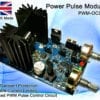
 Power Pulse Modulator - PWM-OCmi (HV)
1 × $52.92
Power Pulse Modulator - PWM-OCmi (HV)
1 × $52.92
Subtotal: $52.92
Power Pulse Modulator - PWM-OCmi (HV)
1 × $52.92 Subtotal: $52.92
High Voltage electricity is a very useful tool for scientific development. In controlled conditions, high gradient fields can be used to develop new technology and discover more about the nature of the universe. Many high voltage phenomenon exist naturally that remain unexplained. Even something as common as lightening is not fully understood or explainable with current
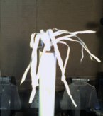
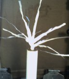
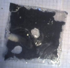 The reflective film used to make one way windows can react quite violently to high DC voltages. The image on the left shows a piece of window film after being exposed to around 30kV from a low current voltage multiplier.
The film is composed of a plastic sheet coated with a fine layer of metal on one side. When placed plastic side down on the top of a voltage multiplier or Van de Graffe generator, it will act in a similar way to a capacitor. If a grounded electrode is placed near to the metal surface the effectiveness of the ‘capacitor’ will increase dramatically until the dielectric material breaks down, or the air breaks down allowing an arc to pass over the the surface of the plastic layer.
When this breakdown occurs the silver material and some of the dielectric are blasted into the air, leaving full transparent patches on the foil. When the film is removed from the HV power supply, it can retain a reasonable charge. The charge can be randomly distributed around the surface and you may still get a zap from a pieces that seem to have been discharged. The best way to tell if a piece is still charged, is to see if is sticks to things. A highly charged piece will be strongly attracted to other surfaces.
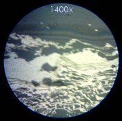
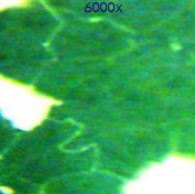
The images above show a microscopic view of the film after it has been violently discharged. The dark material is the metal, and the light is just the remaining plastic. At the top of the left image is the bulk of the metal. Under higher magnification we can see that this area also contains very fine fractures, as shown on the right
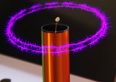
A homemade Tesla Coil is great for special effects style science experiments. The high voltage, high frequency output can cause strange effects in all sorts of materials. The Tesla Coil used in these experiments has a pipe inside the centre of the secondary coil. This pipe allows gas to be emitted from a small hole in the topload sphere.
Fire is a type of plasma, as the constant exchange of electronic bonds between the molecules and the release of energy allows electrons to move around under the influence of an external electric field. Fire is considered as a ‘cold plasma’ because it temperature is relatively low when compared to electrically generated plasmas. A small flame from butane gas emitted form the top of the Tesla Coil acts as a discharge terminal or breakout point. The hot gasses rising from the flame also provide a further conductive channel.
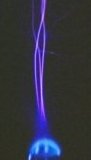

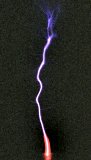
 These images show how the electrical hot plasma from the Tesla Coil blends with the cold plasma of the flame. Click on the photos for a full view.
The rightmost image shows the electrical discharge through a hot jet flame like that of a bunsen burner. This flame causes the arc to stay mostly in one filament until the turbulence becomes too great.
See more photos of plasma on the plasma page
The Noble gasses (often referred to as inert gas) are often used to make plasma because they will not react with the electrodes or surrounding material. Different gas types have different ionization voltages, and will also emit different colours of light.
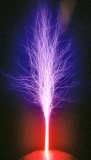
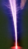 These photos show what happens when pure Neon gas is emitted from the top sphere of a small Tesla Coil. Neon has a much lower ionization voltage than air, so the gas will glow very brightly creating a plasma column to allow the arcs to be much larger. The picture on the right looks similar to the ‘death ray’ devices used in the movie War of the Worlds! You can see when tuned correctly the individual filaments tend to form multiple helices, allowing the plasma column to rise quite high.
See more photos of plasma on the plasma page
We can see from these images that the Neon only helps to increase the length of the plasma filaments when it is still relatively concentrated. The neon is not ‘burnt’ or consumed, but it quickly mixes with the air, and its effects on the plasma become negligible.
The top left video clip shows a TC with a perspex hemisphere loosely covering the top. When Neon gas is emitted from the top sphere it is forced to spread over the surface before escaping. You can see how the neon layer glows red. The next clip of a spontaneous single filament shows the TC in normal operation.
The erratic flowing arcs spontaneously disappear then return as one single extra long arc. The last two clips show how the gas affects the TC when it is emitted directly from the top of the metal sphere
This Solid State Tesla Coil is easy to build, upgradeable and gives great results with only a a little work! This project shows how to make a small Tesla Coil that can run on batteries or any other suitable low voltage DC supply. From as little as 12V input it is possible to make high frequency plasma sparks that even play music! The result of this high voltage, high frequency output is being able to make awesome looking sparks and arcs of plasma in the air.
![]() WARNING: High Voltage Device! High Voltages can be very dangerous!
WARNING: High Voltage Device! High Voltages can be very dangerous!
What is an SSTC (Solid State Tesla Coil)?
What it is and how it differs from a classical Tesla Coil (SGTC) which uses a spark gap.
Like all Tesla Coils, a Solid State Tesla Coil (SSTC) is a type of high frequency resonant transformer which can step up a low voltage DC input into a very high frequency AC output. The main difference between a SSTC vs a SGTC is that the SSTC has no spark gap an instead uses modern transistor technology to switch the current in the primary coil. If you are not familiar with them, check our article on how a Tesla Coil works. There are many forms of SSTC which vary by how the transistors are configured or how the system is resonated. In this version, just a single IGBT is used to switch current in the primary at the resonant frequency of the secondary coil. By using a specialised PWM circuit (our Power Pulse Modulator PWM-OCXi v2) it is possible to tune into the right frequency and then adjust the power level with the turn of a knob.
There are a lot of articles online showing how to make an SSTC, but we like to think that this one must be one of the simplest and most cost effective ways of making one and without compromising on performance.
 How to make an SSTC
How to put the parts together to make a SSTC
If you choose to buy all the parts ready made then it is possible to get this Tesla Coil up and running in around five minutes! Only a few parts are required for this SSTC. These are detailed below along with how to put them together in a number of ways to make a simple mini solid state Tesla Coil.
For this project, you will need;
• Power Pulse Modulator PWM-OCXi v2 (Though it is feasible with only one OCXi, you will get a more stable and prolonged effect result with two!)
• A PSU with a voltage between 12V and 30V with a current of at least 5A. A large battery could also work, but take care not to let the voltage drop below 12V.
• A helical coil of around 750 turns (for the secondary coil)
• 10A (or larger) cable for winding primary coil
• A 1000uF, 50V (or more) electrolytic capacitor
• A 22pF timing capacitor (for the OCXi)
The Secondary Coil
The tall helical coil from which the sparks come
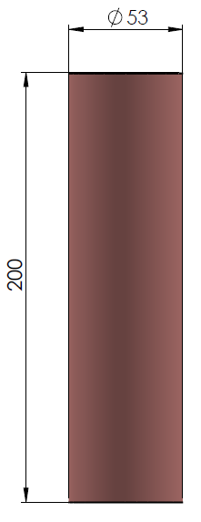 This part can be quite difficult and time consuming to produce yourself. If you do not want to wind your own, check out our helical coils or Tesla Coil Secondary coils which include a toroid. The exact size or number of windings are not critical as long as there is a relatively high number of turns on the secondary coil. Our coils use around 750 turns of 0.25mm magnet wire wound onto a PVC pipe of 53mm in diameter. This coil resonates at around 1MHz.
To make one yourself, find a suitable piece of pipe such as some drainage pipe or any other straight plastic tube that is around 20cm long. Start by fixing the start of your wire to one end of the coil then carefully turn the tube while holding the wire tight so that each turn lays right up against the previous turn. It is important to make all the turns tight and with no spaces or overlapping turns otherwise the coil may not operate efficiently. During winding it can be useful to add a small spot of super glue occasionally so that if you accidently let go, it wont all unwind and leave you with a tangled mess. When using magnet wire (enamel coated wire), it is necessary to scrape off the insulating layer at the ends so that a connection can be made. While this is not so important at the output side, it is essential at the base where there must be a good connection to RF ground.
The HV output will come from the top part of the coil. You should let a small bit of wire protrude away from the main body of the coil so that the electric field will be concentrated around it’s tip. The bottom of the coil must be connected to a suitable RF (radio frequency) Ground. This should not mains ground, or the GND connection of your power supply. This is because the high frequency can cause significant interference with other electronics. A suitable RF GND would be a connection to a metal filing cabinet, or a long metal stake in the earth.
The Primary Coil
Small coil pulsed with low voltage, high current
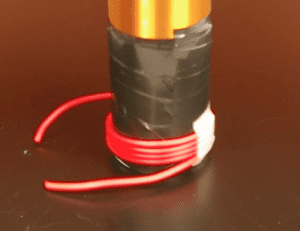 The primary coil simply consists of around four windings of thick copper wire wrapped around the base of the secondary coil. It is best to use something well insulated as it prevents corona leaking energy from the primary coil. In this example we used 10A silicone insulated wire as it is highly flexible, well insulated and easy to work with. Before coiling the primary winding onto the secondary coil, we wrapped a folded piece of A4 paper around the bottom and then coated the paper with insulating tape. This just helps to protect the fine secondary windings and also reduce corona leakage.
The ends of the primary coil connect directly to the PWM-OCXi’s output terminals (L+ and L-). The length of connecting wire between the OCXi and the base of the coil should be around 10cm. If it is too long, the extra inductance and resistance might reduce the performance of the SSTC.
 The SSTC Drive Circuit
Connecting the PWM-OCXi to the primary coil and PSU
It is possible to just use a single OCXi drive circuit to make this work, but this will run the SSTC at a continuous 1MHz. While this will make a great silent plasma plume, it is really hard work for the IGBT in the circuit which means it will quickly heat up and could be damaged if allowed to get too hot. When used in this way it is sometimes refered to as a Continuous Wave SSTC (CWSSTC) due to the fact that the output is a continuous 1MHz high voltage waveform.
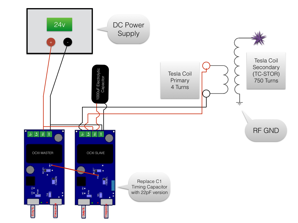
It is best to use one OCXi tuned to power the primary coil at 1MHz and then another OCXi (or another low frequency source) to modulate its output. By doing this we can make short 1MHz pulses that create a large spark while not dissipating too much heat over time in the IGBT on the OCXi drive circuit. The OCXi driving the coil will need to have the timing capacitor (C1) replaced with one rated for 22pF so that the frequency range is at the top end.
The diagram shown here shows two OCXi circuits in a Master/Slave setup. The circuits are powered from the same supply and a short wire is connected between the master’s DRV connection and the slave’s EN connection. More details about the master/slave setup can be found in the OCXi datasheet. The slave device is set to power the primary coil at 1MHz with around 50% duty, while the master OCXi is set to around 100Hz and 10% duty. Each time the master OCXi pulses high, the slave circuuit is momentarily activated. The resultant sparks look as good as they would with only one OCXi, but at only 10% of the power used!
It is important to connect a large capacitor such as a 1000uF 50V electrolyitic capacitor close to the power input terminals of the circuit driving the primary coil. This is used to help supply the high current pulses to the coil as a PSU or battery would not be able to do this alone.
![]() DANGER: This device will create a lot of radio frequency interference!
DANGER: This device will create a lot of radio frequency interference!
Operating the Solid State Tesla Coil
Tuning and running the SSTC
First of all make sure it is set up in a clear space, and it is not near any sensitive electronics. This can cause a lot of interference with nearby electronics such as computers and phones. When doing this project, one of our computer screens around 10m away from the system would flicker when it was running! It would also cause significant problems when trying to make footage of this on our DSLR camera. Interference would reset the camera, or even corrupt the memory cards.
Before powering on the circuits, ensure that the duty setting of the slave OCXi is set to 0% while the frequency is set to maximum. If also using a slave circuit, set its duty to about 10% and the frequency to minimum.
Turn down the lights and then turn on the power to the circuits and slowly turn up the duty on the slave unit to around 50%. Watch the tip of the secondary winding for any glowing purple discharge and SLOWLY adjust the frequency control on the slave circuit until you get the biggest discharge you can. While doing this be make sure you regulary power off the system and check that the heatsink is not getting too hot on the OCXi. You may also notice that simply moving your hand near the circuit or secondary coil will alter the size of the glowing output. This is because moving near it actually alters the systems resonant frequency and therefore detunes if from what you have set on the controls.
Once satisfied with frequency the tuning, adjust the duty settings and frequency of the master circuit to give the desired effect.
 Making a Plasma Speaker
Making music come from the sparks of your SSTC!
The plasma at 1MHz makes almost no sound as 1MHz is well above the audiable range of human ears. When we modulate this frequency with another circuit, we are able to hear the frequency of that modulation. The sound comes from the air expanding around the plasma as it forms during each pulse. We can take advantage of this effect to make the SSTC play music without any speakers at all!
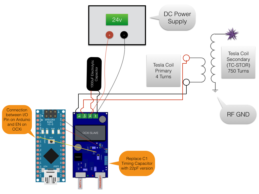
In this example we use an Arduino Nano (programmable circuit) loaded with some code meant to play music on a small speaker. Rather than connecting the output to a speaker, we connect it to the EN connection of the slave OCXi. Doing this causes the Tesla Coil plasma to be modulated at whatever frequency the music is.
 In the videos you can also see a spinning “corona motor”. This is made by simply bending a thin wire into an S shape and making a small loop in the middle so it can be hooked onto a supporting wire. As the plasma forms at the sharp tips of the wire, the air is heated and pushed away giving it some thrust. This will eventually cause the whole wire to spin quite quickly and give this cool looking effect!
This DIY project uses a high voltage system to create a very bright and short burst of light which is ideal for high speed photography. Standard flash guns will illuminate a subject for a relatively long time which will create a blur when photographing high speed events such as bullet impacts or exploding objects.
![]()
WARNING: This project involves large high voltage capacitors. It is very very dangerous! One small mistake could kill instantly. Only experienced high voltage engineers should attempt this project.
By using this homemade high speed flash, it is possible to generate a very short burst of light which is bright enough to allow you to capture high speed events with a typical SLR or DSLR camera.
AVAILABLE PARTS: Below you can find links to buy the key parts for this project
The flash of light comes from the electrical breakdown of ordinary air at atmospheric pressure. When a large enough capacitor is discharged through an air gap, the intense current will briefly generate a burst of electromagnetic radiation covering a wide spectrum. The optical part of this spectrum is seen as a white flash of light just as in lightning discharges.
The circuit uses two high voltage inverters which will convert 12V DC into about 20kV. One inverter is used to charge up a large high voltage capacitor which will be used for discharging energy as a flash of light. The second inverter circuit is used to create a brief high voltage pulse that will trigger the discharge of the main flash on demand.
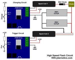 The primary inverter consists of a Power Pulse Width Modulator circuit which is used as an ignition coil driver to power a small High Voltage Spark Coil. The output of the ignition coil is fed through a HV Diode and a small inductor so that it can charge up a bank of large high voltage pulse capacitors. The capacitor terminals are connected to a pair of electrodes that are spaced a little larger than the spark could normally jump when the capacitor is fully charged.
The second inverter circuit is used to briefly ionize the air around the two main electrodes which will allow the capacitor to discharge. Another Power Pulse Width Modulator circuit is set up to drive an ignition coil whenever it is activated by a button or sensor. The output of the ignition coil is directly connected to a wire which is placed near the main electrodes.
When the flash fires, the capacitors may not be fully discharged. It is possible to fit something known as a bleeder resistor between the capacitor terminals. This resistor will slowly discharge the capacitor when not in use. The resistance will have to be very high; something like 100M ohms should be suitable for this.
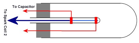 The high speed flash tube consists of two main electrodes on the outside of a small glass tube, plus a third electrode inside the glass tube so that it is isolated from the others.
The main electrodes are made by wrapping some wire around the outside of the tube. The wire used must be thick enough to withstand the high current and heat of the capacitor bank discharge. You could also use something else for the electrodes such as a pair of washers or nuts.
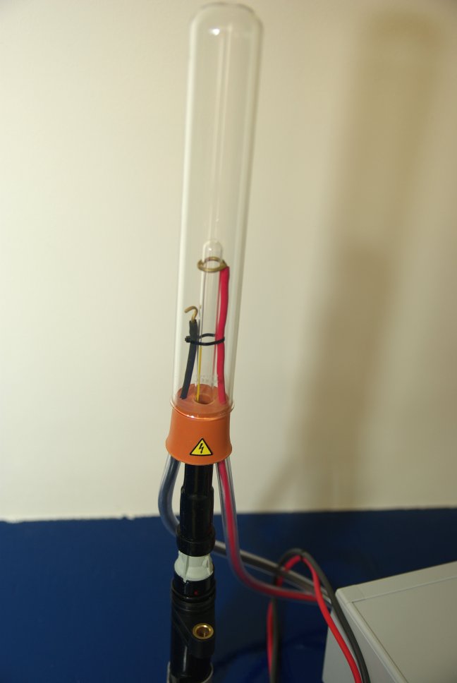
The cables from the electrodes need to be fixed so that they come away from the central tube and do not come close to each other, or anything else. They should be well insulated, especially once they are outside the tube. We used some silicon cable to feed directly from the capacitor to the electrodes and then added extra insulation by feeding the cable through some PVC tubing. This insulation was able to prevent any accidental discharge between the high voltage cables when in use, but should not be considered as safe for handling when live.
The third electrode is a piece of standard solid core wire which is stripped bare at the end. The length of bare wire should be about the length of the gap between the main electrodes. This wire is fitted inside the small glass tube so that the bare section is between the two main electrodes. The other end of the wire leads out of the tube and connects directly to the ignition coil. It can be quite useful to mount the high speed flash tube directly to the end of the HV coil so that it is not necessary to have another large insulated HV cable.
Before building the circuit, it is important to become familiar with the PWM Circuits being used for the ignition coil drivers. The setting of the duty control will determine the charge voltage and rate of charge. Setting this too high will overheat the the circuit or damage components.
The circuit should be powered from a 12V power source capable of delivering at least 3A. Check our notes on power supply considerations as there are tips that can help improve performance. This circuit is a high voltage circuit so the GND connection should be suitably earthed. If using a mains operated supply such as a lab bench PSU, this earth will most likely be built in.
The diagram above shows momentary push to make switches being used to charge and fire the circuit. To charge the flash, the ‘charge’ switch is held down for a few seconds. The exact time need will depend on number of capacitors used and the duty setting of the PWM. There is no built in method to determine if the capacitor bank is charged, so this will come down to user experience with the system. To fire the high speed flash the ‘fire’ switch just needs to be pressed briefly. It is possible to add a sensor instead of a push switch for activating the flash. The sensor just needs to be wired so that will pull low the INT connection of the trigger PWM when the flash needs to fire.
![]()
DANGER: The pressure waves from the discharging flash can cause the glass tubes to break. The tube should also be housed in a sturdy plastic case with reflector to direct the light and to capture any flying glass.
When using the system is is essential to have a clutter free work area, and to prepare for your photographs carefully. This will improve safety and also increase the chances of getting a good picture. The flash tube and capacitors should be fixed securely in position and mounted in such a way that someone could not accidentally touch or get too close to live parts.
To get the high speed photographs with an ordinary camera, the camera shutter needs to stay open so that an image is only exposed when the flash illuminates the subject. Most DSLR cameras will have a ‘bulb’ setting that allows you to keep the shutter open as long as is needed. It is of course essential that when performing DIY high speed photography like this, the room is totally dark (except during the flash) while the camera shutter is open.
The short bright flash from the tube when fired will be very bright and should never be viewed directly. It might also be helpful to wear sunglasses if the subject will be viewed when the flash is activated.
REMEMBER: This project involves high voltage, high current electrical discharges, potentially exploding glass shards, loud bangs, bright flashes, and must be operated in darkness! It is VERY dangerous! This project is here for educational purposes, we do not recommend that you attempt to replicate this project. You are entirely responsible for the way you use the information presented on this website.
The diagram below shows a EHDT in its most basic form. It consists of a fine wire, suspended above a sheet of Aluminium foil, by a lightweight insulating support such as balsa wood. If a high voltage DC source is connected as shown, a thrust will be produced, propelling the device in the direction of the positive wire. This thrust is due the motion of air, or any other dielectric (insulating) fluid around the device, as described below.
![]() WARNING: This project requires the use of dangerous high voltage electricity!
WARNING: This project requires the use of dangerous high voltage electricity!
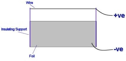
The top sharp electrode ionises the air. If the electrode is positive, free electrons in the vicinity will accelerate towards it, and strip off other electrons from the air molecules around the sharp wire. A cloud of heavy positive charges is thus formed, and the avalanche of electrons approaching the sharp electrode account for the corona & ionisation current.
In their mad rush from the ion emitter to the smooth negative electrode, the positive ions bump into neutral air molecules-air particles without electric charge. The force exerted on them by the electric field is offset by the force of friction caused by collisions of the ions with the neutral air molecules. As a result, ions drift through the air gap with an approximately constant velocity Vd, that is proportional to the electric field given by Vd=kE, where the proportionality constant K is called the ion mobility, the highest the value the more mobile (faster) and the less friction is offered.
 EHDT Construction Details
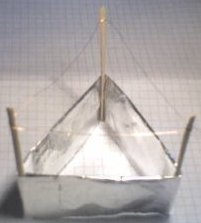
Gently fold over the top a long edge so you are left with a long rounded edge, and a long sharp edge opposite. The rounded edge will be closest to the corona wire.
Fold the strip into three equal sections, plus a little extra for sticking the ends together.
Using a small amount of glue, attach three lightweight balsa wood supports, and stick the two short edges of the foil together to form a triangle.
Loop a thin wire around the supports so that it is a few centimeters from the foil, and leave a long wire for connection to the power supply.
Connect another long wire to the foil, in a position away from the other trailing wire.
The voltage required to power the lifter will depend upon its size but it is usually above 10kV. By moving the top corona wire closer to the foil, more thrust can be produced. If it is too close arcs will jump between the electrodes, causing it not to fly.
Place the thruster on an insulating surface (a table), and away from any metal objects.
Attach the two wires to the table so that the thruster can hover, whilst being held down by the wires.
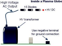
 For a tiny Lifter the output of a plasma globe PSU and a HV diode can be used, but for a larger device a larger transformer may be needed.
The picture on the left is of the inside of the plasma globe, and you can make the output of this DC by connecting it to a HV diode.
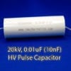
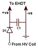
For larger lifters, a simple adjustable supply can be made by driving an high voltage coil with a power pulse modulator and then rectifying the output with a high voltage diode and capacitor as shown here. The diode D1 should be rated for high voltage such as 20kV, 100mA as to withstand current pulses from accidental shorts. The capacitor C1 should also be rated for 20kV. The capacitor is not essential but it can help improve performance and add some protection for the diode. The capacitance can be any value, but bigger is better.
The pulse modulator allows you to vary the output voltage very easily so that you can get more control over the performance of the lifter.
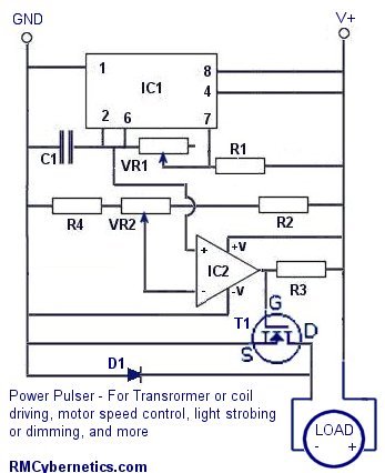
This device uses a built in pulse width modulated signal generator circuit for triggering a power MOSFET.
The circuit is great for controlling the power delivered to a device such as a fan, LED’s or even transformers and coils. By adjusting the pulse width you can easily control the speed of a fan without sacrificing torque.
The transistor used is not critical but generally something with voltage and current ratings suited to your application should be used. We have a range of MOSFETs and IGBTs available. The circuit will run from a 6V – 12V DC supply and the output can be made as ‘open collector’ for higher voltage switching.
Don’t fancy building this DIY PWM Circuit yourself? Check out our range of advanced pulse generators
This circuit diagram shows the load (coil, motor etc) connected to the same supply as the rest of the circuit for simplicity. If you need to switch a higher voltage, the +ve connector of the load can simply be connected to an external supply.
|
Parts List
|
|
| IC1 | LM555 |
| IC2 | LM393 |
| R1 | 10k |
| R2 | 10k |
| R3 | 2.2k |
| R4 | 10k |
| VR1 | 1M |
| VR2 | 10k |
| C1 | 47nF |
| T1 | IRF740 or simlar |
If the circuit is to be used with inductive loads a small capacitor should be connected across the load These are often already fitted on small DC motors. An additional component such as a varistor or ‘freewheel diode’ is also recommended if the pulse generator is driving high voltage flyback transformers like ignition coils.
The two potentiometers VR1 and VR2 are used for controlling the frequency and duty cycle of the output. VR1 adjusts the rate at which C1 is charged for modifying frequency, while VR2 acts as a potential divider allowing a specific voltage to be put on the inverting input of IC2. This voltage is used to control the pulse width of the output. The output duty cycle or pulse width of the device can also be controlled by an external voltage such as a microcontrollers or analog signal. The analog voltage source can simply be connected to the inverting input instead of the output from VR2.
We have a few of these pulse generators designed for use with high voltage transformers which available on the cyber circuits page. These are high quality, ready made on a PCB including a large heatsink and fan, overload protection, and back e.m.f. inductive protection. Theses devices are quite resilient and are ideal for hobbyists and experimenting due to the wide range of potential uses and durability for handling varied loads. If you have random transformers or are making your own coils, these power pulse modulators are ideal for testing and driving them.
Don’t fancy building it yourself? Check out our advanced pulse control circuits. Buy our awesome PWM-OCXI now!
 Using a voltage multiplier is a great way to make a high voltage DC power supply. It is very easy to generate high voltages from easily available components.
This page contains information on where to buy the components and how to connect them. It also gives details of sources of mini high voltage power supplys (inverters) which will run from batteries.
![]() WARNING: Very High Voltage Device!
WARNING: Very High Voltage Device!
 You can see what high voltage static electricity from this device does to a piece of one way window film in the violent discharge experiments section. There are microscope images of the aftermath and a video clip of the explosive action!
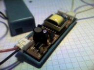
For efficiency a voltage multiplier should be powered from a source that is already a relatively high voltage. There are a variety of small battery operated high voltage power supplys available. Many lighting devices contain inverters for powering vacuum tubes such as, florescent lights, cold cathode lights and plasma globes. These types of devices usually run from 12V DC and can output voltages up to around 20kV AC.
|
Mini cold cathode tube PSU – ~1kV |
Plasma Globe PSU – ~15kV |
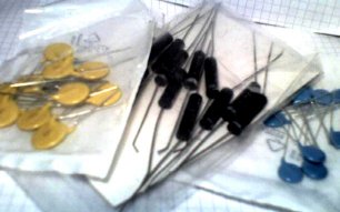 The capacitors and diodes required for the multiplier can be purchased from our shop.
The capacitors and diodes can be arranged in a variety of ways. The half wave method is the easiest as it requires fewer components, but a full wave circuit will perform better. If you just want to get one working as soon as possible the the half wave method would be adequate. The circuit diagrams below indicate how the components should be arranged.
|
Component
|
Max Voltage
|
Source
|
|
1 – 30kV
|
||
|
1 – 30kV
|
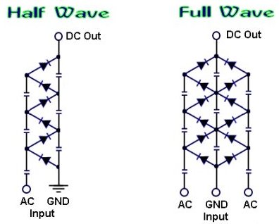
 The schematics above will output a positive DC voltage relative to the ground (GND). If a negative output is required then the polarity of the diodes should be reversed. you can learn more about how a voltage multiplier works, by visiting the voltage multiplier page.
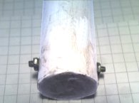
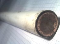
For safety and improved performance the voltage multiplier should be placed in a protective casing, such as a PVC pipe filled with oil. The image on the left shows two protruding screws used for the AC input connection, and he other image shows polished coin used for the high voltage output. By using Polymorph to seal the ends of the pipe, it can be filled with oil to prevent corona leakage from the internal connections. A more sturdy method would be to fill the pipe with epoxy resin, but this may be difficult with compact component arrangement.
 Example Experiments
A homemade voltage multiplier is perfect for powering an EHD thruster (aka Lifter). An EHDT can be made from just aluminium foil, sticks, and fine wire. To learn how , see the ElectroHydroDynamic Thruster page.
Using freezer spray (used by plumbers) you can grow ice crystals on the HV output with interesting results.
For more Simple Experiments with static electricity see the Experiments Section
One of the simplest ways to make a battery powered High Voltage power supply is to use a common car ignition coil. Ignition coils are a type of induction transformer based on the Tesla Coil invented by Nikola Tesla in 1891. The voltage rise is not given by the turns ratio like in a standard transformer, but is proportional to the rate of change of current in the primary circuit. This means to get a high output voltage you must be able to stop the power flowing into the coil as quickly as possible. In old cars this was simply done mechanically. For use as a HV power supply this needs to happen rapidly over and over. To do this a spacial square wave power supply is uses which switches power on and off to the coil hundreds or thousands of times per second.
![]() WARNING: High Voltage is generated by this device!
WARNING: High Voltage is generated by this device!
Standard ignition coils can be obtained from most car parts stores for around £25. It is not essential to use two 12V batteries like shown in the circuits shown below, but it will allow you to obtain bigger sparks. We have some compact induction coils available for sale for under £20. Click the link to check stock.
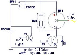
| TR1 | Ignition Coil |
| T1 | BFY51 Small Transistor |
| T2 | 2n3055 Power Transistors or HV MOSFET or IGBT |
| R1 | 100 Ohm Resistor |
| D1 |
1N4007 will do but preferably a Schottky Diode |
| RC1 | 0.1µF Capacitor + 10K Resistor |
This driver circuit is based on the commonly used 2n3055 transistor due to it high power switching capability. While these are cheap and high temperature tolerant, they are susceptible to voltage spikes caused by the inductive nature of the load (ignition coil). Pretty much any power transistor, IGBT or MOSFET can be used in this circuit as long as it is rated for at last 5A and 100V. Ones with higher voltage ratings will be less likely to be damaged by spikes. Further protection methods are outlined lower down this page and in the comments. If you use a MOSFET or IGBT instead of a bipolar transistor like the 2n3055, you should also add a pulldown resistor of about 10k between the base/gate pin and GND.
RC1 is used to help suppress high voltage spikes that can destroy the power transistors.
T2 represents two power transistors connected in parallel and mounted on a heatsink.
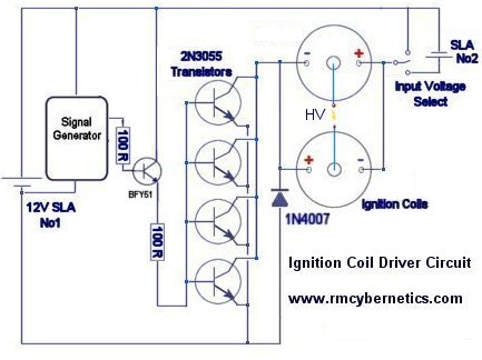 This next circuit is designed for a higher powered output. Two ignition Coils are connected in parallel but with opposite polarity. This means that the output voltages of each coil are out of phase or opposite to each other (when one is positive, the other is negative). Using this configuration the output is taken from the two coils output terminals, whereas the circuit above uses the output terminal and ground.
These circuits will work great for driving ignition coils for high voltage but they can be susceptible to damage from inductive spikes. When an ignition coil is being driven unloaded (open circuit on the output) there will be significantly increased back emf and risk of damaging the driver circuit. We sell an ignition coil driver module which has built in protection against most spikes that would damage a driver. It also includes an early warning indicator which will show you how severe the back emf is from your load.
 If you build an ignition coil driver to make high voltage sparks and arcs, you will need some sort of EMI protection for your circuit. Without it, it is very likely you will destroy the transistors or driver ICs.
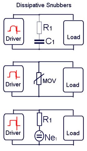
Snubbers are a tricky subject, but in general they are used to reduce electromagnetic interference (EMI) or voltage spikes. There are many ways to reduce EMI and it can often be useful to use various snubbers in different parts of the circuit. These diagrams represent a few possible ways you can snub EMI in an ignition coil driver. These are known as dissipative snubbers because the excess energy is disspated as heat or light.
The top digram uses a series connected capacitor and resistor. The values used will depend on your drive frequency. (See RC1 at top of this page). Generally speaking, a bigger capacitance and smaller resistance will snub more, but also absorb more drive power thefore reducing efficiency. A compromise must be found that best suits your setup.
The next diagram uses a device known as a MOV (Metal Oxide Varistor). These are semiconductor devices which will only begin conducting when the voltage between its terminals exceeds its rated value. It will stop conducting when the voltage goes low again. In the example shown above, the MOV will short out any spikes coming from the load, but it is also shorting the driver circuits output for the same brief instant. The MOV chosen must be able to dissipate the power ans have a voltage rating that will cause it to activate before the voltage gets too high for the drive circuit.
You can also place a small neon indicator bulb (Ne1)in series with a 1k resistor and place this between the low voltage wires to your ignition coil. This bulb will begin to glow when the back EMF reaches about 100V or more. If you see it glowing, you need a better snubber like RC1 (top diagram) or a MOV (varistor) rated to clamp the voltage below the maximum your components will tolerate.
 Solid State Relay 40A
$17.19
Solid State Relay 40A
$17.19
 HV Spark Coil
$37.04
HV Spark Coil
$37.04
 Power Pulse Modulator - PWM-OCXi v3
$144.89
Power Pulse Modulator - PWM-OCXi v3
$144.89
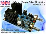
 Power Pulse Modulator - PWM-OCX v2.2
$128.03
Power Pulse Modulator - PWM-OCX v2.2
$128.03
 Polypropylene Capacitor 400V 330nF
$3.30
Polypropylene Capacitor 400V 330nF
$3.30