DIY Plasma Gun

A Hand Held Tesla Coil Battery Powered ‘Plasma Gun’
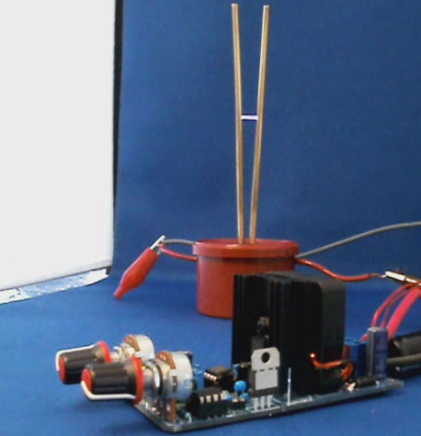
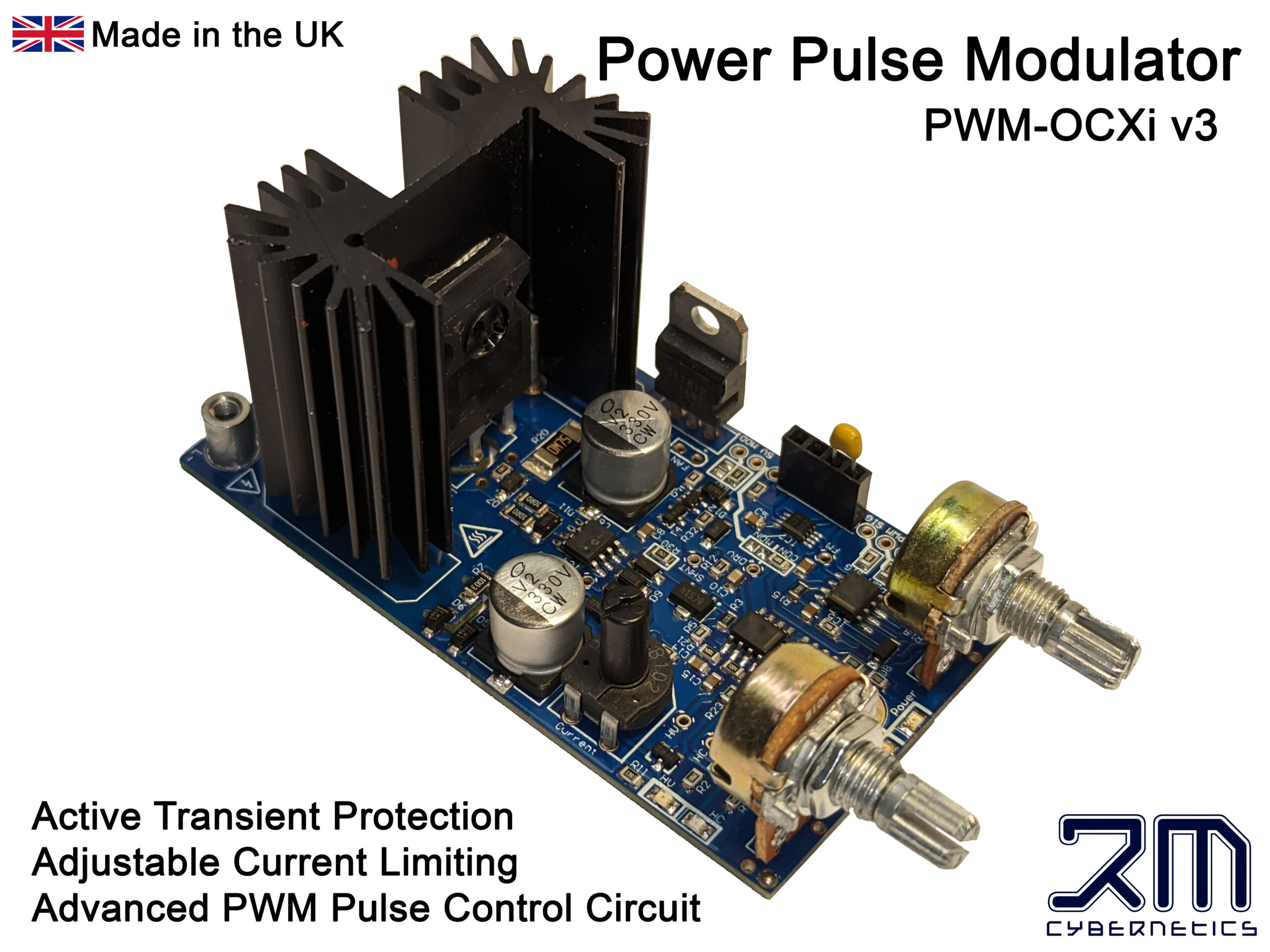
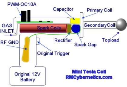
The design for this Tesla Coil is based on the larger battery powered DIY Tesla Coil project but with the aim of getting a much smaller and portable device. A Power Pulse Modulator circuit is used to drive two small high voltage ignition coils wired together in an ‘anti-parralel’ configuration. The output is rectified and used to charge the tank capacitor of a small spark gap Tesla Coil.
| WARNING: This project uses dangerous high voltages! |
| This project is quite old now. Check out the new, more powerful DIY Plasma Gun! |
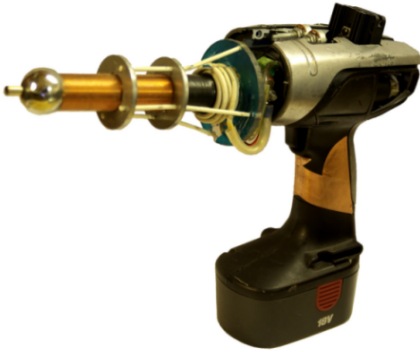
The device is packed into the casing of cheapo cordless drill from a DIY store. This drill used an 18V battery and comes with a charger which made it ideal for the project. The ignition coil driver circuit used takes a direct 12V – 30V input which is connected using the original switch from the drill.
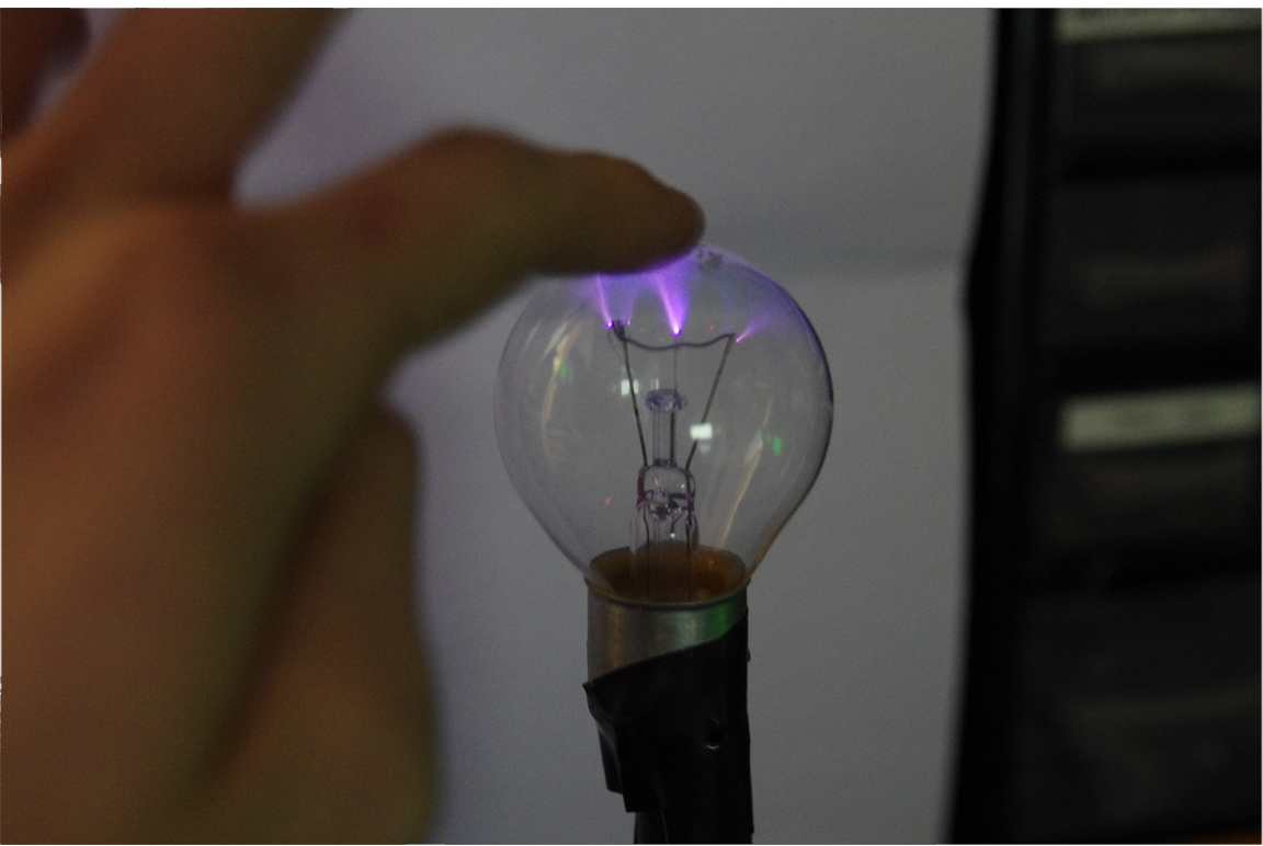
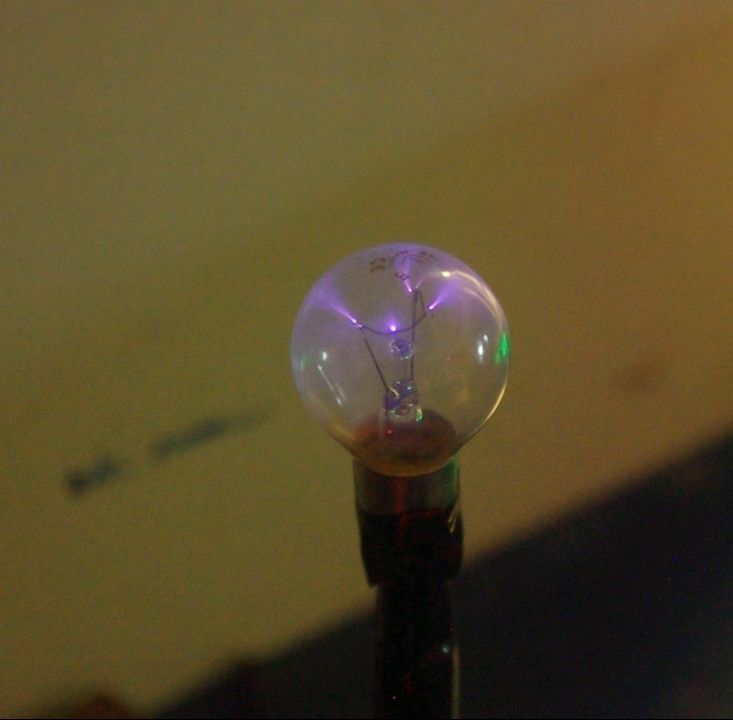
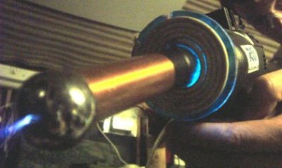
This video clip shows the plasma gun causing a nearby light bulb to light up as if it were a plasma globe.
The high frequency, high voltage from the plasma gun causes the Argon gas in the light bulb to become ionized. This creates streamers that are attracted to the fingers holding it.
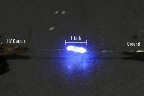
The device draws about 6 amps from a well charged 12 V battery which makes the total power consumption to around 72 watts. Unfortunately this low power means the plasma arcs will be limited in size, but since it is hand held that’s probably a good thing. The typical length of the output arcs is between 5 and 7cm

Such a small Tesla Coil inherently has quite a high resonant frequency which in this case is about 500 kHz. This frequency is too high to feel as electric shock but when being zapped you can feel the low frequency component of the spark gap firing rate.
| PARTS LIST | |
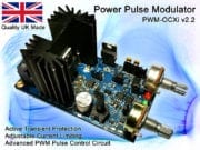
| PWM-OCXi | Drive Circuit |
| SW1 | Trigger Switch |
| Spark Coil 1 & 2 | Small Ignition Coils |
| D1 | 20kV Diode x 4 |
| C1 | 1nF 15kV |
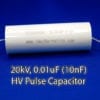
| C2 | 2nF 15kV |
| C3 | Topload Sphere |
| L1 | RF Choke 10uH |
| L2 | RF Choke 10uH |
| L3 | TC Primary Coil |
| L4 | TC Secondary Coil |
| Input Voltage | 12V DC |
| Power Consumption | 75W Max |
| Max Arc Length | 5cm (in air) |
| 7cm (in gas) | |
| Output Voltage (approx) | 50kV |
| Primary Transformer | 2 x small ignition coils < 20kV |
| Spark Gap | Sealed Static Gap. ~4mm |
| Primary Turns | 5 |
| Primary Diameter | 70mm |
| Primary Inductance | 1uH |
| Secondary Turns | 520 |
| Secondary Height | 135mm |
| Secondary Diameter | 26mm |
| Secondary Inductance | 900uH |
| Secondary Resistance | 10 ohms |
| Topload | 32mm Sphere |
| Special Features | Hand Held |
| Portable | |
| Battery Powered | |
| Trigger Activated | |
| Plasma/Flame discharge | |
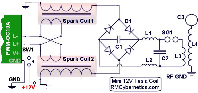
The main driving circuit is a type of pulse width modulation circuit with protection against high voltage spikes. It is adjusted to get the maximum output from the two ignition coils.
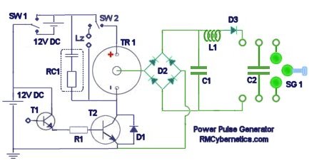
The two ignition coils were stripped of the casing in order to reduce the overall size and allow access to the internal wiring. The inputs are wired in an anti-parallel arrangement to help keep the charging voltage high when under load.
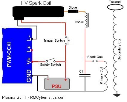
The HV outputs of the spark coils are connected to a rectifier (D1) made from four HV diodes potted in epoxy resin. Connected to this is a small smoothing capacitor (C1) which helps to reduce the ripple in the HV DC output. The tank capacitor (C2) is charged from the HV DC supply via two RF chokes (inductors L1 & L2) which serve to prevent the RF oscillations of the TC primary circuit from interfering with the rest of the circuit.
The previous battery powered tesla coil design needed to be well connected to a good RF ground such as a metal rod in the earth. Without this the output would be limited and the driver circuit would be prone to failure.
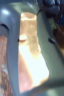 With this mini tesla coil the RF ground connection is made by connecting it to a copper pad on the handle.
The body of the person holding the device is used as the RF ground and the large area of copper ensures the energy is spread out to prevent RF burns.
In most Tesla Coils this would not be safe at all but this device is very low power so there is little risk of electric shock. The RF its self probably isn’t too healthy though!
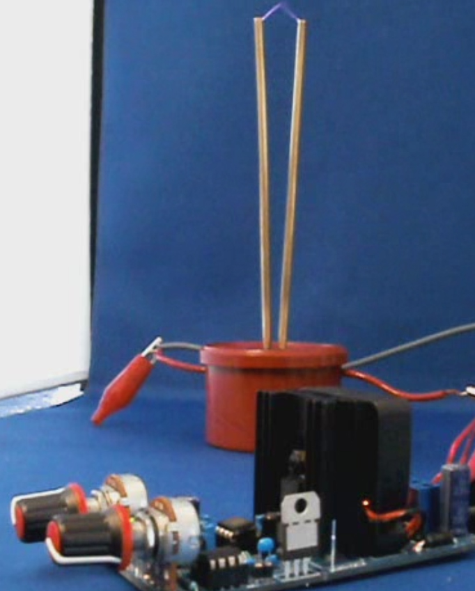
The TC part (Tesla Coil) uses the common single static spark gap and flat primary design for simplicity and size. The primary coil is closely wound around the base of the secondary with several layers of insulation tape preventing flashover.
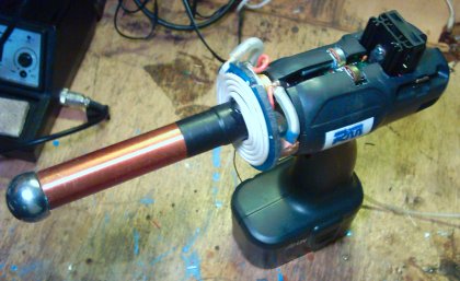
The topload sphere is made from a metal draw handle which has been drilled to allow gas to be ejected from the end. A pipe from this sphere runs down the inside of the secondary and to the back of the handle where it can be connected to a gas supply.
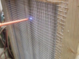
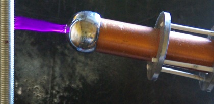
Using noble gasses such as Argon or Neon will cause the output arcs to be forced along the flow of gas. This allows the plasma to be directed in a straight line from the tip of the plasma gun. It is also possible to use butane gas which makes this thing into some kind of flamethrower – plasma gun hybrid. The electricity is conducted along the flame from its tip. You can see photos of this effect on our plasma page.
 Apart from making cool arcs of plasma, this device even transmits wireless electrical power. It can light bulbs and fluorescent lights just from being nearby.
The interference created by this wireless energy can cause all sorts of electronic devices to switch on and off or start behaving erratically. This is because the energy is causing tiny currents to be induced in the tracks and wires in the devices. If a simple circuit had a matching resonant frequency to that of the plasma gun, it would be possible to collect the wireless energy from a greater distance.
 There are several improvements that could be made on this design which could result in a greater power throughput and therefore bigger arcs.
The spark gap is just a single gap which has been seal inside a plastic case for safety and size. This sort of switching will have poor performance due to quenching difficulties and oxide buildup. A solid state version would be better but it would likely be larger and considerably more expensive.
A larger topload would allow for larger breakouts, but it would also need more primary capacitance. The secondary coil is also rather long relative to its width. Ideally this would be shorter and wider.
In conclusion this was a fun project and we hope you find this information useful and interesting.
 A Multi-purpose power pulse generator capable of driving Tesla Coils and other high power coils. This device is based on the

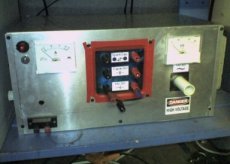
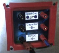 The main high voltage front panel on the box has sockets for HV DC output, an internal HV pulse discharge capacitor, and an internal spark gap. This allows the high voltage circuits to be configured in a number of different ways without having to re-wire any internal components.
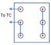 The image on the right shows how the panel is wired to drive a Tesla Coil. The spark gap can be adjusted using a handle on the side of the case. Depending upon the resonant frequency of the TC being driven, it may be necessary to adjust the capacitance. This can simply be done by adding more capacitors in parallel, or using a separate one.
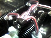 This image shows the interconnected outputs of the ignition coils. The ignition coils are wired in parallel to give a higher output current.
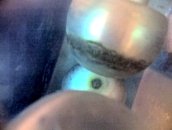 This new spark gap is made using three spherical electrodes in a high K dielectric casing. The double casing of the spark gap reduces the overall noise and allows the airflow to be doped with other gasses.The anode and cathode are spaced further than the voltage could jump and the third sphere can be moved in and out of the gap via a long glass fibre rod. This allows the spark gap to be adjusted smoothly anywhere between short and open circuit whilst it is active.
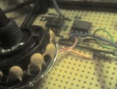 The control circuit used for generating the driving signal is made using a 555 based circuit. This circuit can be found on the DIY Devices Page and is titled
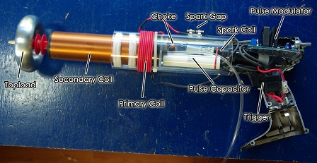
 The power to the ignition coil was fed directly from the drill battery via the original trigger switch, into the L- connector on the OCXI. By connecting like this, the control circuit and its cooling fan stays active between times when the plasma gun is fired.