-
×
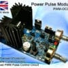
 Power Pulse Modulator - PWM-OCmi (HV)
1 × $52.91
Power Pulse Modulator - PWM-OCmi (HV)
1 × $52.91
Subtotal: $52.91
Power Pulse Modulator - PWM-OCmi (HV)
1 × $52.91 Subtotal: $52.91
This section gives details of many DIY science projects and equipment which can be made at home.
One of the simplest ways to make a battery powered High Voltage power supply is to use a common car ignition coil. Ignition coils are a type of induction transformer based on the Tesla Coil invented by Nikola Tesla in 1891. The voltage rise is not given by the turns ratio like in a standard transformer, but is proportional to the rate of change of current in the primary circuit. This means to get a high output voltage you must be able to stop the power flowing into the coil as quickly as possible. In old cars this was simply done mechanically. For use as a HV power supply this needs to happen rapidly over and over. To do this a spacial square wave power supply is uses which switches power on and off to the coil hundreds or thousands of times per second.
![]() WARNING: High Voltage is generated by this device!
WARNING: High Voltage is generated by this device!
Standard ignition coils can be obtained from most car parts stores for around £25. It is not essential to use two 12V batteries like shown in the circuits shown below, but it will allow you to obtain bigger sparks. We have some compact induction coils available for sale for under £20. Click the link to check stock.
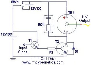
| TR1 | Ignition Coil |
| T1 | BFY51 Small Transistor |
| T2 | 2n3055 Power Transistors or HV MOSFET or IGBT |
| R1 | 100 Ohm Resistor |
| D1 |
1N4007 will do but preferably a Schottky Diode |
| RC1 | 0.1µF Capacitor + 10K Resistor |
This driver circuit is based on the commonly used 2n3055 transistor due to it high power switching capability. While these are cheap and high temperature tolerant, they are susceptible to voltage spikes caused by the inductive nature of the load (ignition coil). Pretty much any power transistor, IGBT or MOSFET can be used in this circuit as long as it is rated for at last 5A and 100V. Ones with higher voltage ratings will be less likely to be damaged by spikes. Further protection methods are outlined lower down this page and in the comments. If you use a MOSFET or IGBT instead of a bipolar transistor like the 2n3055, you should also add a pulldown resistor of about 10k between the base/gate pin and GND.
RC1 is used to help suppress high voltage spikes that can destroy the power transistors.
T2 represents two power transistors connected in parallel and mounted on a heatsink.
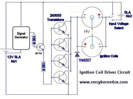 This next circuit is designed for a higher powered output. Two ignition Coils are connected in parallel but with opposite polarity. This means that the output voltages of each coil are out of phase or opposite to each other (when one is positive, the other is negative). Using this configuration the output is taken from the two coils output terminals, whereas the circuit above uses the output terminal and ground.
These circuits will work great for driving ignition coils for high voltage but they can be susceptible to damage from inductive spikes. When an ignition coil is being driven unloaded (open circuit on the output) there will be significantly increased back emf and risk of damaging the driver circuit. We sell an ignition coil driver module which has built in protection against most spikes that would damage a driver. It also includes an early warning indicator which will show you how severe the back emf is from your load.
 If you build an ignition coil driver to make high voltage sparks and arcs, you will need some sort of EMI protection for your circuit. Without it, it is very likely you will destroy the transistors or driver ICs.
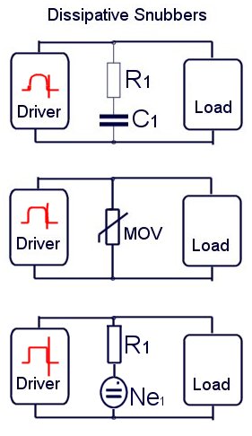
Snubbers are a tricky subject, but in general they are used to reduce electromagnetic interference (EMI) or voltage spikes. There are many ways to reduce EMI and it can often be useful to use various snubbers in different parts of the circuit. These diagrams represent a few possible ways you can snub EMI in an ignition coil driver. These are known as dissipative snubbers because the excess energy is disspated as heat or light.
The top digram uses a series connected capacitor and resistor. The values used will depend on your drive frequency. (See RC1 at top of this page). Generally speaking, a bigger capacitance and smaller resistance will snub more, but also absorb more drive power thefore reducing efficiency. A compromise must be found that best suits your setup.
The next diagram uses a device known as a MOV (Metal Oxide Varistor). These are semiconductor devices which will only begin conducting when the voltage between its terminals exceeds its rated value. It will stop conducting when the voltage goes low again. In the example shown above, the MOV will short out any spikes coming from the load, but it is also shorting the driver circuits output for the same brief instant. The MOV chosen must be able to dissipate the power ans have a voltage rating that will cause it to activate before the voltage gets too high for the drive circuit.
You can also place a small neon indicator bulb (Ne1)in series with a 1k resistor and place this between the low voltage wires to your ignition coil. This bulb will begin to glow when the back EMF reaches about 100V or more. If you see it glowing, you need a better snubber like RC1 (top diagram) or a MOV (varistor) rated to clamp the voltage below the maximum your components will tolerate.

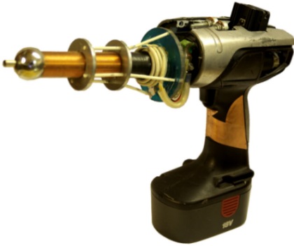
A Hand Held Tesla Coil Battery Powered ‘Plasma Gun’
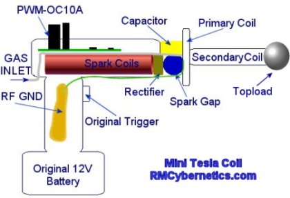
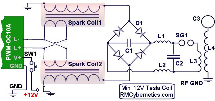
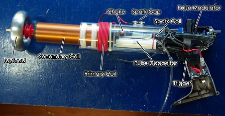
The design for this Tesla Coil is based on the larger battery powered DIY Tesla Coil project but with the aim of getting a much smaller and portable device. A Power Pulse Modulator circuit is used to drive two small high voltage ignition coils wired together in an ‘anti-parralel’ configuration. The output is rectified and used to charge the tank capacitor of a small spark gap Tesla Coil.
| WARNING: This project uses dangerous high voltages! |
| This project is quite old now. Check out the new, more powerful DIY Plasma Gun! |
The device is packed into the casing of cheapo cordless drill from a DIY store. This drill used an 18V battery and comes with a charger which made it ideal for the project. The ignition coil driver circuit used takes a direct 12V – 30V input which is connected using the original switch from the drill.
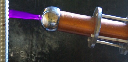
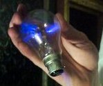
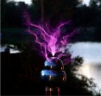
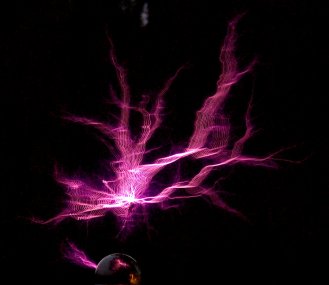
This video clip shows the plasma gun causing a nearby light bulb to light up as if it were a plasma globe.
The high frequency, high voltage from the plasma gun causes the Argon gas in the light bulb to become ionized. This creates streamers that are attracted to the fingers holding it.
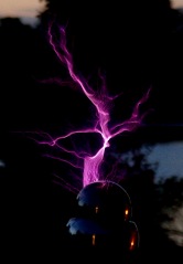
The device draws about 6 amps from a well charged 12 V battery which makes the total power consumption to around 72 watts. Unfortunately this low power means the plasma arcs will be limited in size, but since it is hand held that’s probably a good thing. The typical length of the output arcs is between 5 and 7cm
Such a small Tesla Coil inherently has quite a high resonant frequency which in this case is about 500 kHz. This frequency is too high to feel as electric shock but when being zapped you can feel the low frequency component of the spark gap firing rate.
| PARTS LIST | |
| PWM-OCXi | Drive Circuit |
| SW1 | Trigger Switch |
| Spark Coil 1 & 2 | Small Ignition Coils |
| D1 | 20kV Diode x 4 |
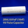
| C1 | 1nF 15kV |
| C2 | 2nF 15kV |
| C3 | Topload Sphere |
| L1 | RF Choke 10uH |
| L2 | RF Choke 10uH |
| L3 | TC Primary Coil |
| L4 | TC Secondary Coil |
| Input Voltage | 12V DC |
| Power Consumption | 75W Max |
| Max Arc Length | 5cm (in air) |
| 7cm (in gas) | |
| Output Voltage (approx) | 50kV |
| Primary Transformer | 2 x small ignition coils < 20kV |
| Spark Gap | Sealed Static Gap. ~4mm |
| Primary Turns | 5 |
| Primary Diameter | 70mm |
| Primary Inductance | 1uH |
| Secondary Turns | 520 |
| Secondary Height | 135mm |
| Secondary Diameter | 26mm |
| Secondary Inductance | 900uH |
| Secondary Resistance | 10 ohms |
| Topload | 32mm Sphere |
| Special Features | Hand Held |
| Portable | |
| Battery Powered | |
| Trigger Activated | |
| Plasma/Flame discharge | |
The main driving circuit is a type of pulse width modulation circuit with protection against high voltage spikes. It is adjusted to get the maximum output from the two ignition coils.
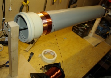
The two ignition coils were stripped of the casing in order to reduce the overall size and allow access to the internal wiring. The inputs are wired in an anti-parallel arrangement to help keep the charging voltage high when under load.
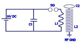
The HV outputs of the spark coils are connected to a rectifier (D1) made from four HV diodes potted in epoxy resin. Connected to this is a small smoothing capacitor (C1) which helps to reduce the ripple in the HV DC output. The tank capacitor (C2) is charged from the HV DC supply via two RF chokes (inductors L1 & L2) which serve to prevent the RF oscillations of the TC primary circuit from interfering with the rest of the circuit.
The previous battery powered tesla coil design needed to be well connected to a good RF ground such as a metal rod in the earth. Without this the output would be limited and the driver circuit would be prone to failure.
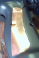 With this mini tesla coil the RF ground connection is made by connecting it to a copper pad on the handle.
The body of the person holding the device is used as the RF ground and the large area of copper ensures the energy is spread out to prevent RF burns.
In most Tesla Coils this would not be safe at all but this device is very low power so there is little risk of electric shock. The RF its self probably isn’t too healthy though!
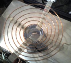
The TC part (Tesla Coil) uses the common single static spark gap and flat primary design for simplicity and size. The primary coil is closely wound around the base of the secondary with several layers of insulation tape preventing flashover.
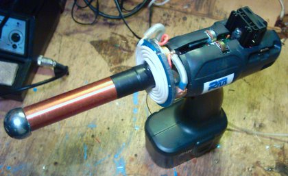
The topload sphere is made from a metal draw handle which has been drilled to allow gas to be ejected from the end. A pipe from this sphere runs down the inside of the secondary and to the back of the handle where it can be connected to a gas supply.
Using noble gasses such as Argon or Neon will cause the output arcs to be forced along the flow of gas. This allows the plasma to be directed in a straight line from the tip of the plasma gun. It is also possible to use butane gas which makes this thing into some kind of flamethrower – plasma gun hybrid. The electricity is conducted along the flame from its tip. You can see photos of this effect on our plasma page.
 Apart from making cool arcs of plasma, this device even transmits wireless electrical power. It can light bulbs and fluorescent lights just from being nearby.
The interference created by this wireless energy can cause all sorts of electronic devices to switch on and off or start behaving erratically. This is because the energy is causing tiny currents to be induced in the tracks and wires in the devices. If a simple circuit had a matching resonant frequency to that of the plasma gun, it would be possible to collect the wireless energy from a greater distance.
 There are several improvements that could be made on this design which could result in a greater power throughput and therefore bigger arcs.
The spark gap is just a single gap which has been seal inside a plastic case for safety and size. This sort of switching will have poor performance due to quenching difficulties and oxide buildup. A solid state version would be better but it would likely be larger and considerably more expensive.
A larger topload would allow for larger breakouts, but it would also need more primary capacitance. The secondary coil is also rather long relative to its width. Ideally this would be shorter and wider.
In conclusion this was a fun project and we hope you find this information useful and interesting.
 A Multi-purpose power pulse generator capable of driving Tesla Coils and other high power coils. This device is based on the Homemade Tesla Coil project and uses an improved version of the ignition coil driver circuit to generate high voltages.
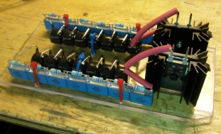
This unit quite simply can generate high current pulses of variable frequency and pulse width. This unit uses the Square wave frequency generator shown in the DIY Devices section for the main signal source but any other signal source can also be connected to it. The input signal is amplified using an array of nine 2N3055 power transistors (T2) which is capable of switching huge amounts of power.
| WARNING: High Voltage is used in this project! |
A switch allows power to be sent to external coils for low voltage applications, or the internal ignition coils can be powered for charging a large HV pulse discharge capacitor.
The low voltage circuit in this device is similar to the driver for the Homemade Tesla Coil, but with some important differences. The high current pulses from the Lead Acid Batteries makes the signal generator unstable in the original design. The new version uses a completely independent signal source with its own battery to minimize the interference. There is also an extra buffer circuit to protect the 2N3055 Transistors from voltage spikes caused by the inductive kickback from the auto ignition coils.
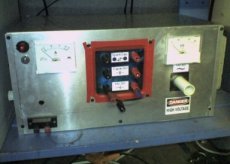
All the power electronics are housed in an Aluminum case finished with panel meters, IO ports, and switches. The signal generator circuit is housed in an independent unit with its own 9V battery. This can be connected to the main unit via a shielded cable allowing it to be operated from a safe distance.
The high voltage output from the ignition coils is rectified using some large high voltage diodes (D2) designed for X-Ray machines. The rectified output is connected to a large capacitor (C1) for smoothing the DC output. From the smoothing capacitor an inductor (L1) and an additional ‘de-Q-ing’ diode (D3) have been added to the charging circuit to block the AC ringing from the TC primary coil from reaching the the smoothing capacitor. These also help to protect the the rectifier from short circuits, arcing currents and possible back EMF or transients.
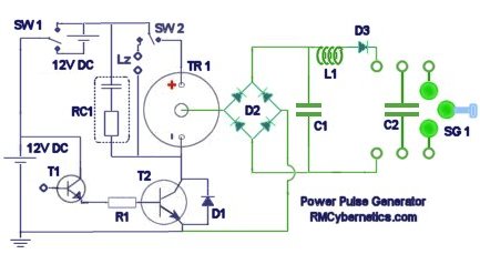
| SW1 | Low Voltage Selection Switch |
| SW2 | Lz |
| TR1 | Four Ignition Coils in Parallel |
| RC1 | Spike Filter |
| T1 | BFY 51 Transistor (Preamplifier) |
| T2 | 2n3055 (nine in parallel) |
| D1 | High Power Diode |
| D2 | High Voltage Rectifier |
| D3 | ‘de-Q-ing’ Diode |
| C1 | High Voltage Smoothing Capacitor |
| C2 | Pulse Discharge Tank Capacitor |
| L1 | Homemade Inductor |
| SG1 | Variable Spark Gap |
| The connectors used here are just standard banana types. They are not designed for high voltage use and will therefore leak a little energy by ionising the air nearby. |
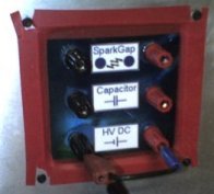 The main high voltage front panel on the box has sockets for HV DC output, an internal HV pulse discharge capacitor, and an internal spark gap. This allows the high voltage circuits to be configured in a number of different ways without having to re-wire any internal components.
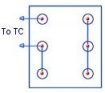 The image on the right shows how the panel is wired to drive a Tesla Coil. The spark gap can be adjusted using a handle on the side of the case. Depending upon the resonant frequency of the TC being driven, it may be necessary to adjust the capacitance. This can simply be done by adding more capacitors in parallel, or using a separate one.
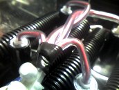 This image shows the interconnected outputs of the ignition coils. The ignition coils are wired in parallel to give a higher output current.
All the high voltage cabling inside the box is placed inside flexible plastic tubing for added insulation. You can see here that the low voltage connections to the ignition coils are also covered with tubing for added protection.
The case is grounded by connecting a thick wire to a long metal spike driven into the ground. All of the ground connections for the internal circuits are also connected to the case.
Connecting the case to the earth spike is essential when using the device to drive Tesla coils. This is because a Tesla Coil (TC) will generate radio frequency (RF) currents that would otherwise become present throughout the circuit. Without a good RF ground you would probably receive little shocks from the controls when operating a Tesla Coil.
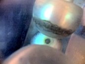 This new spark gap is made using three spherical electrodes in a high K dielectric casing. The double casing of the spark gap reduces the overall noise and allows the airflow to be doped with other gasses.The anode and cathode are spaced further than the voltage could jump and the third sphere can be moved in and out of the gap via a long glass fibre rod. This allows the spark gap to be adjusted smoothly anywhere between short and open circuit whilst it is active.
A pair of 12V DC brushless fans are installed to improve airflow through the spark gap. This is not to improve quenching, but it will reduce electrode corrosion from Ozone buildup in the spark gap casing. A further filtering capacitor has been added across the fans connectors as this type is sensitive to voltage spikes
 The control circuit used for generating the driving signal is made using a 555 based circuit. This circuit can be found on the DIY Devices Page and is titled Signal Generator with Pulse Width Control. This circuit is housed inside a small hand held box with a 9V battery. It can be connected to the Power Pulse Generator by a jack plug on the end of the cable from the unit. You can buy an advanced version of this signal source here.
Different ignition coils or transformers will have different resonant frequencies. Using this circuit allows the Ignition coils to be tuned and driven at their resonant frequency.
External transformers, coils, or solenoids can also be driven at any desired frequency within the range of the 555 timer. The pulse width modulation capabilities of the control circuit are used for power level control for transformers and other coils. This feature also allows large or small DC motors to be powered with variable speed between 0% and 100%. These can also be tuned to their resonant frequency.
This device is capable of powering a multitude of experiments and is great for any researcher experimenting with pulsed power or resonant applications. You can see experiments we have done with Tesla Coils using this device on the Tesla Coil Experiments page.
The DIY Plasma Gun II is an improved version of a compact, portable, spark gap Tesla coil which can create jets of high voltage plasma and even doubles as a flame thrower! This updated version of our hand held Tesla Coil has been optimized for improved efficiency and gives a larger output than the previous one. It is also now even easier to build! You can find the old version on the original Plasma Gun page. We decided to stick to a spark gap type Tesla Coil for this plasma gun as it is considerably easier to build and more reliable than solid state controllers. We will however produce a solid state version in future.
This page should show you all you need to know about how to make a plasma gun like the one shown here. Hopefully it will also teach you the science behind it so that you will know how it works. Remember that this is a dangerous high voltage project and should not be attempted by inexperienced people.
This plasma gun is essentially a small battery powered spark gap Tesla coil. Its inteded purpous is more for education, than an actual function. We hope that is is a fun and interesting project and that you will learn something from it. If you make your own plasma gun, please post a picture below!
The plasma is made by ionizing air around the output terminal of the Tesla coil. The high frequency, high voltage electricity is able to form streams of plasma that can be made to spread out, or be directed forward along a flame or stream of gas. This directed plasma channel can actually have a useful function in some industrial processes known as “plasma surface treatment”. When the jet of plasma is directed at a surface such as a plastic bottle, subtle changes will occur in the structure of the material on a very thin surface layer. Typically these changes will make the surface more porous, or easier to print onto.
Anyway, enough of that, we know you really want it just becasue it’s cool, and you want to build your own plasma gun! On to how it’s made…
![]() Warning: This project involves dangerous high voltage electricity!
Warning: This project involves dangerous high voltage electricity!
High Voltage Inverter
For converting the low battery voltage into high voltage for charging the primary capacitor.
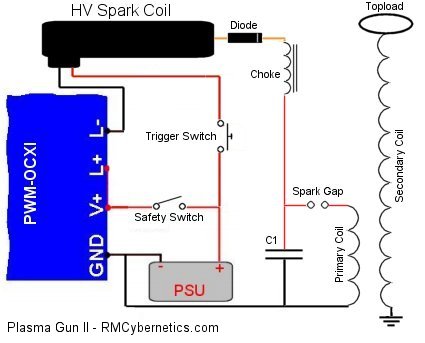
This part of the plasma gun does the main power conversion by pulsing a high voltage ignition coil. Pulsing the spark coil will step up the voltage from the battery to about 20kV which is used to charge the main capacitor. This capacitor is later discharged into the primary coil of a Tesla Coil to further increase the voltage.
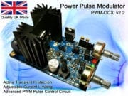
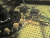
For this we used a Power Pulse Modulator (PWM-OCXI) as it is really simple to use and will give a really powerful high voltage output from an ignition coil. The PWM-OCXI is considerably more powerful than the PWM-OC10A which was used in the original plasma gun project and therefore improves power throughput significantly. This circuit was mounted in the back end of a cordless drill casing so that the control pots and LEDs were accesable from the back. At the side of the drill casing a small switch was mounted that could be used to switch the circuit on and off. This serves as a safety to power down the plasma gun when not in use.
 The power to the ignition coil was fed directly from the drill battery via the original trigger switch, into the L- connector on the OCXI. By connecting like this, the control circuit and its cooling fan stays active between times when the plasma gun is fired.
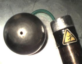
It is neccesary to add a high voltage diode to the output of the ignition coil so that a capacitor can be charged. For this, the rubber end of the ignition coil was removed, and the diode connected to the spring inside the tip. The tip was then filled with epoxy resin so that the high voltage would not flash over the body of the diode. This also helps to cool the diode by absorbing heat from it. The cathode wire is left protruding from the resin so that it can be connected to a small inductor. This inductor serves as a choke to protect the diode from the high frequency currents in the primary circuit.
Primary Tank Circuit
For storing energy in a resonant circuit to be rapidly discharged in pulses.
The primary tank circuit here consists of a high voltage capacitor, spark gap, and a coil of wire (an inductor) known as the primary coil. When the capacitor becomes charged to a high enough voltage, the air between the terminals of the spark gap will break down with a loud bang and a bright flash. During this very brief flash, the energy in the capacitor will be moved into the primary coil and then back again over and over at about 1,000,000 times per second! This frequency of 1MHz is determined by the sizes of the capacitor and the coil and is know as the resonant frequency. The resonant frequency of this inductor capacitor combination can be calculated as follows;
Primary Circuit Resonant Frequency
f = 1 / (2 x π x √(L x C)) = 1,000,000 Hertz
Where f = Resonant frequency, L = Inductance and C = Capacitance
The value of the capacitor is fixed, and the inductance of the primary coil is determined by its size and the number of turns of wire used to make it.
The capacitor used was chosen for improved efficiency over the ceramic capacitors used in the original Plasma Gun. By using a quality polypropelene capacitor with a low ESR and low ESL, the losses in the high frequency resonant circuit are reduced significantly. This means more awesome sparks!
When choosing the values for the components a number of factors must be considered. Some factors are fixed, while others can be varied. The table below details some of the points which must be considered.
| Parameter | Notes |
| Physical Size | The physical size was chosen to be limited to something that can be held in the hand like a gun. This size limit means that the secondary coil of the Tesla Coil must either have relatively few turns, or must use very thin wire so that more turns can fit on the form. The power supply will be limited due to size, so it is important to choose a powerful battery. |
| Secondary Coil | The design of this coil determines the resonant frequency of the diy plasma gun and therefore will limit your options for other parts in the circuit. Thin wire would cause losses due to resistance, while thicker wire will mean less turns and therefore a higher resonant frequency. |
| Resonant Frequency | The size constraint means that the resonant frequency will be relatively high. Such high frequency will cause more losses and increased impedance. It also means that a large primary voltage is needed to get a good current to flow in the primary circuit. |
| Primary Circuit | The primary circuit needs to be adjustable so that it can be tuned to match the secondary coil’s resonant frequency. Without proper tuning the plasma gun will not give a good output spark. |
Secondary Coil
Self resonant circuit which magnifies the primary voltage so that it can discharge as plasma streams.
By using 0.25mm wire there is a reasonable amount of copper for conducting current through the coil but due to the small size, only 750 can be fit onto the coil. Without a discharge terminal (topload), the resonant frequency is around 1100kHz. Such a high frequency introduces losses so we can reduce this frequency by adding a larger topload. The toroid used brings it down to a more reasonable 900kHz.
Due to the high electrical stresses, it is important to insulate the coil well with multiple layers of varnish. Although this introduces more dielectric losses, it is essential for preventing sparks flashing over the surface of the coil and for protecting the windings.
Breakout Electrode
For concentrating the electrical discharge in a focused place.
By using a large topload, the electrical field is spread over a large area and will not break out in to arcs until the voltage is very high. While this is advantageous for increasing arc length, it also increases the chances of the arc discharging back towards the coils. The breakout point creates a localised area of intense electric field which will ionise the air more easily and force the discharge away from the end of the plasma gun.
The electrode is fitted with a pipe so that gas can be ejected from the the tip. Some gasses such as Argon or Carbon Dioxide will ionise more easily than air. When ionised it will provide a conductive path, allowing the plasma to reach further from the coil. If butane is used as the gas, it will ignite and also conduct the electric currents. One difficulty with this is that as the arc length increases, it lowers the resonant frequency of the secondary coil causing it to drift away from the resonant frequency of the primary circuit.
| PARTS LIST: You can buy most of the parts from us directly. You will also need other parts such as the drill. Below is a list of parts available in our shop. | |
| Power Pulse Modulator (PWM-OCXI) | |
| 1000uF Power Capacitor | |
| HV Pulse Capacitor (20kV, 10nF) | |
| HV Spark Coil | |
| HV Diode (30kV, 100mA) | |
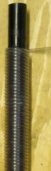
| Choke (390uH) | |
| Small Bolt (for choke core) | |
| Adjustable Spark Gap | |
| Silicon Cable (for primary coil and other wiring) | |
| Secondary Coil | |
| Toroid | |
| HV Insulators |
Tuning
Precise tuning of the resonant circuits for max output.
There are two resonant circuits in the Tesla coil part of the plasma gun which must be tuned to the same frequency. If the frequencies are not matched, the energy transfer will be very poor and your plasma gun will be little more than a noisy spark gap. The secondary coil’s resonant frequency is pretty much fixed. It is possible to make small adjustments by changing the size of the topload, but this is not very practical to do. Instead, it is simpler to choose a primary capacitor, and then adjust the number of turns of the primary coil to get the right resonant frequency. This can be done with a little calculation and then trial and error, but can be quite time consuming.
We used a signal generator and osciliscope for tuning the plasma gun, but it is possible to do it with a little circuit such as a Telsa Coil Tuner although it is not easy. Even after tuning, you may want to tweak the number of turns on the secondary coil to achieve maximum output. When tuning the secondary, keep it away from yourself or other objects as the proximity may alter the resonant frequency.
Once tuned you can also adjust the Power Pulse Modulator so that you get some good resonant charging of the capacitor. At certain frequencies the system will be more efficient o by slowly adjusting the frequency when it is running, it is possible to find the best setting. While making the adjustments, the spark gap firing rate is observed until a setting is found where the maximum firing rate is achieved.
with synchronous rotary spark gap
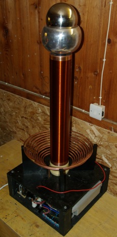
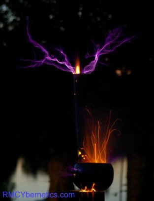
 This Tesla coil runs from a 220V mains input at around 1kW to give an awesome display of arcs and sparks. It has been made with a large secondary coil so that the topload has sufficient elevation for some of the experiments it will be used for and so that it can be upgraded to higher power levels in the future.
The content of this page is for anyone with an interest in Tesla coils and high voltage. We have tried to explain everything clearly and with enough detail so that it can be understood by anyone with some basic knowledge of electronics. We have also included useful formulae and the calculated result of them based on the parameters of this Tesla Coil. Based on the information on this page you should be able to reproduce your own home made Tesla Coil (at your own risk) so there is no need to buy any Tesla coil plans when you can get free Tesla Coil plans here! There are also other more technical details included on this page so that it is still of interest to those who are already familiar with building Tesla coils.
If you are not familiar with Tesla Coils, you could read our page that describes how a Tesla coil works.
![]()
WARNING: Tesla Coils are very dangerous high voltage devices!
If you do decide to build a Tesla coil or use any of this information, you should make sure you understand all the safety precautions needed. RMCybernetics are not responsible for anything you do as a result of reading this information.
 |
Input Voltage | 220V AC |
| Power Consumption | 1000W Max | |
| Max Arc Length | 74cm | |
| Capacitor | 20kV 0.06uF | |
| Spark Gap | SRSG(100BPS) | |
| Primary Turns | 3.5(Tuned) – 10 Available | |
| Secondary Turns | 550(0.56mm wire) | |
| Secondary Height | 61cm(Windings only) | |
| Secondary Diametery | 11cm | |
| Topload | Double Sphere | |
| Special Features | Secondary Gas Feed |
A Tesla Coil is used to convert relatively low voltage (like from the mains) to a very high voltage which oscillates at very high frequency. The result of this is lightening like electrical discharges from the top of the device. SRSG stands for Synchronous Rotary Spark Gap. This term describes the way in which the power is switched in the Tesla Coil. These devices were invented over 100 years ago which was before modern semiconductors and electronics. This meant that to switch power it was necessary to use mechanical methods like the SRSG.
This SRSG consists of two stationary electrodes and four interconnected electrodes on a spinning wheel. As the wheel spins, the electrodes pass by the stationary ones which briefly allows a spark to jump and transfer some power. This happens repeatedly as the wheel spins around.
The motor used to spin the wheel is a synchronous motor which means that it spins in phase with the mains frequency. In the UK this frequency is 50Hz which will cause the motor used here to turn 25 times per second.
The capacitor used in this Tesla Coil will be charged 100 times per second so we want the spark gap to switch the power every time the capacitor is charged. Having four electrodes on the wheel means that at every quarter turn of the motor, the electrodes line up and allow the energy transfer.
|
 |
 |
The photos above show the coil running at about 500W
Here you can see an arc hitting a grounded rod about 70cm away. The coil is running at 1kVA.
A long breakout point was needed to get good arcs due to the small topload
Housing
For holding the components together
 The supports for the coils were made on a piece of wood which was dried and sealed before use. Even very dry wood can attract high voltage discharge to it, so it is important that it is kept very dry and sealed to prevent it from absorbing more moisture. Plastic is much better to use but can be expensive and harder to work with.
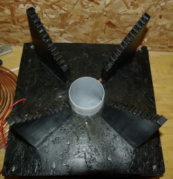
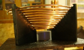
The supports for the primary coil were made by drilling a series of holes diagonally at equal distances in a block of wood. This was then cut down the center of the holes so that a series of grooves remain where the copper pipe of the primary coil would sit. These supports must be very well dried and varnished as the copper pipe could leak power into the wood.
The Grey pipe in the center is part of a 90 degree bend that fits into the push fit base of the secondary coil. This allows it to be mounted securely and easily.
Primary Transformer
Used to change the 220V mains input into 10,000V
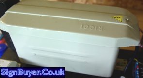
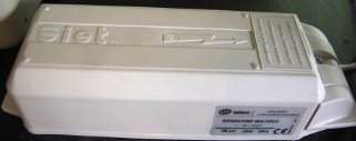
The transformer used is a Ricci NST (Neon Sign Transformer) rated for 10kV 100mA from Signbuyer.co.uk. This transformer is quite compact and comes with built in ground fault protection (GFP). There are a wide range of neon sign transformers available from Signbuyer which would allow you to make Tesla coils like this one or smaller. If you want bigger sparks, you can use two transformers in parallel to double the output power.
The primary transformer is what will determine the input power (and therefore arc size) to the Tesla coil. 10kV 100mA gives a maximum of 1kVA. (VA is equivalent to Watts, but is used because things get a little more complex with transformers). You can calculate the approximate size of arcs you can expect from the Tesla coil based on the input power. The length calculated is the straight line distance is that measured between the arcs origin on topload to a nearby grounded object.
Arc Length
L(cm)= 4.3 x √P(VA) = 136cm
This formula assumes that all the power from the input is transferred to the arcs and is not wasted in the conversion process. In practice this is not possible but the value given by this formula is a good guide.
 Based on the NST used in this coil the arcs theoretical limit is 136cm. The actual length we have got so far is 74cm. It may be possible to get more by having a tighter coupling between the primary and secondary coils but this would run the risk of causing damaging arcs between the coils.
NST’s have a small gap in the metal core which is used to limit the output current. This means that even with the output shorted, it wont overheat. Gapped transformers like these ideally should have a power factor correction (PFC) capacitor placed in parallel with its input. This serves to correct the shift in the phase of voltage and current caused by the large inductance of the transformer. It will work fine without it, but the power transfer will not be so efficient. The correct PFC capacitor can be calculated as follows.
PFC Capacitance
C = P/(2 x π x f (V2)) = 65.8uF
Where P = NST VA rating, V = NST input voltage, and f = mains frequency. It is not necessary to use the exact capacitance calculated, something less is fine.
It is common for people to remove the GFP when using the NST in a Tesla coil as the transformer is not connected to the mains earth anyway. It was left in for this coil as it can help prevent the transformer from becoming damaged if anything goes wrong.
 High Voltage Filter
Used to protect the primary transformer from damage cause by RF (high frequency) voltage spikes
The filter used is a common type of low pass filter known as a Terry filter which is often used in Tesla coils which are powered from an NST. The filter allows the 50Hz mains frequency to pass through easily but will provide a path to ground for the high frequency currents. It also includes a set of MOV’s which will short to ground if the voltage gets too high.
Resistors are mounted on heatsinks as they will get hot when in use. These and the other components must be spaced apart adequately so that sparks don’t occur between them.
To protect the 10kV NST used in this Tesla Coil, we used 14 of each of the following components; MOV/TVS – 1800V, Capacitors 1.6kv 3.3nF, Resistors 10M ohms 0.5W. In addition to these two 1k ohm, 100W resistors mounted on heatsinks are used. You can see how these are connected together in this Terry Filter Schematic. The the main schematics lower down to see how it is connected in the system.
Primary Capacitor
Used to store energy for releasing in pulses into the primary coil
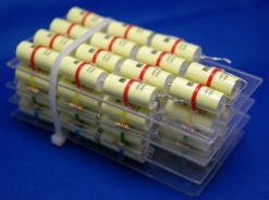
 With smaller battery powered Tesla coils the type of capacitor used is not too important. With larger coils like this it is important to use high voltage capacitors that are suitably constructed for handling large amounts of power. Large ones like shown below can be quite expensive so it is common to construct an equivalent capacitor from lots of smaller ones. This is known as an MMC. The one shown here was made by connecting fourteen 1500V 47nF polypropylene capacitors in series, then making 3 more identical strings. Each of these strings is equivalent to a 21kV 3.4nF capacitor. Connecting these four in parallel makes the overall capacitance 13.4nF. Usually a 10M resistor is placed across each of the small capacitors as a safety precaution. This capacitor was not used as it was too small for the NST.
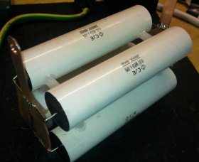
The primary capacitor used was made by combining six 20kV 0.01uF pulse capacitors in parallel. This capacitance is about as large as the 100mA NST can charge between each firing of the spark gap. With a static gap this capacitor would need to be smaller, but because the spark gap used here is synchronous, a larger capacitor is possible.
The value of capacitance that will work best with the transformer is calculated based on the mains frequency and the transformers impedance. You can calculate the transformers output impedance based on its output ratings
NST Output Impedance
Z(ohms)= E / I = 100k ohms
Where E = NST Output Voltage and I = NST Output Current
Now we know the output impedance of the NST we can calculate its capacitive reactance. The capacitive reactance give us the value of capacitor that the NST can fully charge during each half cycle.
Primary Resonant Capacitance
C(r) = (1/(2 x π x Z x f)) = 31.8nF
Using a capacitor that matches the capacitive reactance of the NST is not recommended. This would cause a resonant condition that would cause the voltage to rise, possibly damaging the NST and the capacitor. This is not the case for other types of transformer, but for the NST you would use a larger capacitor to prevent this resonant condition occurring. The actual value depends upon the type of spark gap used and is calculated as follows;
Actual Optimum Capacitance
Static Spark Gap:
C = C(r) x 1.618
Synchronous Rotary Spark Gap:
C = C(r) x 1.9 = 60.47nF
Where C(r) = the calculated resonant capacitance or capacitive reactance.
The capacitance of this capacitor combined with the inductance of the primary coil will determine the resonant frequency of the primary circuit. It is essential that this frequency matches the resonant frequency of the secondary coil so that energy can be efficiently transferred between the two and the voltage rise can occur.
Spark Gap
Used to discharge the capacitor into the primary coil by making and breaking a connection like a switch
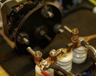 The spark gap used here is a synchronous rotary spark gap. This means that a motor spins around, moving some connected electrodes past the two main electrodes so that it will make a connection as it passes and break it again as it moves away. The spark still needs to jump but it is just about 1 or 2mm. The motor turns around exactly 25 times per second and is in phase with the 50Hz mains current. The four electrodes fixed on the rotating wheel are electrically connected and will connect the capacitor to the primary coil 100 times per second. The position of the rotating electrodes must match perfectly with the mains frequency so that the connection occurs when the capacitor is fully charged (at the peak of each positive or negative half cycle). An external control was made for controlling the phase of the motor so that it can be matched for optimum performance when it is running.
Also included is a safety gap which is just some electrodes spaced at a set distance that will allow the capacitor to discharge into the primary coil if the for some reason the rotary gap is not working right. When the motors phase is matched exactly or is slightly ahead of the primary capacitors voltage the safety gap should not be firing.
Primary Coil
Used to transfer energy to the secondary coil from the primary capacitor
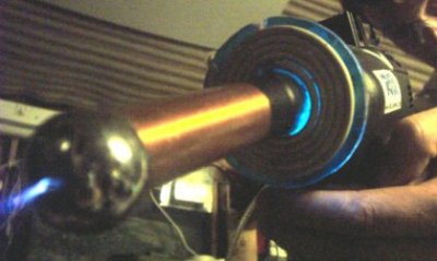
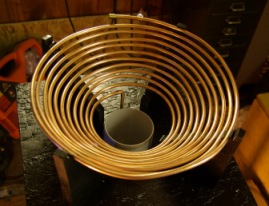 The coil is made from standard 6mm copper plumbing pipe. This is quite soft so it is easy to wind into a coil shape.
Copper pipe is used because it is thick and has low resistance (more efficient) and it is also easy to clip a wire to different points around the coil when tuning.
Wood should be dried and sealed as the copper pipe will be at high voltage when running the coil. The 10kV present on the coil is enough to jump to any unsealed wood which could cause fire or just hinder the coils performance.
 The coil was wound in a conical shape to allow for a good coupling to the secondary coil. If the power is upgraded in future it would be necessary to add a grounded strike rail above this to protect it from being hit by the Tesla coils output. It may even be necessary to replace the coil with one of a flatter design.
Secondary Coil
Used to step the voltage up higher still so that arcs can be produced from the topload
 The secondary coil was wound on a piece of standard 11cm diameter waste pipe. This piece had a push fit type connection at one end which would be used to mount the coil on the Tesla coils base.
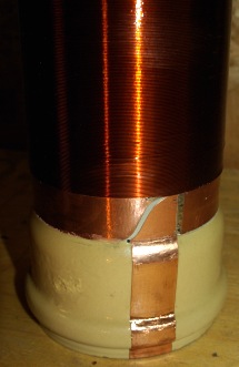
Each end of the coil was terminated with a final winding made from copper tape for neatness and easy connection. This loop of tape should not be continuous as it would act like a shorted turn and waste energy. A small cut is made so that the copper tape acts like the final turn of the coil connecting the wire to the RF ground.
At the base of the coil, the connection for RF ground is made by taking a strip of copper tape down the side and a few cm up again inside the pipe. When this end is pushed onto the support it meets with a matching area of copper which is connected to the RF ground This makes it very easy to place the secondary onto the base and have the RF ground connected without any solder or screw connection .
The same method is used for connecting the coil to the topload.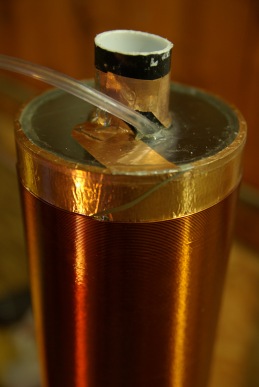
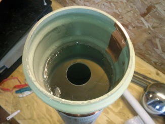
 Because this is an RMCybernetics Tesla Coil, we like to do it a little differently. Down the center of the secondary coil is a piece of 32mm drainage pipe. it is held in place by plastic discs which are epoxied in place. Around this central pipe is another pipe that is wound as a coil along its length. This pipe is about 20m long when uncoiled.
These pipes can be used for piping gasses or mechanical systems to the topload for performing various interesting experiments.
The secondary coil was wound on a simple jig with a geared motor at one end attached to a motor speed controller so that it could rotate slowly. The speed controller (our PWM-OCX) was linked to a foot pedal switch made from some wood and a microswitch. This allowed for the rotation to be started and stopped easily while keeping hands free for holding the wire.
When winding the coil it should be kept clean and the wire must be kept tight so that no kinks occur. After winding it was coated with polyurethane varnish to protect it from physical damage and to reduce the risk of the arcs flashing over the windings.
Topload
Used to store energy and to provide a place for sparks to come from
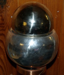 The topload is made using two separate spheres. The larger one is an upturned metal dome used in Van De Graff generators while the smaller one is a ‘floating sphere’ from a local DIY store. The smaller sphere has had a brass pipe fitted through the center so that it can be connected to the coiled pipe mentioned earlier. This sphere is just placed on the larger one which gives easy access to the pipes when changing experiments.
 The size of the topload will have an effect on the resonant frequency of the Tesla Coil. With the topload as shown the secondary coil had a resonant frequency of around 435kHz. Removing the small sphere makes it 455kHz and having no topload makes it 570kHz
A larger topload will give the secondary coil a lower resonant frequency and will also make it harder for a spark to break out. This allows the arcs to be larger than they would be if no topload were present.
Sometimes if a large topload is needed to get the right resonant frequency, a small point such as a metal rod or screw can be placed somewhere pointing outwards. This is known as a breakout point and will cause the sparks to come out at the end of it. This occurs because the point will have a large electric field gradient compared to the smooth round surface elsewhere.
When we upped the power from 500kVA to 1kVA steamers came from all over the surface of the topload. In order to get them to come from one place and be larger, a breakout of about 20cm was used.
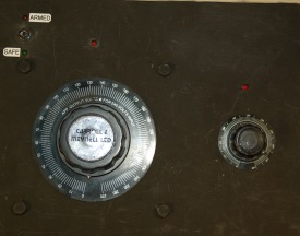 Control Box
The control box houses the two variac’s, a 120V transformer, a power relay, RFI filter, and a key operated switch.
The large variac is rated for 10A which is more than enough for the transformer used here. This variac allows a simple adjustment of the input voltage to the NST from 0V to 270V. The smaller variac is used to control the phase angle of the motor for the rotary spark gap. This allows for the timing of the capacitors discharge to be adjusted to match perfectly while the Tesla coil is operational.
Circuit Diagram
The diagram below shows the main tesla coil system components. The Terry filter is shown in simplified form in this diagram. The input to the circuit is 220V AV at 50Hz which is standard UK mains. This is first fed directly into an RFI Filter before then going to a large 10A Variac (T3). This variac allows the input voltage to the NST (T4) to be varied from 0 to 270V.
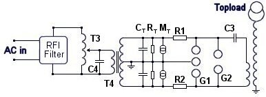
Only the RFI filter is connected to mains earth. The terry filter, NST, and secondary coil are connected to RF ground. The RF ground is made by forcing a large copper plated iron rod into the earth near the coil.
CT RT , MT, R1 and R2 are parts of the terry filter described earlier. In addition to this filter, a safety spark gap (G1) is used which will fire if the voltage is too high.
The main electrodes of the rotary spark gap ar. shown as G1 and connect to the main tank capacitor (C3) and the primary coil.
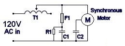 This diagram shows how the motor is wired to a variac for electronic phase control. This really makes things a lot easier to get the coil running well. A small variac (T1) passes power to the synchronous motor. The inductance of the variac combined with the capacitance C1 will allow small adjustments in phase of the synchronous motor. It is necessary to turn the variac to maximum to start the motor and allow it to lock on to mains frequency. It can then be turned back about 1/4 of a turn to adjust phase by about 25 degrees before the motor looses lock.
Experiments
The video below shows our first attempt at launching a rocket from the topload of the Tesla coil while it is running. The video is not great as we were a little afraid!
 To launch the rocket, a remote trigger for igniting the fuse was needed. This was made by using a home made air operated switch that connects a 12V battery to a 10 ohm resistor. The resistor heats up quickly and ignites the rockets fuse. The battery, switch, and resistor must all be contained within the topload sphere as they will be protected from the high frequency, high voltage. The airline passes down the inside of the secondary and out to a large syringe near the control box. When the syringe is pressed, the switch activates and the rocket launches.
So far we have only had one try at this as we can only do it when the weather is good. It is quite difficult to get a get photo of the rocket as it exits at high speed. We will need to do this experiment several times to get some god shots. In the photo above there is a large foil lined tube which contains the rocket. You can see as the rocket starts, the flames are leaking in various places. We will need to make a special topload for doing this again as to avoid damaging the coil.
 A kirlian photo is a photograph of electrical corona produced around objects under the influence of high voltages.
There are two common methods for producing kirlian photos. One is a little tricky, but the other method is quite simple if you have access to a few basic bits of equipment. You can see how to make a high voltage power supply supply on the DIY ignition coil driver page and others. If you are less familiar with building electronic circuits you can use our power pulse modulator to drive a hv spark coil as a high voltage source. The electrode plate can be made yourself or the easiest way is to use ITO coated glass.
We have a selection of specially made transparent electrodes for use as Kirlian Photo Plates which work great in this project.
![]()
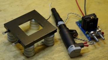
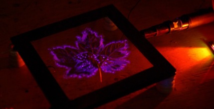
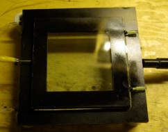
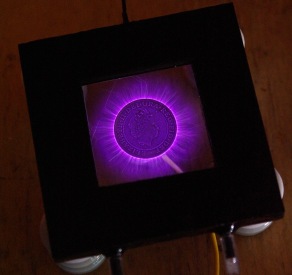
This method allows you to photograph or view electric field around object wit the naked eye. It works by creating a high voltage field between an object and a transparent electrode. The high voltage field causes ionisation of the air which is visible as a purple glow known as corona. The image above shows one of our Plasma Photo Plates resting on some high voltage insulators. You can use any insulator such as some plastic cups or glasses. Our electrode plates are provided with a filling syringe and caps so that it is easy to get started. Connected to the electrode plate is a high voltage spark coil which is being driven by our Power Pulse Modulator. The Power pulse modulator (PWM-OCXi) allows the high voltage coil to be driven with a variable frequency and power levels. This allows for different effects to be produced. At high frequencies, the plasma (or “aura”) tends to be softer and gives a smooth glow over most of the objects surface. At low frequencies the plasma tends to be longer and more jagged like lightning. It also tends to come mostly from the edges of the object rather than its surface.
First of all, the electrode plate must be filled with an electrically conductive solution. This is simply made by dissolving salt into ordinary tap water. You should add as much salt as will dissolve without making the water cloudy. Its is best to prepare the solution an hour before so that it has time to dissolve fully.
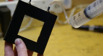
Connect the pipe to the end of the syringe provided and then draw some salt water into the syringe. (The amount needed will depend upon which size electrodes you have) Carefully put the other end of the pipe over one of the small plastic tubes on the edge of the electrode, tilt it as shown in the image and then slowly inject the solution into it. Make sure you go slowly to prevent leaks. Fill until a little solution comes out of the other plastic pipe, and then seal this with one of the caps. Remove the pipe and syringe and replace with the other cap. Wipe the electrode with a damp cloth and then make sure it is thoroughly dry and clean.
Take your sample such as a leaf or coin and tape it to the surface of the electrode as shown below.
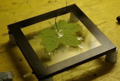
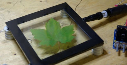
Tape a piece of wire to the back of the sample and connect the other end of this wire to ground. The ground connection should be the same as the ground or earth connection of your power supply. Turn the electrode over so that the sample sits underneath and place it on top of some insulators. You can use any non conductive object such as plastic cups or glasses. Connect the High voltage coil (or other HV power supply) to the metal connector on the electrode either directly as shown, or using a wire.
Connect all the other wires up so that it is ready to run. Familiarize your self with the layout as you will need to know where things are when you switch off the lights.
![]()
Turn the lights off and give your self a moment for your eyes to adjust to the darkness. Turn on the power and tune it to give the best possible image.
You should only have the power on for several seconds at a time. If it is on too long the sample could be burned or the high voltage could etch marks into the glass. Also if used at high power, the PWM-OCXI and coil will get hot so they will need to be allowed to cool. We recommend adding a push switch so that you just hold your finger on it to activate the device while taking a photo. You will need a camera with a good lens or high ISO setting so that it can take good pictures in the dark. Using different settings such as shutter time will allow you to get different quality photos.
![]()
You can also try an alternative setup using two or more electrode plates together as shown below. This allows you to add samples without having to stick them down or attach wires to them. It also allows for a wider range of effects.
Here you can see one large plate at the bottom and a medium sized one on top. You can use any sized plates combined together but larger plate will need more power. The sample is placed between the two plates and the ground connection is made to the second plate. You can try having the grounded plate on top of the HV plate or visa-versa for different results.
This alternative method uses photographic plates or paper which can be expensive and hard to find. It can also be tricky to do correctly. The advantage though is that you can sometimes get images with various colours showing. The sample such as a leaf is placed directly onto the photographic plate. When exposed to high voltage the corona will effect the photosensitive chemicals in the photographic plate in different ways depending upon the intensity of the discharge.
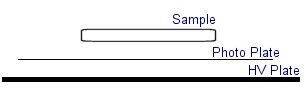
This diagram shows how the sample to be photographed is placed on top of the photosensitive paper with an insulated metal plate below. The lower plate is connected to a high voltage source of several kV. While the sample is usually grounded for brighter results.
Obviously all this setup must be kept in the dark as to avoid exposing the photo paper to light. The power is usually switched on for around 30 seconds to get a good enough image.
 If you don’t have photographic paper you could use the film from a polaroid camera. Polaroid cameras will eject a protective layer of card when you first insert a film. You can use this feature to develop your exposed film.
To make a kirlian photograph using polaroid film you should remove one film from the cartridge and expose your sample just as described above. After you have exposed the film, carefully place it back inside the film cartridge in the top position. Load the cartridge back into the polaroid camera and it will immediately eject the top film. When the film is ejected it passes between a pair of rollers which spread the developing chemicals over the image so that it is fixed and now safe to expose to the light.
 Many people claim that this sort of photo is showing the “life force” or “aura” of living things. This is something many pseudoscientists are using as so they can sell you these sorts of cameras for thousands of dollars. This page should hopefully show you how simple they actually are and that it is just simple corona and ionisation effects that are being observed.
There are also claims of a “Phantom Leaf” experiment where a kirlian photo of a leaf with a piece cut away showed an image of the full leaf. Proponents of this idea claim that this “proves” that the “Life Force” lingers on after the original piece of leaf is removed.
The only legitimate reasons for any phantom images would be caused by water or etching on the surface of the glass plates of the equipment. Any claims of anything else are totally unfounded and such people should not be taken seriously. If you try moving the cut leaf to a different camera, or use new clean glass plates then no “phantom” effect is observed.
You can even take kirlian images of things like your finger tips or whole palm. There are people who claim that you can diagnose illness from the shape of the images produced. This is really outlandish any many people are taken in by these scammers. There are charts that even relate each finger tip image to a certain part of the body or emotional states. These claims are just pure fantasy, and are another method used to make money selling expensive cameras.
Some of these sites often use scientific terminology in all sorts of inaccurate ways and even list quotes of support from people who are apparently Doctors or experts in something. The fact is that there is no legitimate reproducible experiment that gives evidence to support any such claims.

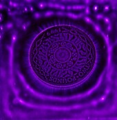
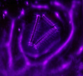
This kirlian photo shows a £2 coin between two of the electrode plates. The surrounding dots are caused by tiny amounts dust and dirt on the glass surface.
>
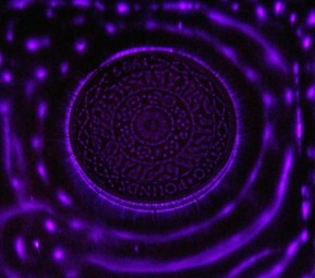
This kirlian photo shows a close view of the same coin and with a higher frequency supply. You can see rings or waves around the coin.
Another shot of the waves around the coin

This is a photo taken when no sample is placed between the plates. All the little dots are probably dust although we had tried to clean the surface thoroughly.
Some of these dots would move around the electrodes due to electrostatic effects.

Same image with longer exposure time on camera.

This is a photo of the leaf shown in the instructions above
By adjusting the frequency while watching it, you can see the glowing corona move around different parts of the leaf.
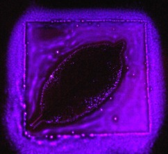
Another leaf image at high frequency.
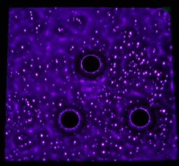
Three Neodymium Magnets between the electrode plates.
A single Neodymium magnet
A bunch of little magnets. Notice the rings or waves again
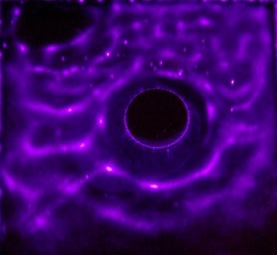
The £2 coin at low frequency under a single electrode.

You can see more Kirlian photos and high voltage plasmas on the Plasma Page

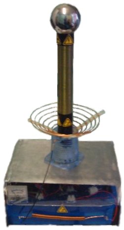
The aim of this design was to get the highest voltage (or longest arcs) possible from a single self contained unit.
![]()
This coil operates from 12V or 24V SLA batteries. A pair of car ignition coils are used to provide around 20kV for charging the capacitor bank. The ignition coils are driven by a variable frequency square wave from a 555 timing chip and four large transistors (2N3055).
 |
Input Voltage | 12 – 24V DC |
| Power Consumption | 250W Max | |
| Max Arc Length | 25cm | |
| Output Voltage(approx) | 250kV | |
| Primary Transformer | 2 x Car ignition coils in parallel – 20kV | |
| Capacitor | MMC 20 kV | |
| Spark Gap | 5 x 6mm pipes, Variable | |
| Primary Turns | 850 | |
| Secondary Turns | 850 | |
| Secondary Height | 40cm | |
| Secondary Width | 5cm | |
| Topload | 10cm Sphere | |
| Special Features | Plasma/Flame discharge terminal Battery powered Fully portable Variable coupling Basic power Management |
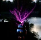
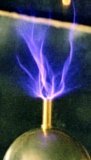
A pipe from a hole in the top of the sphere and down the inside of the secondary coil is used to supply gas to form a type of plasma electrode.
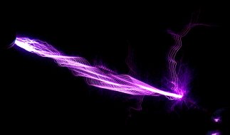
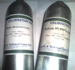
 Using Butane gas and air, a blue flame can be used as an interesting discharge terminal. The heated CO2emissions provide a low pressure channel to conduct the electricity more easily than air. This produces a large plasma column above the flame. At certain spark gap discharge rates the plasma column can be made to resemble a stable double helix formation. Small quantities of other gasses such as neon or helium can be mixed with the butane to produce slightly different colours and effects. The table below should help you find some of the components needed for this project.
| Component | Max Voltage | Source |
|---|---|---|
| Ignition Coils | ~20kV | Click Here |
| Capacitor Bank | 20kV | Click Here |
| HV Diode | 30kV | Click Here |
| Power Transistor | 400V | Click Here |
| Neon / Helium | n/a | ST Gas |
| Control Circuit | n/a | Click Here |
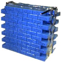 Capacitor Bank – The capacitor used in this project was made by combining a large number of lower valued capacitors. By connecting smaller capacitors in series the overall voltage they will tolerate is increased. To obtain a higher storage capacity (capacitance) the capacitors can be connected in parallel. This type of capacitor bank is known as an MMC (Multi Mini Capacitors). The next version of this project will use specially designed large pulse discharge capacitors. These capacitors can be more efficient than an MMC, but they can be expensive and hard to find.
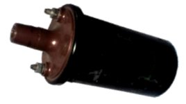 Primary Transformer – Ignition coils (Induction coils) obtained from a scrap yard are used for this design. The old ignition coils provide a very cheap way of generating a high voltage for charging the capacitor. The voltage increase in an ignition coil is not determined by the turns ratio like in normal transformers. The secondary voltage depends upon the rate of change of the current in the primary coil. Older ignition coils such as ones from a scrap yard may not work as well as new ones. Over time the insulating oil inside the casing becomes less effective and can lead to internal arcing. This can damage the transistors and the control circuit, rendering them useless
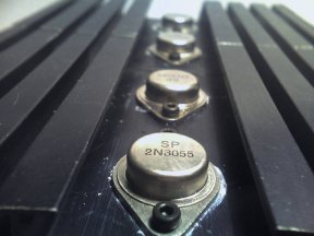 Control Circuit – The control circuit is based on a simple oscillator provided by an NE555 timer chip. The square wave pulses are sent to a set of four 2N3055 power transistors mounted on a large heat sink. These transistors can switch a good amount of power quite quickly, but they can be sensitive to voltage spikes caused by feedback in the circuit, or faulty ignition coils. The Ignition coil driver circuit shown below shows how the signal from the 555 chip is pre-amplified, so that the large transistor array can be driven effectively. Using 2N3055 transistors in this way is not ideal, but it is what we had available at the time for the project. Modern IGBT transistors are much more effective and less
prone to failure from voltage spikes.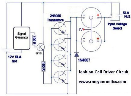
The output from the ignition coils is rectified (converted to DC using diodes) so that it can charge the capacitor bank C1 shown below.
 Coils – The primary coil is simply made from 2mm enameled copper wire, wound around a plastic stand. There are six turns in total, but the connection is made at about 4.5 turns when tuned. The secondary coil is wound from 0.4mm enameled copper wire around a plastic drainage pipe.
Safety – Attached to the capacitor is a short circuit switch that is activated by a long plastic handle. This is used to make sure the capacitor is fully discharged, and cannot recharge whilst making any manual adjustments. There is also a switch to isolate power from the ignition coils that is activated using a insulating pull cord.
 Special Features – This project has several extra features compared to a common Tesla Coil. The topload sphere has a small hole to allow gas to be emitted. A 5mm plastic pipe runs down the inside of the secondary coil, and out of the plastic base.
This allows the gas to be piped in, without interfering with the normal operation of the Tesla Coil.
 Future Developments – This project is currently being upgraded. The new design aims to achieve a higher power throughput. By using more ignition coils in parallel it should be possible to increase the size of the spark gap, or to fire it more rapidly. New ignition coils will used instead of the second hand ones for improved stability. The new design also incorporates voltage and power monitoring features. It also has a neat metal finish and multiple outputs so that it can be used as a multi purpose portable high voltage power supply
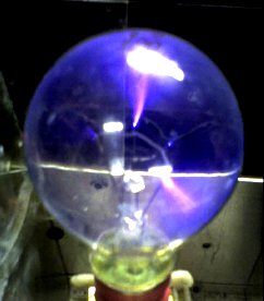 There are all sorts of ways to make a plasma globe. This page deals will detail how to make one using a small amount of easily obtainable components. A normal transparent light bulb can be used as a plasma globe simply by connecting it to a high voltage, high frequency source. Most light bulbs contain low pressure Argon gas to prevent the hot filaments from burning. Fortunately this arrangement is also ideal for making contained arcs of plasma. The power supply required for the plasma globe would preferably be a high voltage, high frequency AC type, which could be made from an ignition coil, like the ones used in the Homemade Tesla Coil project. The schematic below shows a driver circuit, for more details see the Ignition Coil Driver page. We also sell a ready made ignition coil driver (shown in the pictures) which also includes extra features.
| WARNING: High Voltage Devices! |

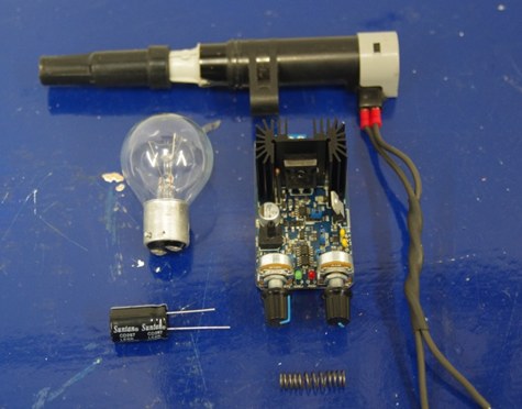 The following parts are used for the video demo of this project;
First the spring must be attached to the bottom of the light bulb; this can be done using a bit of tape. The spring is used to ensure a connection between the bottom of the bulb and the high voltage output within the end of the ignition coil. Next, the bulb and spring are fixed tot he end of the ignition coil with some more tape.
The ignition coil is connected by two wires to the PWM circuit at the L+ and L- terminals, and the power supply is connected to GND and V+. Also connected to V+ and GND is the electrolytic capacitor. This is connected close to the circuit board and is used to keep the DC input stable. It is important to note that the orientation of the capacitor must be correct. To know which way around it should go look for the longer leg (which indicates the positive) there is also often a stripe on the side of the capacitor to indicate the negative side.
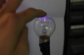 The settings on the PWM circuit will need to be adjusted so that good streamers become visable in the coil. Always begin with the duty setting at zero then slowly turn it up to around 50%. The frequency setting is then adjusted while observing the apperance of the plasma inside the lightbulb. At some frequencies no plasma will be seen, while when at the right frequency there should be lots of streamers dancing around inside the bulb. The frequency needs to be fairly high and the buzzing sound from the coil will become so high its is amost inaudiable.
When operating the circuit great care must be taken as the ignition coil could output around 20-30kv when using around 15V, 5A from the power supply.It should not be touched as it will give a nasty shock.
 Polypropylene Capacitor 1kV 330nF
$2.63
Polypropylene Capacitor 1kV 330nF
$2.63  Solid State Relay 40A
$17.19
Solid State Relay 40A
$17.19
 HV Spark Coil
$37.03
HV Spark Coil
$37.03
 Power Pulse Modulator - PWM-OCXi v3
$144.85
Power Pulse Modulator - PWM-OCXi v3
$144.85
 Power Pulse Modulator - PWM-OCX v2.2
$128.00
Power Pulse Modulator - PWM-OCX v2.2
$128.00