-
×
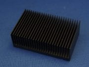
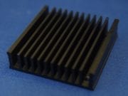 Heatsink 50 x 50 x 12.8mm
1 × $13.31
Heatsink 50 x 50 x 12.8mm
1 × $13.31
Subtotal: $13.31
Heatsink 50 x 50 x 12.8mm
1 × $13.31 Subtotal: $13.31
This section gives details of many DIY science projects and equipment which can be made at home.
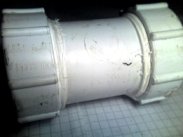 This underwater camera is made by housing a small security camera inside a pressure tight container. This setup will work perfectly in clear water, but with increased water turbidity, lights will be necessary to improve performance. Construction details for the lights and housing are shown below.
This plumbing accessory form a local DIY store forms the main part of the housing. It was chosen for its compact size, and it allows both ends to be easily removed so the components remain accessible.
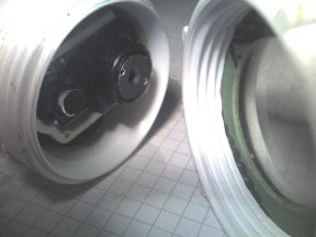
 The two end caps are not fully closed. This allows a small perspex window to be added for the camera to see through. A perspex disc should be cut to fit neatly inside the cap with an o-ring either side. PTFE tape wrapped around the screw thread will ensure a tight fit when screwing on the caps.
The cable is sealed in the middle of another perspex disc. This allows the ends to be unscrewed without twisting the cable. Layers of Polymorph and epoxy resin are built up either side of the disc, and around the cable to form a strong flexible seal.
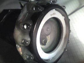
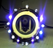 The light source is an array of bright LED’s. The LED’s shown here are from surplus parts and are not the most effective light source for a camera. The best LEDs would be either white or infra red, as the camera will respond best to these. The LEDs and resistors were mounted on a plastic strip which is formed into a ring to fit over the end of the camera housing. They are sealed using Polymorph and epoxy resin.
The lights shown here are a combination of blue, ultra violet, white, and infra red LEDs. There are fifteen in total. It looks pretty cool, but a white or IR light would be better. The power for the LED’s was taken from the same 12V battery used for the camera so it was neccesary to reduce this power to a lower level for them. To do this a power pulse modulator was used with the frequency set high and the pulse width set very low. This served as a dimming module for the LEDs so the brightness could be finely contolled.
Check out he video captured with this camera in the Alsager Mere section.
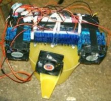 This device utilises the cooling effect of peltier heat pumps in order to extract water from the air. The device was used in a damp basement and could collect about 500ml per day. The erratic wiring in the image make this device appear much more complex than it really is. There are a large number of wires because several different sized heat pumps were used, and each requires a different voltage. The six fans all ran from 12 volts. To provide the various voltages to the device a standard 500W ATX PC power supply was used. This type of PSU can be very useful for various experiments as they can provide a range of voltages simultaneously with a reasonable power output, and they are also overload protected. An alternative to using the set voltages of an ATX PSU is to use a pulse width modulation circuit such as a power pulse modulator. This can be used to finely adjust the power to a peltier cooler so that it is operating at optimum levels.
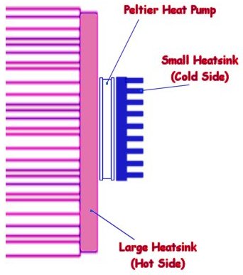
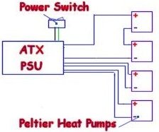 The device works by cooling the small blue heatsinks in the centre of the image. These are cooled to about 0 degrees Celsius (dependent on ambient temperature) which causes water to condense on the fins. When enough water has built up between the fins it will drip into the container below. The fan at the front simply keeps the air flowing over the cold fins, whereas the other fans are used to remove the heat from the heat pumps. In this image you can see a heat pump (peltier module) between the hot and cold heatsinks. Although this device is a useful demonstration of scientific principles, it is actually not incredibly practical or efficient.
This device is very easy to construct, and can collect a surprising amount of water for its small size. When a peltier module is attached to a DC source it will begin to move heat from one surface to the other. The side receiving the heat needs to be cooled using large heatsinks as the module itself will generate excess heat due to the current flowing in the device.
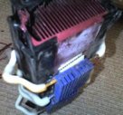
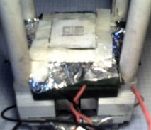 The aim of this project was to create a simple device capable of keeping components as cool as possible using common parts and materials. The device shown here is capable of maintaining a temperature of approximately -50° C.
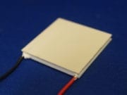
The image on the left shows the exposed surface of a peltier heat pump which normaly sits under a well insulated containter with a metal base.
A selection of peltier heat pumps are stacked on a large heatsink (with fan) and surrounded by insulating material, except for the cold face. Using the thermoelectric effect of the Peltier elements, heat can be rapidly drawn away from this surface, but only as long as the heatsink is able to dissipate into she surrounding air. A large heatsink and fan can be found in computer shops as they are necessary for keeping your computers processor cool.
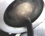
Simply sticking a component to the surface of the heat pump will provide quite effective cooling, but only if there is a large amount of contacting surface area. For more rounded or uneven shaped components, such as laser diodes, it is possible to use a very cold liquid to surround the device. This liquid must be able to withstand very low temperatures without freezing, and be highly volatile (evaporates easily). Something like liquid Nitrogen or Helium would be great, but that’s not something you can just pick up from your local hardware store. This projects uses ‘Freezer Spray’ which can usually be found in shops selling plumbing accessories. This spray evaporates rapidly on contact with room temperature objects drawing the heat way from it. By slowly spraying the Freezer Spray into a small container such as its lid, it is possible to collect it as a liquid. The liquid can be put in a small metal container which sits on the surface of the cold heat pump. This metal container is also surrounded in insulating material such as polystyrene.
When the heat pumps and fan are active it should be possible to prevent the liquid from evaporating, allowing components to be submerged for cooling.
Most peltier heat pumps / thermoelectric modules require some odd non standard DC voltage (8.4 for example). While such a device would work fine on a lower voltage you would not be getting the full cooling potential of the peltier element. A good way to power these devices is by using pulse width modulation so that you can adjust precisely the average power flowing through the device. Our power pulse modulator makes an ideal power supply for peltier modules.
Available Parts: Heat Pumps, Thermal Compound, Power Control Circuits, PSU, Heatsinks
A simple vibrating platform can be made from a piezoelectric sounder mounted on a plastic tube. The piezo sounder can be connected to a signal generator or even a PC sound card. By placing a small amount of powder or fluid on the sounder, various patterns and motions can be seen depending upon the applied frequencies. This system is known as Cymatics.
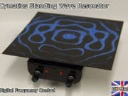
This image shows a pattern formed by a fine powder vibrating at a single, mid audio range frequency. Depending upon the size of your sounder and the materials used, the patterns will emerge at a range of frequencies.
Sometimes a pattern will only remain stable at one exact frequency, whereas other patterns will emerge over a broad range frequencies. By mixing signals together more complex patterns can be formed. If you don’t have signal generators handy try using classical music as it contains a great deal of harmonics and mathematical ratios within the sounds. Other types of music may work too, but the drum beats tend to destabilize the patterns.
We now have a fantastic Cymatics device available to buy with built in audio generator which is demonstrated in the video below.
Different materials will respond in different ways to the vibrations due to varying density or particle size and shape. Materials can also be separated or made to flow through each other.
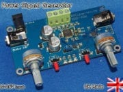
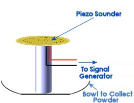 This diagram shows a flat Piezo sounder glued to the top of a small section of tubing for support. The connecting wires should be supported by attaching them to the tube. It is important that the wires are not tight as they may prevent the piezo sounder from oscillating fully. The wires can then be connected to an signal generator such as the DIY signal generator, power pulse modulator, or even a PC headphone output.
There should only be a pinch of powder such as salt placed on the sounder to see the effect. The sound should be adjusted whilst watching the surface to see how it responds. Make sure the sounder is as level as possible otherwise the powder will slide off before any patterns are formed.
You may notice that a certain frequencies the powder will jump into the air quite suddenly, destroying any patterns. This occurs due to resonance, and turning down the volume should allow you to form patterns at the resonant frequencies.
Liquids will form patterns with a very high resolution. High audio frequencies can create very fine pattern, barley visible to the naked eye. A laser beam, reflected by the vibrating surface can be used to magnify the effect. The reflected laser beam can produce an image on a screen, which will represent the vibrating surface.
Price range: $193.18 through $233.14Select options This product has multiple variants. The options may be chosen on the product page
The projected images can look like 3D holograms, and it is often quite difficult to see how the projected pattern relates to the actual pattern on the reflective material.
You can make much larger versions of this project using a speaker with a flat playe replacing part of the cone. Details are shown in the comments section below. To drive a speaker you will need an amplifier to give a good supply of power to the speaker. An alternative is to use a high power signal generator such as a power pulse controller.
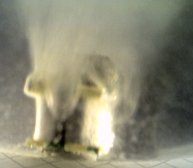
If the piezo transducer is driven at very high, or ultrasonic frequencies, and with a large amplitude it is possible to ‘atomize’ liquids such as water. This creates a fine mist that resembles steam in appearance. Such mists are actually tiny droplets suspended in the air yet they behave as if they were all part of a single dense fluid medium.
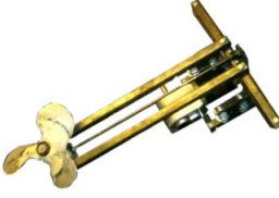 This is a battery powered motor for a small rowing boat. The motor used is from an electric wheelchair which ran from 24V. The motor has a built in reduction gearbox to provide a large torque to the wheels on the wheelchair. This gearing ratio was far to high for the propeller. The prop needs to turn much faster in order to generate the right amount of thrust to move the boat.
Fortunately the motor used had a small part of the main rotor protruding from the opposite end to the gearbox which was sufficient to attach a sprocket. This sprocket was linked with a chain to another sprocket on the main axle. This axle was then connected to a 90 degree 2:1 gearbox from a cheap angle grinder which was then attached to the propeller.
The propeller is from an old barge and is a little larger than necessary, but the motor provides just enough power to compensate.
The control system uses a pulse width modulation system for a smooth speed control and efficiency. The circuit used is based on the power pulse modulator but with the high voltage MOSFET being replaced by an array of lower voltage high current bipolar transistors so that the huge currents demanded by the motor could be tolerated.
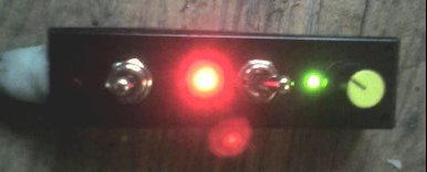
The other switches on the control box are for forward/stop/reverse and to choose between 12V and 24V operation. These are simply large power switches that are used to directly switch the power as necessary.
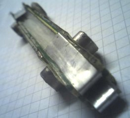 Based on the image on the left, it is possible to make a simple MHD thruster, just powerful enough to propel a toy boat.
This type of thruster generates magnetic fields by passing an electric current through a liquid conductor, such as sea water. Using another magnetic field, the liquid can be pushed in a chosen direction, therefore generating thrust. You can easily make one of these devices from household materials and a couple of neodymium magnets. In the diagram below the small arrows represent the intersecting electric and magnetic fields. the large blue arrow represents the flow of water.
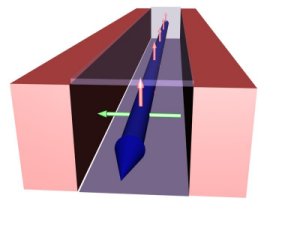 Two opposing inner faces of a rectangular plastic tube are covered by metal strips. These are the main electrodes and should have a connection for a battery. Magnets are attached on the outside of the tube so that they are attracting each other, and are at 90° to the electrodes.
The metal strips here are cut from a thin Aluminium sheet, but you can just use foil although it wont last as long. The electrolysis and salt water corrosion soon eats away at the metal, but foil should last just long enough to see it working. The best sort of electrode would possibly be made from carbon. A good power source for this device would be a pulse width modulated supply such as our power pulse modulator. This would allow you to adjust the frequency and width of electical pulses so that you could get the optimum thrust from your design.
To learn how a MagnetoHydroDynamic thruster works, see the Propulsion section.
 This setup shows the electrodes closer together than the magnets. The combination of magnets used in this device were not strong enough to move the electrified water with any decent force. At only 1.5V in salty water, large amounts of electrolysis occurs, but the water does generally flow in one direction.
The key to getting the best performance it to have the strongest magnetic field you can get across the gap between the electrodes.
Also make sure the magnets are behind the plastic or insulated somehow. You don’t want them shorting out the electric current in the water.
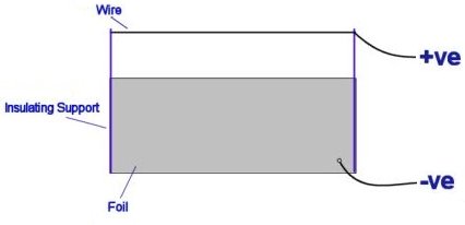
The diagram below shows a EHDT in its most basic form. It consists of a fine wire, suspended above a sheet of Aluminium foil, by a lightweight insulating support such as balsa wood. If a high voltage DC source is connected as shown, a thrust will be produced, propelling the device in the direction of the positive wire. This thrust is due the motion of air, or any other dielectric (insulating) fluid around the device, as described below.
![]() WARNING: This project requires the use of dangerous high voltage electricity!
WARNING: This project requires the use of dangerous high voltage electricity!
The top sharp electrode ionises the air. If the electrode is positive, free electrons in the vicinity will accelerate towards it, and strip off other electrons from the air molecules around the sharp wire. A cloud of heavy positive charges is thus formed, and the avalanche of electrons approaching the sharp electrode account for the corona & ionisation current.
In their mad rush from the ion emitter to the smooth negative electrode, the positive ions bump into neutral air molecules-air particles without electric charge. The force exerted on them by the electric field is offset by the force of friction caused by collisions of the ions with the neutral air molecules. As a result, ions drift through the air gap with an approximately constant velocity Vd, that is proportional to the electric field given by Vd=kE, where the proportionality constant K is called the ion mobility, the highest the value the more mobile (faster) and the less friction is offered.
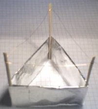 EHDT Construction Details
Gently fold over the top a long edge so you are left with a long rounded edge, and a long sharp edge opposite. The rounded edge will be closest to the corona wire.
Fold the strip into three equal sections, plus a little extra for sticking the ends together.
Using a small amount of glue, attach three lightweight balsa wood supports, and stick the two short edges of the foil together to form a triangle.
Loop a thin wire around the supports so that it is a few centimeters from the foil, and leave a long wire for connection to the power supply.
Connect another long wire to the foil, in a position away from the other trailing wire.
The voltage required to power the lifter will depend upon its size but it is usually above 10kV. By moving the top corona wire closer to the foil, more thrust can be produced. If it is too close arcs will jump between the electrodes, causing it not to fly.
Place the thruster on an insulating surface (a table), and away from any metal objects.
Attach the two wires to the table so that the thruster can hover, whilst being held down by the wires.
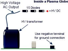
 For a tiny Lifter the output of a plasma globe PSU and a HV diode can be used, but for a larger device a larger transformer may be needed.
The picture on the left is of the inside of the plasma globe, and you can make the output of this DC by connecting it to a HV diode.
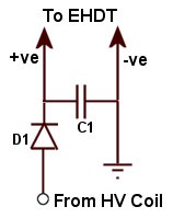
For larger lifters, a simple adjustable supply can be made by driving an high voltage coil with a power pulse modulator and then rectifying the output with a high voltage diode and capacitor as shown here. The diode D1 should be rated for high voltage such as 20kV, 100mA as to withstand current pulses from accidental shorts. The capacitor C1 should also be rated for 20kV. The capacitor is not essential but it can help improve performance and add some protection for the diode. The capacitance can be any value, but bigger is better.
The pulse modulator allows you to vary the output voltage very easily so that you can get more control over the performance of the lifter.
 The valveless pulse jet engine or pulse detonation engine is the most simple type of jet and is therefore popular among hobbyists as a DIY project. it is often referred to as a ‘tuned pipe’ because its operation depends upon making the parts the right size and shape so that it fires, or resonates at the engines natural, fundamental frequency. This type of jet propulsion does not need any type of turbine, turbofan, or propeller, making it much less complex than a typical turbojet. In a turbojet the turbine or turbofan is used to compress the fuel/air mixture in the combustion chamber so that it is more efficient and powerful.
This jet engine has absolutely no moving parts and it relies on the simple shape of the combustion chamber and exhaust for it to function. The fuel to the jet is provided at a constant rate, but it is detonated in pulses. After each explosion there remains a lower pressure area inside the combustion chamber. This is immediately filled as air rushes back in and mixes with the fuel feed ready for detonation again.
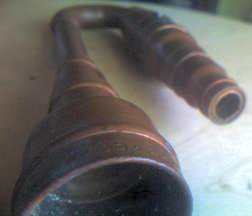
This example of a homemade jet engine is about as simple as it gets, but it could not be used for propulsion purposes because it is only safe to operate for a short time. The main body of the pulse jet engine is made from copper pipes and various adaptors. The combustion chamber is made from two copper adaptors that have been cut and soldered together. Copper is an excellent thermal conductor which helps to spread the heat throughout the jet, but solder melts very easily so if the jet engine were allowed to run for more than a few seconds this part could come apart. This was enough to demonstrate the principles of operation which is all this DIY jet engine was designed for. If you wanted a working model for providing thrust, it would be necessary to consider different materials as a running jet will get very hot.
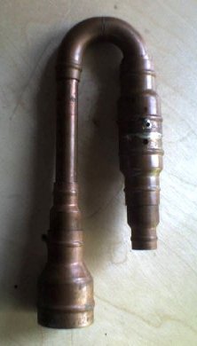 These images show the basic ‘tuned pipe’ without the spark plug and gas supply. Tuning was achieved by altering the length and width of the parts used. This was quite simple as there are wide range of plumbing parts that will easily fit together.
The fuel was provided from a cheap blow torch and was injected into the combustion chamber using fine brass tubes bought from a local hobby shop. This chamber also contained a tiny homemade spark plug. The spark rate could be controlled by varying the power to a HV capacitor connected in parallel with the spark plug.
The power supply for the tiny spark plug was made from a mini cold cathode PSU connected to a HV diode and capacitor. An alternative is to use an ignition coil and an ignition coil driver circuit.
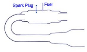 The spark plug its self was just a single wire inside a small glass fuse. This wire was connected to one capacitor terminal (live) and the body of the jet engine was connected to the other terminal (earth). The spark would jump from the tip of the wire to the inside of the combustion chamber to ignite the fuel mixture.
The simple design and adjustability of this jet means that a wide variety of fuels can be used. The most common fuel used is kerosene and propane, but common lighter gas will work for this basic demonstration. Click here for More information on Jet Engines.
 Induction Heater Circuit - CRO-SM3
Price range: $159.89 through $177.21
Induction Heater Circuit - CRO-SM3
Price range: $159.89 through $177.21
 Polypropylene Capacitor 400V 330nF
$3.32
Polypropylene Capacitor 400V 330nF
$3.32
 Power Pulse Modulator - PWM-OCXi v3
$145.88
Power Pulse Modulator - PWM-OCXi v3
$145.88
 Power Pulse Modulator - PWM-OCX v3
$128.91
Power Pulse Modulator - PWM-OCX v3
$128.91
 Solid State Relay 40A
$17.31
Solid State Relay 40A
$17.31