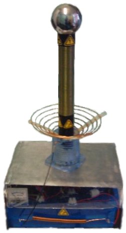
A DIY Mini Tesla Coil
DC Powered with Plasma Output
The aim of this design was to get the highest voltage (or longest arcs) possible from a single self contained unit.
![]()
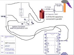
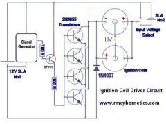
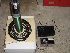
This coil operates from 12V or 24V SLA batteries. A pair of car ignition coils are used to provide around 20kV for charging the capacitor bank. The ignition coils are driven by a variable frequency square wave from a 555 timing chip and four large transistors (2N3055).
 |
Input Voltage | 12 – 24V DC |
| Power Consumption | 250W Max | |
| Max Arc Length | 25cm | |
| Output Voltage(approx) | 250kV | |
| Primary Transformer | 2 x Car ignition coils in parallel – 20kV | |
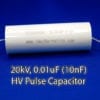
| Capacitor | MMC 20 kV | |
| Spark Gap | 5 x 6mm pipes, Variable | |
| Primary Turns | 850 | |
| Secondary Turns | 850 | |
| Secondary Height | 40cm | |
| Secondary Width | 5cm | |
| Topload | 10cm Sphere | |
| Special Features | Plasma/Flame discharge terminal Battery powered Fully portable Variable coupling Basic power Management |
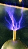
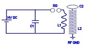
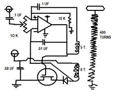
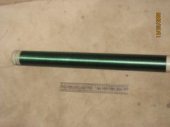
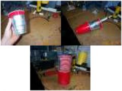
A pipe from a hole in the top of the sphere and down the inside of the secondary coil is used to supply gas to form a type of plasma electrode.
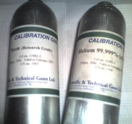
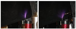
 Using Butane gas and air, a blue flame can be used as an interesting discharge terminal. The heated CO2emissions provide a low pressure channel to conduct the electricity more easily than air. This produces a large plasma column above the flame. At certain spark gap discharge rates the plasma column can be made to resemble a stable double helix formation. Small quantities of other gasses such as neon or helium can be mixed with the butane to produce slightly different colours and effects. The table below should help you find some of the components needed for this project.

| Component | Max Voltage | Source |
|---|---|---|
| Ignition Coils | ~20kV | Click Here |
| Capacitor Bank | 20kV | Click Here |
| HV Diode | 30kV | Click Here |
| Power Transistor | 400V | Click Here |
| Neon / Helium | n/a | ST Gas |
| Control Circuit | n/a | Click Here |
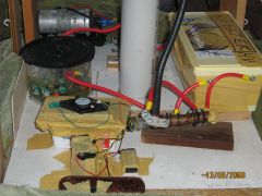
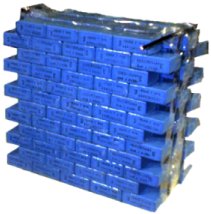 Capacitor Bank – The capacitor used in this project was made by combining a large number of lower valued capacitors. By connecting smaller capacitors in series the overall voltage they will tolerate is increased. To obtain a higher storage capacity (capacitance) the capacitors can be connected in parallel. This type of capacitor bank is known as an MMC (Multi Mini Capacitors). The next version of this project will use specially designed large pulse discharge capacitors. These capacitors can be more efficient than an MMC, but they can be expensive and hard to find.
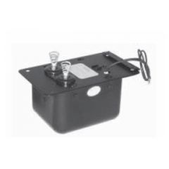
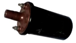 Primary Transformer – Ignition coils (Induction coils) obtained from a scrap yard are used for this design. The old ignition coils provide a very cheap way of generating a high voltage for charging the capacitor. The voltage increase in an ignition coil is not determined by the turns ratio like in normal transformers. The secondary voltage depends upon the rate of change of the current in the primary coil. Older ignition coils such as ones from a scrap yard may not work as well as new ones. Over time the insulating oil inside the casing becomes less effective and can lead to internal arcing. This can damage the transistors and the control circuit, rendering them useless
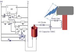
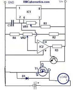
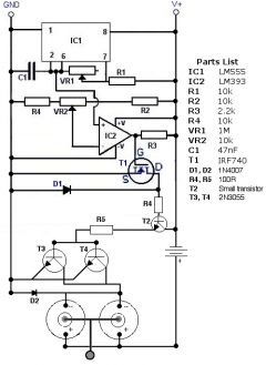
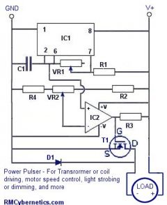
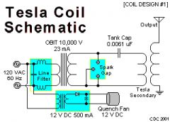
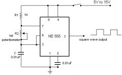
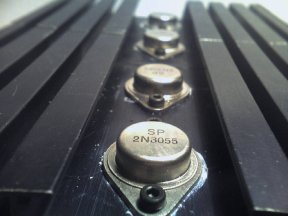 Control Circuit – The control circuit is based on a simple oscillator provided by an NE555 timer chip. The square wave pulses are sent to a set of four 2N3055 power transistors mounted on a large heat sink. These transistors can switch a good amount of power quite quickly, but they can be sensitive to voltage spikes caused by feedback in the circuit, or faulty ignition coils. The Ignition coil driver circuit shown below shows how the signal from the 555 chip is pre-amplified, so that the large transistor array can be driven effectively. Using 2N3055 transistors in this way is not ideal, but it is what we had available at the time for the project. Modern IGBT transistors are much more effective and less
prone to failure from voltage spikes.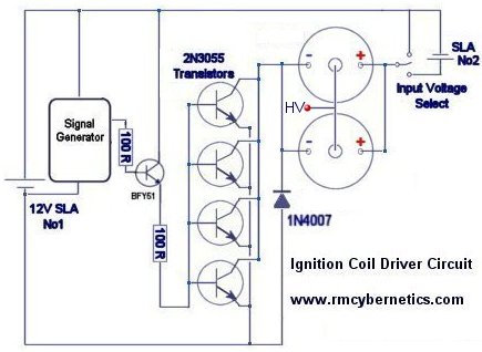
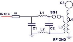
The output from the ignition coils is rectified (converted to DC using diodes) so that it can charge the capacitor bank C1 shown below.
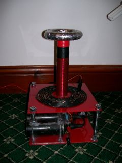
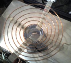 Coils – The primary coil is simply made from 2mm enameled copper wire, wound around a plastic stand. There are six turns in total, but the connection is made at about 4.5 turns when tuned. The secondary coil is wound from 0.4mm enameled copper wire around a plastic drainage pipe.
Safety – Attached to the capacitor is a short circuit switch that is activated by a long plastic handle. This is used to make sure the capacitor is fully discharged, and cannot recharge whilst making any manual adjustments. There is also a switch to isolate power from the ignition coils that is activated using a insulating pull cord.
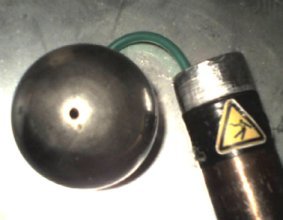 Special Features – This project has several extra features compared to a common Tesla Coil. The topload sphere has a small hole to allow gas to be emitted. A 5mm plastic pipe runs down the inside of the secondary coil, and out of the plastic base.
This allows the gas to be piped in, without interfering with the normal operation of the Tesla Coil.
 Future Developments – This project is currently being upgraded. The new design aims to achieve a higher power throughput. By using more ignition coils in parallel it should be possible to increase the size of the spark gap, or to fire it more rapidly. New ignition coils will used instead of the second hand ones for improved stability. The new design also incorporates voltage and power monitoring features. It also has a neat metal finish and multiple outputs so that it can be used as a multi purpose portable high voltage power supply


Are you ever going to sell secondary coils again?
Yes we will. I do not have a date for when though as we have been working on other things.
What about the polypropylene 1kV 330nF capacitors you used for the capacitor bank? Are they ever coming back, or have the been superseded by the high voltage pulse capacitor?
The HV Pulse capacitor is an alternative yes, but we do still sell the smaller ones.
https://www.rmcybernetics.com/shop/electronic-components/capacitors/polypropylene-capacitor-400v-330nf
You wont get a square wave, especially using a spark gap. Magnetic quenching will help, but the coils will still ring in a sinusoidal way.
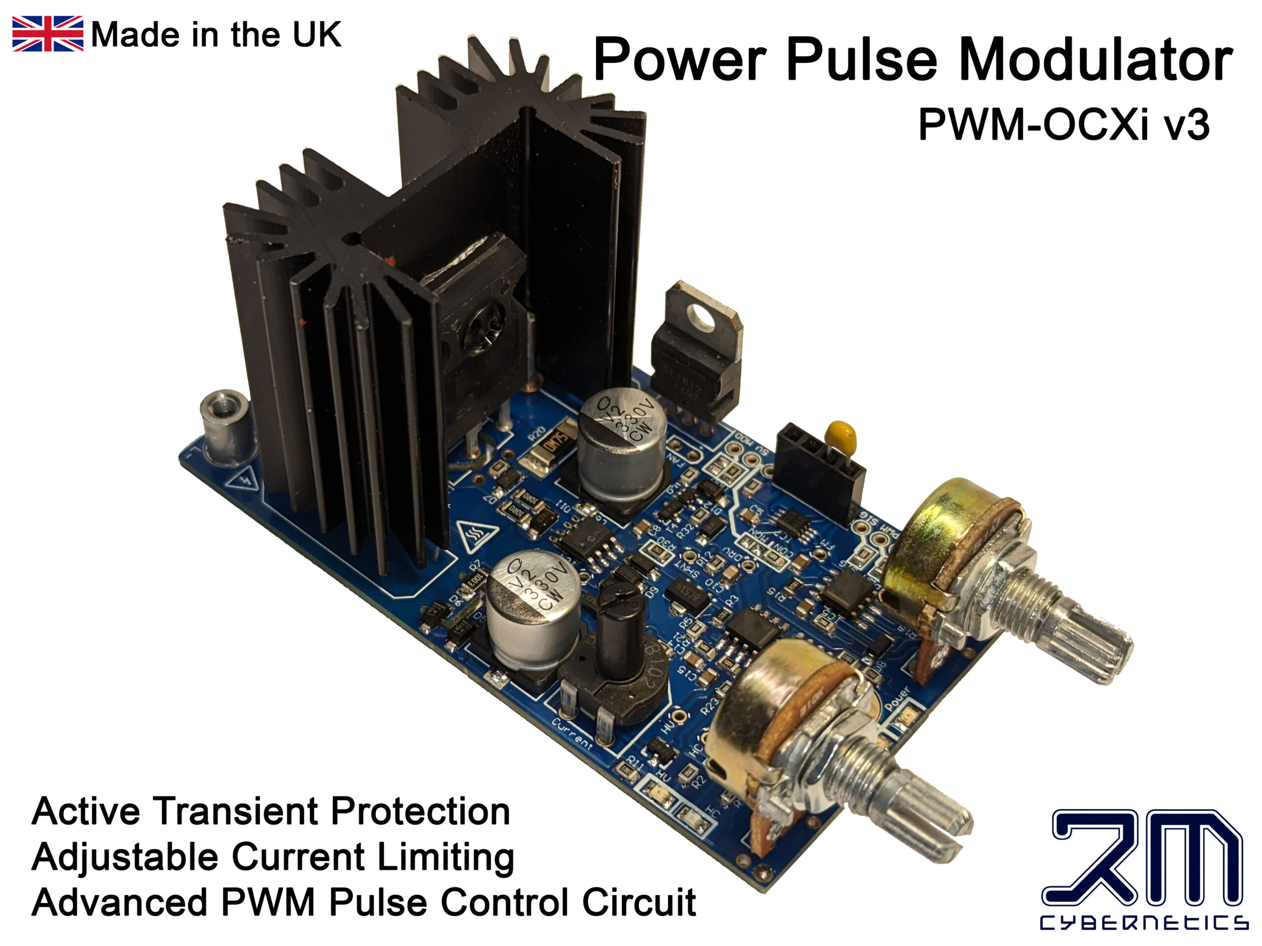
You can use something transistor based such as our PWM-OCXi if you want very fast rise and fall times.
I want to experiment with pulsed DC at various frequencies on a Tesla coil. If I use a battery for power supply, how can I generate a perfect square waveform, sharp rising and falling edges. Would a magnetic field at right angles to the spark gap help?
David, Your diagram in #4765 looks ok.
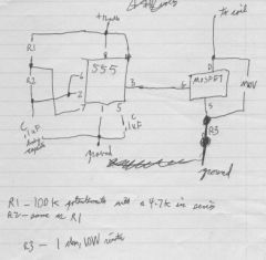
Nicole, No, the resistors etc are needed to make the 555 run.
Jakob, You should add ‘bleeder resistors’ between the terminals. These are very high resistance resistors that will slowly discharge the capacitor when not in use.
How can I safely discharge my capacitors?
Thanks,
Jakob
Is it possible for the NE555 timing chip to act as the signal generator on its own? Do we need the IC socket and other resistors?
like this one?
there’s another tesla coil circuit, will that work?
Yes, but it would be better to remove T1, replace T2 with an IGBT, and connect the signal wire to R1. You must also have a common ground between the signal generator and the coil circuit.
I was wondering, will this circuit from the file works? it was a tesla coil circuit

Building my first tesla coil, using this website, and all is going good… if you don’t include the signal generator. Wiring parts up that only had one or two terminals was easy, but I am not sure what to do with six? Have any circuit diagrams that clearly show what to do with each of the pins? Thanks!
Yes, you can just use 30kV capacitors, and the new coils in our shop will work just fine for it too.
could i just use some 30kV capacitors instead of combining a bunch of little ones, also do the ignition coils have to be old and form a car or can i just get some on this website.
The coil is not likely to get hot, but the arcs will be very hot. If they strike or come close to the coil, you may have problems.
For my secondary coil I am using a material which has a melting point of 60 C [140 F]. Will it be alright?
1. No. Any similar high voltage supply will do. You can use one driver to power multiple coils. You just need to make sure that the combined impedance of the coils is not too low or it would blow the transistor in the drive circuit.
2. The Tesla coil primary and secondary coils do not heat up significantly.
Just a few questions…
1. Do you need an ignition coil driver circuit at all? If so, would you need one for each Ignition coil, or one for both?
2.How hot did the primary and secondary coils get during use?
Thanks
This is the best site for electronics I have ever seen. Great work and information, made easy to understand.
drdreads,
This is fine. See the diagrams for this NST Tesla Coil
TW462,
Yes, you would reverse the diode if you reverse the input voltage. You can email the article to me. The legality of that would vary in different countries, but in most it would be considered as fair use as it is only for reference and not to be posted on the website.
Hi RMC, i have a general question relating to ignition coil set up, i’ve seen some schematics that connect the ignition coil back to front; positive supply connects to the negative terminal, negative supply connects to the positive terminal. I have a question regarding this:
You previously advised me on at least one rectifier on the HV output to charge the cap, would an ignition coil wired up this way produce an output that is more negative than positive and require the diode to be reverse biased?
My question is based on a magazine article that didn’t include any rectification on the HV output, it wouldn’t be a problem to forward the schematic but i’m not sure whether that would cause problems with copyright infringement?
Many thanks
TW
hi thankyou for those answers,i find your site very helpful.just to calrify,do i connect the center tap ground of the nst secondary to the terry filter and rf ground still or will this stop me from getting the 10kv output? and should there be a problem and the safety gap of the terry filter fires will this also put dangerous current through the tesla secondary coil?.thankyou.mark..
Neon sign transformers have a centre tapped secondary coil. The middle of the secondary coil is connected to earth which is normally also the chassis.
To get 10kV you need to disconnect any earth connection and take 10kV from between the output terminals.
While it may work to connect the secondary coil to the primary, I would not recommend it. First of all, this would add extra danger to the output streamers as they would be electrically connected to the primary tank capacitor making them capable of delivering deadly current. It can also create problematic feedback when not precisely tuned which may damage your capacitor or NST.
hi RMC,iv been doing a bit of research whilst waiting for layers of varnish to dry on my new coil and it seems that on a few websites they say it is possible to connect the rf ground to the first turn of the primary coil? supposedly this eliminates the risk of primary strikes,need for a dedicated rf ground and increases efficiency due to the fact that if one uses a strike rail then the streamers are attracted to the strike rail somewhat.is this true and what drawbacks are there to this? i was thinking that this may over voltage some of the charging circuit components.and of course an arc is a conductor,so if the rf ground is connected to the primary then theoreticaly the streamers would carry dangerous charging circuit current in them?.thanks.mark..
hi,i have recently aquired a neon sign transformer for use on my tesla coil.its rated 10kv @ 25ma. on the bottom of the transformer theres a plate that says 5kv-0-5kv. and in between the output wires is a small screw with 2 short pieces of single strand wire wraped around it that have been chopped off,im thinking you are supposed to use a 5kv out and a ground? i have used just the 2 wires and ignored the screw for now and it seems to work.am i getting a full 10kv from doing this?and do i need the ground? this is the first NST ive been able to get my hands on so im not sure how they are supposed to be connected up.thankyou..
Maybe you could add a heat sink to the transistor to keep it cool. You may also want to increase the resistance between it and the larger transistors so that less current flows through it.
no that was kind of an update on what i-m doing but now i have a small problem …i’m useing a bc 139 in the bfy51 place …and it gets very very HOT i got blisters on my thinger from it ….can u give me a suggestion
Erm… Is that a question?
omg… since the last time i tried to make the circuit for the pulse generator and the coil driver …and they do not work …shourly i’m makeing a mistake and i think that my coils are burned out or something vecause i do naot getaround 2 ohmswhen i mesure them
Radu,
The first one is typical of an AC mains powered type. The second one uses DC charging. That said, either would work in either situation, but typically the first one is used as it can cause less stress on the transformer.
TW462,
If you have a scope, you should be able to get a readout through a voltage divider. Ideally your caps and diodes should be rated for at least twice the peak voltage of your supply. Sometimes this is not practical, so they should just be as high as possible. The ignition coils I’ve use will put out 20kV when not loaded. The size of cap you use (combined with the primary coil) will need to have a value so that the resonant frequency matches your secondary coil. If you have a look at the three DIY Tesla Coil projects on this site you can get some idea of the size of capacitor relative to the size of the secondary coil.
Thanks for the response to post 4083, on the understanding that the output will be a voltage spike rather than a regular wave, am i going to be unable to measure the output reliably through a voltage divide? If not is there any chance you could offer some guidance on cap values? As it stands i believed a combined rating of at least 20kv should be enough, capacitance of 1.5 to 2nF? Does that seem a reasonable starting point?
that one and this one …. i do not know how to put 2 images on the same post
Have a look around your local DIY store. Maybe a door handle or metal lamp shade would be a good top.
I’m not sure which two diagrams you mean. There’s a lot of different ways you can make a Tesla Coil.
Hello, my name is Radu I’m from Romania and I stumbled across your site some years ago and I never managed to start a tesla coil project of my own. But now I finished collage and I have some free time to spear until now I made a peaty good stand and the coil for the secondary, I’m sorry I do not have a camera right nou to put some pictures. I’ll make it around 12 inch tall with a toroid on top, until now I do not know what to use fore a toroid, a aluminum duct is too big for my 2 inch diameter secondary …
I researched the tesla sites and I’ve came across 2 diagrams and I was wandering if you could tell me the difference between them. I’ll make the wiring like on your site because I’m using tow ignition coils, just like in your diagram.
Thank you, Radu.
An ignition coil works quite differently to an AC transformer like those equations are for. The output of them is a high voltage spike rather than a continuous sine waveform.
Also those equations are meant for charging a capacitor every half cycle so no diodes are needed. With an ignition coil system you must use at least one diode.
If your output voltages and currents are unknown, you are just going to have to determine the best capacitor by experimentation. You will also find that certain frequencies will work best when they match your spark gap firing rate.
I was just reading advice on choosing capacitance values for the capacitor bank and am trying to see how it ties in with an ignition coil driven design. The formula i was looking at required the supply impedance and line frequency; the formula to calculate the supply impedance required output voltage and current of the supply. Now, i understand the equations and that they are only a guideline, but where do you start if you’re using an ignition coil that will produce unknown voltage and current? Also the supply to the coil has a variable frequency, doesn’t this complicate things further? I’ve looked at several similar designs and capacitance averages to approx 3nF between them, i could experiment with this but i have budget restrictions on my project and need to justify my choices. Any guidance would be very welcome, thanks.
While the average output current of the coils is likely to be less than 10mA, they may have a much higher peak current due to the pulse nature of the output. To be on the safe side, I would use the 100mA type as it would save you from possibly having to replace blown diodes later on.
Would just like to say a big thank you for all the information you’ve provided so far, it’s been a really big help. I’m currently developing a system for a college project, 555IC frequency control to a single ignition coil, only difference being the coils are mounted axially and output between 2 electrodes to keep the arc where i want it. Something that i hadn’t considered was the HV rectifier diode between ignition coil and mmc, i was looking at the 20kv diodes in your shop, would the 10ma be suitable or should i consider the 100ma?
Check out our latest Tesla coil Project
Blowing these indicates that there are large voltage spikes on your PSU. Use zener diodes or MOVs across your coil and PSU terminals to limit voltage. SP1 is a MOV. Contact us by email about the diagram.
Hi RM,
I am using the PWM-OC10A I bought, to drive a toroid transformer in open collector mode. It still blew the 555timerIC, LM393 and the 1N4007 diode and the track for the diode.
I am in repair mode now. What is the SP1 component? Also can I get an exact cct diagram to repair it?
Deven
A medium strength field
HOW MUCH STRENGTH MAGNETIC FIELD IS SETUP BY A MEDIUM SIZE TESLA COIL
The airflow from a VDG would not be powerful. It could be possible to partially control a discharge in this way.
can a van de graff generator be used to charge up a powerful flow of air,
and this air stream be made to carry teslabolts ?
if this can be done it will be a true trsla coil gun
Yes, You can use the HV output to charge the tank capacitor.
Can you use Air purifier/negative ion generators to make Tesla coils or power them ive been told u can just need to clarify and a bit of a explanation on the process to utilise them if so
Hi am i able to use the plasma balls that respond to touch and sound for parts to make Tesla related technology there’s a HV transformer int he 2 i have that run off 4AAA batteries and excite the sealed electrode in the plasma ball to generate the effect i figured i might just have all the stuff right in those two plasma balls to make mini telsla coils and power them off aaa batteries 🙂
so I got a thick pusing arc across the spark gap by putting more bottles in. uafortunatley, my secondary was put on hold so I have turned to my sstc. I want to know, would a modified joule theif circuit be an adequit inturupter?
Type your message here
TO JERRY: see coomments No. 3047 and 3075. You do not need groundng at all with bipolar TC.
aldrin,
So many diodes in series is not likely to work. They wont switch at exactly the same time so some are likely to be blown.
That transistor is fine.
JOSEF,
Yes that is correct. The capacitance would be 150nf/12 = 12.5nF
Jerry,
If you are unable to run a wire down the outside of your building to a rod in the earth, there is still an alternative. You can place a wire mesh over the floor under and around your TC. It should be at least several meters wide.
arccrazy,
Seems like your capacitor does not have enough capacitance. Are you sure you have constructed and wired them correctly?
OK so now i have removed the center point ground. I have the transformer in a plastic box and a pvc pipe to turn it on. I am getting closer but not quite there yet. the sparks are either thick white like the ones strait from the transformer, or thin purple ones that dont happen continuisly
How to test ground ?
My studio is located on third floor. I can’t use ground rode or water pipe (because my audio/video equipment dont like it) to discharg spark for change light texture. For now I use long copper wire that I leave on the floor..at the other end of wire (near tesla) I plugged small rode (in my hand) .
Before I try to plug it on outside fence and I never got shock but now in my studio with long copper wire yes ; )
Someone have solution ? or how Can I test ground ?
Merci!
Type your message here:
See please my comment No.3047 (28th Aug 08).Bipolar twin TC and also horizontal TC work very well.Here is the question re TOTAL VOLTAGE TOLERANCE : I am using 12 polypropylene caps in series. Each is 150 nF and rated up to 2000 Vdc(500 Vac). I believe that total V tolerance = 12×2000 V = 24000 V. Cornell Dubilier caps. 942C20P 15K are not cheap, so I would be grateful if you check my assessment re total V tolerance of my caps all wired in series.
can i use transistor IRFP250? thank you
i dont have high voltage diode. can i use 20 pcs of 1n4007 in series? to make a 20KV diode? any suggestion? TIA
An NST is wired a little differently to an equivalent lower voltage transformer. You need to change how you use it. The middle of the secondary coil and the metal core are grounded (connected to the earth cable). You can get an arc between one of the outputs and the earth connection but it will be just 4.5kV. If you want the full 9kV you need to disconnect the earth wire from the transformer.
Note that this is potentially dangerous as the once earthed metal body or brackets are now floating at a dangerously high voltage. You should make sure to put it in a new case to prevent accidentally touching it.
Hi. I need help with y tesla coil’s charging circuit. I have a neon sing transformer at 9 kv and 60 ma. I do not have a rectifier. I can’t get any arc to happen over the spark gap. my capacitor is two wine bottles. It has a gfi but the indicator isn’t going. why? ( the cap is acros the nst.)
aldrin,
The diameter just needs to be big enough to take the current you want to pass. Bigger than that would make no noticable difference.
Deven,
No. They are PNP type, this circuit is for NPN.
Hi,
I have a heap of MJ2955’s. I wonder if I could use them instead of the 2N3055’s for the coil driver.
Thanks
deven
okie thank you. can i use 1/4 inch copper tubing on primary coil? bigger diameter of primary coil can maximixe the output voltage of secondary coil? TIA
Rotary spark gaps are better because they give better quenching
which is better? rotary space gap or ordinary space gap?
OK thanks, I’ll ask him. but i’v been having troubles with my tesla coil.
I have a sgtc with the cap in parralel to the power source. I have a secondary of aporx. 900 turns and a variable spark gap. my power source is a zvs+flyback config. I can onlty get minor puple sparks coming out of the top and none with a topload. (I have tried many toploads) I think I even have the coils tuned.
TESLA CIRCUIT,
I don’t know becasue the important parts are not even labeled.
aldrin,
Non-polar, high current or pulse discharge types. Definatley not electrolyitic, they will explode! Ones made from rolled metal and polypropelene are good. Ceramic ones will also do for small Tesla coils.
what kind of capacitor is use on MMC? polar or non polar? electrolitic or not?
My frein gave me this circuit and claimed it had worked before. I was wondering if you think it would work?
I have limited resources and I dont want to build it if it wont work.
Thanks
Microwave oven diodes are only rated for a few kV. you would need ones rated for at least 20kV. Full bridge is best.
Hey,
I recently received several microwave oven diodes. I was wondering if they would be sufficient to rectify the output of two anti-parralel ignition coils.
Also, how do you wire up your rectifier?
Is if Full or Half bridge?
thanks
Jerry:
I would recommend you just build your own. It’s the most fun way I know!
Yes, you may have to do a little research first, but trust me, it is well worth it!!
You can find most of the information you will need on this site– right under your nose!
Good luck, and HAVE FUN!!!!!
Hi, someone can tell me where I can buy one ? (Tesla coil, assembled or not) It’s easy way I know !
Thank’s for all information !!
a nice simple driver is a ballast circuit to drive a ignition coil its output is very similar to a neon transformer for those making tesla coils
Yes it is very dangerous. A simple mistake could lead to immediate death.
Start small, make a battery operated Tesla coil so that the power levels are limited to non lethal levels. Please don’t mess with mains powered high voltage transformers.
attempting to make a tesla coil using a neon sign transformer with an output of 15kv at 30mA i have no experience with electronics of any kind whatsoever. is this dangerous and what should i do/not do?
Yes.
Do you think a zvs driver+ large flyback could ower this coil?
There are many ways to build a solid state Tesla coil. You really need to research the varieties before continuing.
I am looking to build a solid state tesla coil. I have a igbt rated 1200 volts at 600 amps. Could i use this to power a miniature coil? If so would it work with a ne555 circuit? I dont know how many windings but i assume the 555 circuit would be tunable enough.
Ryan,
1100 turns sounds like a lot for something just 35 cm tall. several hundred should be enough. Having so many turns mus mean your wire is very thin. Thin wire has more resistance and lowers the Q factor of the coil making it waste energy.
When you build a coil you must tune it otherwise you will get nothing. Read through the messages on this site for help on that.
Is your secondary coil connected to an RF ground? This can make a big difference on most coils.
Here is one of my videos of Mini Max. It’s short (only 23 seconds or so) but it should give you an idea. As a topload, I have a 1 inch diameter steel ball bearing.
Hi, I just finished building a coil. Its got about 1100 turns of thin copper wire on a PVC pipe thats 14 inches high and about 7 turns of copper tubing for the primary (pancake type). The spark gap is made of 2 adjustable bolts. Cap is a bank- made up of 10 x 2kv 47nf ceramic disk type caps. Whole thing is powered by a 9Kv 30ma NST. Everything is hooked up and when i turn it on, the gap fires but no sparks from Toroid. Would be really greatful for some help. What am I doing wrong here? I tried holding a wire connected to the bottom end of the secondary close to the torroid. But still no sparks or Corona.
Woops! sorry. the pictures didn’t come through. Here are a couple of pictures of Mini-Max while it’s running. More to come!
Der Strom
Glad to hear of your success. If you want to post a video. Uplaod it to somewhere like youtube, then post the link in your message. The moderator will embed the video into your message.
This is it! Mini Max, my ultra-tiny tesla coil! I was planning on posting pictures of Max, my mini tesla coil that I described a little while ago, but Mini Max performed much better. It is a small cardboard tube wound with roughly 300 turns of ~28 AWG wire that I pulled out of an old motor. It uses my 9 kv, 60 mA NST with a single beer bottle capacitor giving a capacitance of only about 0.7 nF. Mini Max produces an estimated 100 kV from the 9 kV input. I will post more pictures and possibly a video (if it is permitted) of Mini Max’s performance. Unfortunately, the electric field from this tiny tesla coil is so large that it sets off my answering machine and my smoke alarms if I run it too close.
Thanks for all of your help!
Sincerely,
Der Strom
jango,
Yes, RC1 is useful in any ignitioncoil application to snub spikes.
Yes you can connect directly. The number of turns depends upon the voltage and frequency and duty. You just need to make sure that the current draw does not exceed the ratings of the PWM-OC10A
John-Paul,
Wow, that is quite an extreme version of a battery powered TC. Try placing a MOV or TVS (rated for some voltage below the rating of your transistors) between the C and E of each transistor, or between the inputs of each coil. Note that they heat up as they absorb over voltage, so keep an eye on them. Not sure what you mean by a ‘cap soft start’
Der Strom,
Just google for “Comparator test circuit” or something similar.
jango,
Yes, RC1 is useful in any ignitioncoil application to snub spikes.
Yes you can connect directly. The number of turns depends upon the voltage and frequency and duty. You just need to make sure that the current draw does not exceed the ratings of the PWM-OC10A
Then I of left PWM6OC10A to connect a flyback directly? How much turns of copper wire have I to roll up (12? 30?) Thanks
Hello. Then I to directly connect a flyback and a PWM OC10A. Thanks
I just put together the circuit you posted (thanks, by the way) but I’m not getting any output from either of the 393s that I have. I am getting an output from my 555, but nothing from my 393. I’m sure at least one of them isn’t burned out. Do you know what might be wrong? Is there a way I can test it?
Thanks a lot for your patience!
Sincerely,
Der Strom
Hi I am almost ready to test my coil that is based around your batt powered twin ignition coil setup. I am useing 2x 100amp 12v car batterys 20x 2n3055s on a cooling bridge, a low inertia RSG with speed control and 30kv cap, as well as a load of 30kv diodes for the pararelled 8 to 12 igniton coils. the tesla coil is for my art degree in the final uni show and i wanted to use a large amount of ignition coils for the asetic but I am haveing lots of problems with feedback destroying the tranistors. I would also like to create a cap soft start from the 2 batss but not sure what the values would need to be. Can you help me with some sort of feedback prevention circuit as well as help with the soft start caps… thank-you this site rocks!!!
For this diagram is necessary it to include system (R-C1) between the D1 diode and the ignitions coils to avoid a tension of breakdown? thanks
T1 would be your array of 2n3055’s or other transistors
WHOA!!! Thank you sooo much for pointing that out! That’s probably why another circuit I’ve used isn’t working very well.
How is your circuit connected (I assume you are using the power pulse generator with PWM and the ignition coil driver that you showed at the top of this page)?
Thanks, once again for pointing out the incorrect connections!
Sincerely,
Der Strom
We don’t sell either of those items. You can get them from most electronics stores.
(1) where could I buy, on your site the radiator for 4 transistors 2n3055 (2) the diode is it special see 1917 DER STROM thanks so much
der strom,
You should not connect your PSU in series with the load. You should link the grounds (0V) of the PSU’s , then connect the +ve of your load to the V+ of your high current PSU instead of the other.
The current drawn is dependant upon ohms law. The impedance of your load limits this current. Even if you PSU was rated for a million amps, it would still only supply 1.7A.
The second diagram wont work. The way you add T2 is all wrong, so is the way you connect the second power supply.
Jango,
Not really sure what you are asking.
then I to transform an amp-mêtre (1_5 A) in volt-mêtre (10kv -50kv) or in frequency-mêtre to test a PWM. thank you and better greetings
Sorry, forgot to post this.
Would this circuit work, or am I missing a few key components (it’s a combination of your power pulse generator and the paralleled ignition coil driver)?
Thanks!
-Der Strom
I finally got hold of a 15 volt, 5 amp power supply (also for a computer) and connected it in series with the “load” shown on the circuit, but the flyback transformer is only drawing 1.7 Amps from the 5 amps supply. Do you know why this might happen? I was wondering if I should just add in another transistor to switch the power supply instead of just connecting it in series with the load. That way I assume I’d lose less power.
Those equations are typically designed for side wave AC power from mains, so if you are not powering it like this, the result will be invalid.
If you use a diode, you should calculate the RC time constant to charge your capacitor to the voltage you want. i.e. You can find what capacitance will charge to the voltage you want in that time.
Thought I might mention:
I tried running my tesla coil without a high voltage diode after the ignition coil and, using a single beer bottle capacitor, I got faint streamers to air about 3 cm long. I just connected the circuit like the ignition coil was an NST, and it still worked. I assume, though, that since it wasn’t DC, and the capacitor charged every half-cycle of the ~20khz output of the ignition coil, the capacitor was unable to charge fully. Because of this, I could not have a very wide spark gap, and therefore, I did not have a good output from my TC.
I plan on getting a bigger, better heat sink and possibly a battery-powered fan that I can just “plug in” to my solderless breadboard that I currently have the circuit on, directed straight at the MOSFET to keep it cool (or cool-ER).
By the way, I used the equation on deepfriedneon.com for the capacitor/transformer match, and after filling in the equation with my own information (i.e. a different frequency other than the 50/60hz.), it said I would need a tank capacitor with a capacitance of 69nF. Does this make sense? My flyback transformer delivers about 15kv at about 15mA (maybe as much as 20mA).
Thanks a lot!
-Der Strom
jango,
Yes a pwm is ideal. No you cant use a spark-gap (eclateur) instead of RC1. Please use the translator I mentioned to you before.
der strom,
Glad you like it. Keep an eye on the temperature of the heatsink if you are going at 5A.
Oh, by the way, your Power Pulse Modulator works GREAT with my flyback transformer. Even with only 1.1 Amps of input voltage, I get nice, long, HOT arcs that I can draw out to about 3 cm! I can’t wait to see what it does with 5 Amps of current!
Oh, I forgot to mention that I’m no longer using the transformer driver that I posted above. Now I’m using your power pulse modulator with my wall adaptor power source in series with the flyback. It works GREAT!!!
Sincerely,
Der Strom
in his message 1940 DER STROM show a schema can i replace RC1 by a “”eclateur “” may be a sparker to avoid overcurent
thanks
i read that write DER STROM bout tesla coil it is a lot of very goods things
i d’nt find if he use a PWM OC10A
for drive ignition coils
in a schema see in ” diy tesla coil ” may i use a PWM as signal generator
thanks
sorry my ENGLISH is a broken english
I have found on various other web sites schematics of a DC Tesla coil that include a 20mH charging choke between the HVDC power source and the tank capacitor. Would this improve the output of the tesla coil?
No, 1.1A is very low. About 5A or more would be best.
Right now, It is running off of an 18 Volt, 1.1 A wall adapter for an old printer. I’m not sure if it is taking the full power, though. If it is, is 1.1 A enough?
How many amps is it drawing from your battery when it is running?
MY FIRST WORKING TESLA COIL!!!!!
Within a couple of days, I took the wire from an old MO fan and wound it around a cardboard (didn’t have any plastic) tube and got about 650 turns. For my primary transformer, I used a flyback transformer and the driver shown above, taken from somewhere on michaelv.org. Since the flyback already has a built-in rectifying diode, I did not need the 16kv, 300mA diode I found in another MO. I plan to use this with my ignition coil. For my primary coil, I used 7 turns of 3mm diameter stripped copper wire, tapped at about 5 turns, mounted on 4 cardboard supports in a steep conical shape. I used 3 beer bottle capacitors, giving me a capacitance of about 2.5nF. For the topload, I used an 8cm (yes, centimeter) diameter aluminum pie plate flipped upside-down. Right now, I am getting 5 cm streamers to air (only visible in extremely low light), but only 1 cm sparks to grounded screwdriver. I was wondering if you knew why I’m getting such small sparks to the grounded screwdriver. I’m sure it is a good ground connection. Thanks for your help, as always!
Sincerely,
Der Strom
Yes, that is plenty. Matching the freqencies is more important.
I’m not sure if you ever answered my question in post #3103 on this page. I also just realized that with thinner wire, I would have gotten MORE turns. So my calculations must have been off. Do you think 700 turns would be enough, since it uses resonance rather than the turns ratio?
Thanks!
Zensunni,
There are many such example on the net allready. I would reccomend googling for NST tesla coils.
tesla fire,
Yes. The thickness of the wire depends upon the amount of current you want to pass through it. it is bes to be too thick than too thin. Copper pipe is a common choice.
can polyester sheets be used to make capacitors?
what wire can be used to make primary coil? what is the minimum awg value of the wire for this application?
I am seeing alot of flybacks diagrams as a power supply however I am going to use a 9k nst@.03ma. What would be the best set up? and if possible please include a diagram. thank you very much for any help.
909,
A capacitor stores energy not charge, you will need a diode unless you discahrge it betweemn each half cycle of the AC current
IF DR TESLA WAS ALIVE TODAY HE MOST CERTAINLY WOULD HAVE BEEN PROUD OF YOUR EFFORTS.
can a step up transformer be used to store charge in a high voltage capacitor? will i have to use high voltage diode?
Thanks
Great advice
awesome site!!
You should have a large space between the primary coil and your metal case. The oscillations in the coils will induce eddy currents into the metal case which would waste energy as heat.
It looks like you have a lot of primary turns. It might be better to use less turns and with thicker wire. You would have to increace the capacitance of yout tank capacitor to compensate and allow it to run at the sme resonant frequency.
Also make sure all high voltage parts (such as the capacitor terminals and flyback lead are kept short and well insulated. You could insulate any bare HV metal using thick epoxy.
Here is a pic of the schematic, for the previous comment.
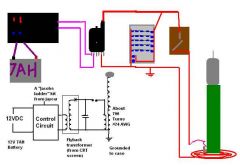
Here is my tesla coil.
It is currently running off a 12V 7AH battery that is about 2 years old.
It is powering a CRT flyback from a TV, which has an internal diode in tact.
The cap bank is made of:
6 paralell strings of 5x3KV caps in series. Their capacitance varies.
There are 2 30KV 1nf caps in parralell with the first caps.
The spark gap is simply 2 metal rods put close to each other that can be adjusted. It works well.
All of these components are mounted in a metal computer case. This is ground for the secondary and the -0v of the primary coil.
The computer case is ventilated with the original fan, connected to a 9V battery inside the case, with a switch mounted on the case.
The primary coil sits on the case, and has a tapping clip to connect it to a tapping point on the coil. It is currently tapped at 3.3 turns.
The output is 1.3 cm plasma to air, and 7cm sparks to screwdriver running off a 12V power supply (from 240V mains). I understand that this is unsafe, but the battery gives about 3/4 of that output.
How can i increase output or improve design? Thanks
instead of using cylinder ignition coils try using the ones that they use on v6 engines they put out 25000volts at ruffly 5 amps.
Very low. In the microamps range.
what is the amount of current in secondary coil during discharge?
black bird,
No, the voltage output is not proportional to the number of turns. There isn’t really a minimum current, it would depend on what you are trying to do, more current, more sparks.
Anyone knows if the altra scienza works?
I used to download pdfs from emule … but it seems that it stoped … anyone knows ? … or some other like this?
Very good about Alternate energy with Tesla and free energy 😉
what is the minimum current required as input to drive tesla coil if we can ignore voltage?
in the above shown apparatus “Secondary Turns is 850”. is increasing the secondary turn to 3000 going to help me to get higher voltage? is there a limit to the number of turn in secondary?
After wiring my 2-foot secondary coil, I realized that I had slightly thinner wire than I had wanted. Because of this change in wire diameter, my secondary ended up with roughly 700 turns rather than the 900 that I had calculated. Do you think my tesla coil might still work, or will I have to redo my secondary coil?
I appreciate all of your help and patience with all of my “somewhat dumb” questions, and I want you to know that you have helped me a great deal with my journey to understanding high voltage electronics.
Once again, thank you soooo much for all of your help, and KEEP UP THE GOOD WORK!!!
sincerely,
Der Strom
Not really, You would need a physically larger device and components for higher power levels.
is it possible to acquire mega volt spark using the same setup shown above?
what should be changed for output of 10^6 volt?
Series, add voltage. Parallel, add current
what will be the output current and output voltage compared to input current and input voltage if i connect transformers in
(a)series
(b)parallel?
IT takes mains input of 220V and gives two 6V outputs. This is a step down transformer. You can connect as many as you like in parallel.
what does “I/P 220V~50Hz
O/P 6V x 2 600 mA” means?
i found it written on a transformer.
how do u connect transformers in parallel?
how many step up transformers can i connect in parallel and still get spark?
HORIZONTAL BIPOLAR TC powered by battery
With bipolar TCs RF grounding is not necessary, because the second half of a bipolar has about the same function as the ground in a typical vertical TC (consequence of symmetry). The horizontal bipo is electrically similar to the twin (see No. 3047). The geometry is different. There are not two vertical secondary + prim. coils but only one continuous-wound secondary mounted horizontally with the primary mounted over the center of the secondary coil. The center of a primary winding is marked 0 with an equal number of turns each side of center. The tuning is done from the center of the primary by an equal number of turns each side of center marked 0. The voltage rises to a maximum at the ends of the secondary c. where the sideloads with the “rabbit ears” are. The sparks travels between them.
My favourite horizontal bipo – in nutshell :12-24V battery / sq.w. oscillator 555+393 /
4 x 2N3055 / two ignition car cs.-antiparallel / HV diode = 60 x 1N4007 in the tube filled with mineral oil / SG=copper tubes+fan=3 x 2mm gaps / primary cap. 7.9nF /
Secondary: PVC tube 60mm OD, 950 turns of 0.33mm(28awg). Sideloads: tin biscuit circular containers 19cm x 10cm. “Rabbit ears”: 2-3mm wire, well insulated by vinyl tubing to eradicate corona. Primary: helical, PVC tube 160mm OD,
8 turns-0-8 turns of insulated HiFi flat cable (8awg). Taps: 4t.-0-4t.
Performance: up to 22-23cm (24V bat.) and 18-19cm (12V bat.).
Yes, You can use a rotary spark gap for high voltages, or a magnetic interrupter (commutator) for low voltage.
Well this is probably a stupid question (i look pretty dumb in the company of someof the people here). I have been experimenting with huge layden capacitors and electrostaics for years .Im am very interested in making a tesla coil in its simplest form. Can you tell me is it possible instead of using Electronic ignition coil driver circuit can i use mechanical means to generate the pulse (as in old fashioned car distributor points)..?
BIPOLAR HORIZONTAL AND TWIN BIPOLAR TCs
I have been inspired by this excellent web pages to do experiments with small TCs. However I am making not vertical TC but bipolar horizontal and twin TCs only. They are efficient and portable because there is no need for any Rf ground. Providing that you choose right coupling and tune precisely, all racing sparks should be eradicated.
Best performing is TWIN BIPOLAR – in nutshell:
12 – 24V battery/ sq.w. oscillator 555+393/8x2N3055/ two ign.car cs. antiparallel/ HV diode=80x1N4007 in the tube filled with mineral oil/ SG=copper tubes+fan=3x2mm gaps/ primary cap. 12.5nF./
Twin TCs: Secondary=70mm OD, 850 turns of 0.33mm(28awg). Both coils were made identical as best is possible, wound in the same direction. Toploads: tin circular containers 19cm x 10cm and you get as a bonus Danish biscuits. Primary: helical 20cm OD,
8 turns of insulated HiFi flat cable (8awg). You can wind primaries either in the same or in opposite directions.Taps at 5 turns on each coil. If you wound primaries in opposite dir., you have to tap only one primary coil at the beginning and at the end of winding (1 and 8 turns).
Performance: 27cm streamers (24V). You can get thicker streamers by using of four toploads in the “double-decker” arrangement and retuning. Providing that all four identical toploads have sparking tips you can get double, parallel, horizontal streamers.
Just few cm at a guess.
what distance would you suggest for my tesla coil (4 inch secondary diameter, input power of 540 watts)?
10cm (~4 inches) does seem a bit far unless the input power is very high. Closest point was about 2cm in the coil shown here.
It’s me again. I’ve pretty much finished with my 4-inch-diameter-secondary tesla coil, but I am having trouble getting it running. I know I have roughly the right capacitance, pretty sure that I have a good ground connection (3 foot piece of steel pounded into the ground), and a good transformer (that matches the tank capacitor), but I am not getting the slightest bit of corona out of the topload. I was wondering if it was a problem with the coupling (my primary coil is a conical primary at roughly a 10-20 degree angle), because the very bottom of my secondary coil is about 3 1/2 inches-4 inches from the primary. Is this too much? I plan on chopping off the extra pipe at the bottom of my secondary coil to bring it closer to the primary. I also plan, if I absolutely need to, on winding a new primary. What do you think the problem is? Could it be the coupling? Thanks again!!
Sincerely,
Der Strom
No, Usually a wider coil is reccomended. It was actually 5cm wide, (I just updated the table at the top). I chose this width just because it is the size of pipe I had available at the time.
Wider is often bettter, but you have to have it tall enough so that the output isn’t to close to the bottom end. You could probably get a similar output from a coil that is half as tall and twice as wide.
I noticed your secondary is only about 3cm wide. Does having a thinner secondary make the output stronger? Why did you choose this width?
der strom,
An op amp requires 2 connections for power which are usually marked something like Vcc and Vee (Vcc is +ve). The two inputs are for a signal and will take a positive or negative input. If you make the non inverted input go high, the output will also go high, but if you make inverted input go high, the output will go low. The comparator compares the voltage on the inputs and determines if the output should be high or low.
I’ve had some success in building the ignition powered coil, just like to share a few tips for anyone thinking of building one. After wiring it all up I got big flash overs on the rectifying diodes so I used resin (from making GRP panels) to ‘pot’ the diodes and I also used heatshrink on the connections. This stopped the flashovers and the spark gap was then firing well – but nothing from the topload after a lot of tuning! The only thing left was a trying a better RF earth (i’d just been sticking the wire from the secondary in some damp earth). So I got a 10mm dia ally rod, stuck that in damp ground and jammed the RF earth wire onto it. Tried it out and got plenty of sparks from the topload. So, couple of things to try there.
I did a Google search for the IC mentioned in my post number 1852 (BA6993) and found out that it is a dual comparator. One of my other projects uses a dual comparator (like an LM393), but the datasheet says that pins 2 and 6 are “INV.INPUT1″ and INV.INPUT2”, and pins 3 and5 are “NON-INV.INPUT1” and “NON-INV.INPUT2”. I know that the “INV” means “inverse,” but I am a little confused about which one means positive and negative: “INV” or “NON-INV”? Thank you so much for your help, and I’m sorry if this is in the wrong category for the question.
what would happen if a lightning bolt fell on a tesla-trooper
I would suggest trying different capacitance values for your tank capacitor as it is probably simpler than making a new primary coil. If you capacitor is made from several in parallel, try just using one and trying different tapping points, then two, and so on.
Ok, I have cut the secondary down to 40cm, and tried different numbers of primary coil windings, but i have still acheived the same result; wirey sparks to a grounded object. do i need to dramatically increase or decrease the number of primary coil windings? as i am using the same tappable primary coil. thanks
I did the exact same thing with this coil when I first put it together. I just got a hacksaw and cut it down to 40cm. If you are careful, you will only damage the windings right where you cut, you can then unwind a few turns and tidy it up again.
What size would you reccomend?
Thanks, great site!!
Here is my tesla coil secondary, shown next to a 12 inch ruler. Is there any way I can change the size of this coil without damaging the remanding windings?
Yes, it sounds like it is too long and thin. Make it shorter and re-tune it.
My 12v SLA battery powered tesla coil is giving weak sparks,in the dark the output is a few feint streamers about 4mm long. It is very similar to your design, but the secondary is about 7cm x 70cm. Could having such a large secondary coil make the output too weak? Do i need to make my secondary smaller?
Thanks for your help
I HAVE READ ABOUT TESLA COILS IN YOUR WEBSITE AND THE INTERNET. I WANT TO KNOW HOW DR TESLA USED A TESLA COIL IN WARDENCLYFFE TO TRANSMITT ELECTRICITY CURRENT WIRELESSLY.
IF DR TESLA COULD DO IT USING THEN YEARS TECHNOLOGY , IS IT POSSIBLE TO BUILD ONE TODAY,?
produc this HV voltage dubler DC high voltage.
3mm should be fine for making it work.
I’m sorry, I must have the wrong number gauge. This wire is roughly 3mm. thick (without coating). Maybe it’s 12 AWG. But anyway, would 3mm. diameter wire work for a tesla coil, or wil it (again) have too high of a resistance? Sorry about the wrong size.
Der Strom
I think 1mm diameter wire (18 AWG) is a bit too small. The resistance of such a length of thin wire would lower the ‘Q’ factor of the system and dampen oscillations. If this is the thickest wire you have, you could take four lengths, put the ends in a clamp, then twist the wole lot to form one thicker wire. I find a hand drill is useful for doing this sort of thing.
After some more calculations (which I hope I don’t have to follow exactly, like you said), I found out that my tesla coil needed a primary coil wound with wire or pipe that is at least 1/4 inch diameter. However, since I didn’t have any, I just used standard 18 AWG house wire (stripped). Do you think this will still work, or will there be too much resistance?
As of now, my tesla coil still isn’t working, and I am wondering if that is the reason. Thank you!
Skappy,
Any Bipolar, NPN transistor rated for about 1A will do.
der strom,
Don’t rely on your calculations. You will always need to tune your TC after it is constructed as there are many factors the calculations don’t consider. You should make your primary coil longer (more turns) than you calculated for and make it using uninsulated metal so that you can adjust the effective number of turns.
That is what I figured, but I thought I would ask just to make sure. In my calculations, I figured out that I would need 14-15 primary turns with a completely vertical helical primary coil. After measuring out all of the wire, however, I switched from a vertical primary to a conical primary, and I only got about 11 turns. would this be enough, or should I measure out more wire and re-wind the primary coil?
Hi,
I encounter difficulties in finding a BFY51 transistor. May i ask you others reference which could do the same job ?
Thank you very much
More turns. Think of it in terms of a place to store energy. I you can store less in your capacitor, then you can use more tuns instead to store it in the magnetic field.
This only works practiaclly to a certain extent because more turns means more inductance which equals more reactance against the flow of changing current. it should not be a problem as long as your number of turns is less than around 20.
N3rD:
I have an ignition transformer very much like the one you describe, and it it used to ignite the fuel in an oil-burning furnace. Yes, the output is AC.
RMCybernetics:
If my tesla coil capacitor has a slightly smaller capacitance than I really need, would I make up for it by tuning the primary coil to greater or fewer turns?
My 4-inch diameter secondary Tesla coil is almost finished!!! I just need this last bit of information. Thanks!!!
N3rD,
I would think the output is AC.
Anyway, a transformer needs an AC input so putting a rectifier before its input will prevent it from working. if you want a DC output you would put a high voltage rectifier on its output.
before i forgot, the coil was suspended in the solvent for a couple of hours, to let the solvent diffuse into the coils
YES! I finally have a economical approach to get a lot of enameled wire from the lamp choke! I suspended the hard coil(don’t know why,maybe it is glued together) into a little of industrial solvent(60% aromatic hydrocarbons,30% ketones , 10% alcohol),and the coil become soft and loosens, and it was ready to use!
Hello,
I am currently starting work on a small tesla coil (4 inch secondary). I found an ignition transformer on Ebay that uses a 120VAC standad wall input and has a 10kV, 23 mA output. I am awaiting a response from the seller to see if the output is AC or DC. It could be either because it is in an enclosure similar to an older NST, so there could be more in there than just the transformer. If it turns out to be DC ouput, do I need the driver circuit? Also, if it turns out to be AC, could I put a bridge rectifier in between the wall plug and the primary?
Thanks so much!
Yes
Is it possible to put two TV flybacks is parallel to acheive a greater charging current?[then using it for a power supply]
Thanx
How do you “tune” the Tesla Coil?
Clean hands, a bottle of cyonacrilate (super glue), some tape, patience.
Start by taping the end of the wire to your secondary former. Put the reel of wire on a roller like a pen in a clamp.
Try to keep the wire tight at all times to prevent it unraveling. Turn the former with one hand while using a finger or thumb of the other hand to press the wire onto it. Push the wire against each previous turn so that he whole thing stays tight.
Every so often put a tiny spot of glue so that it wont unwind too far if you slip or drop it.
Thanks.
Do you have any suggestions on how to wind the secondary coil? I just want to know before i start.
Attached is a photo of my priary circuit. The Ice-cream container on the right is the HV filter, the PVC tube in the middle is the secondary coil(unwound) at the front is the Spark gap (with quencher and it’s power supply), to the mid-left is the Cap bank (in oil) and to the back are my Ignition Coils. It is almost ready to run (after tuning). BTW-great website!!
hellforce666,
Theoretically yes, but you would need loads of them which makes it very impractical.
Frank,
If it is allready smooth, then there is no need. Some varnish after may help though.
I am making a Tesla Coil (3×26 inch secondary) that is powered by ignition coils. Should i varnish/waterproof the PVC coil-form before winding?
hi everyone i’m fasinated by the sparks and i want to build a tesla coil 2
here’s my question: can i use a large set of AA batterys instead of a SLA?
NST
I hav buld a new tesla coil. I hav a 2000V 850mAM MOT 3 2000V 82nF caps in serie. I vil hav a new HV transformer for the tesla coil. Can you help me were is the best transformer to use OBT or NST.
Got it, Finally! my cup capacitor was too small, so I got some soda bottles and made capacitors out of them, and put 3 of them in parallel. Now it works perfectly!
Yes the capacitor should make your gap fire much slower and wih a brighter hotter flash.
I connected my homemade “cup capacitor” with the spark gap, and adjusted the gap so that it actually fires almost like it would without the cap. Originally, when the capacitor was in the circuit, the power seemed to be going through the capacitor, and not the gap. Now that it fires, would it work with the tesla coil? Isn’t the capacitor supposed to make the spark much brighter and hotter? Thanks for the help (once again)!
Measure it with a multimeter or calculate it based on size and spacing of plates. Formula via google
what is the best way to find the capacitance of a home-made high voltage capacitor?
Kan I take 2000V 1000Fp TV caps
Your capacitor is faulty. Yellow light is internal arcing and will only get worse.
I HAWE BULD A Flyback powered Tesla Coil. I HAWE PROBLEMS WIDE MAY MMC. I CAN SE A YELOW LIHT IN THE CAPICOR.
The only way to change the frequency is by altering the value of L or C (coil or capacitor).
Well, I made my own “party cup capacitor” by wrapping foil around a large plastic cup and stacking them one inside another until I had a fairly large stack, and I was wondering if it would be possible to use this cpacitor and change the frequency by doing something else. I’ll try to post some pics of what it looks like from a different site.
these are the pictures that I based my capacitor on. they’re from
http://www.altair.org/tesla.html
You can either make a capictor at that value by combining values of others, or you can get the closest equivalent, and then tap your primary coil to get the right frequency. 0.0068uF is equivalent to
6.8nF or 6800pF. Seven of these caps placed in parralel would give around 7nF. For the same frequency with a larger capacitor you would need to tap your primary so it has slightly fewer turns (or a fraction of a turn).
Using the calculator on
http://deepfriedneon.com/tesla_frame6.html
I found out that for my tesla coil, I will need a capacitor that has a capacitance of .0068uF. My problem, though, is that I can’t find a capacitor rated for a high enough voltage and that has that capacitance. Would it be possible to use one of my own homemade high voltage capacitors (probably not .0068uF) and change the primary circuit’s frequency by doing something else, like tapping the primary coil in a different place?
Of course. I understand. Thank you very much for your help.
You still need to match your primary and secondary circuits to resonate at the same frequency.
ok, so if I have the right capacitors and everything, this would work?
Yes, this coil is powered from mains. The mains provides a high current sine wave. This is not rectified on the output because the capacitor is charged by each half cycle of the power (120 times each second in US or 100 times in Europe).
regarding posts 2625 and 2626, I found this tesla coil circuit powered by an oil burner ignition transformer, that doesn’t have anything (that I can see) that rectifies the output of the transformer. Is there something else in the circuit that I don’t see?
OK… thanks, I think i get it.
This page is fine for your question. Normally the filter would go directly before the load (such as a transformer). It would be better to have a separate spur from your new breaker box which is filtered. You could also do as you suggest as long as the total load does not exceed the ratings of the filter.
Sorry, this is probably in the wrong category.
I was just looking through your shop and i found the line filter to protect the mains from tesla coil frequencies. I was just wondering: would it work to put the filter between the already-existing breaker box in my home and a new breaker box in my workshop to keep the high frequencies from my workshop from getting to the house power?
thank you very much, and again, i’m sorry for posting this in the wrong category.
Either is fine. Google will help you find examples.
I have 2 ignition coils in inputpower. I’m not sure about my plate capacitor. I think it doesn’t work/build wrong. wich is beter salta water capacitor or plate cap and do you have picture how to bild working salt water capacitor or plate capasitor?
It is probably not tuned, or the input power is too small.
Why my tesla coil does not work. It gives about 5mm arc to my screwdriver when i thouch topload. I have home made plate capasitor but idon’t know what is capacitance.
secondary:
Diameter=75mm
turns=920
wire diameter=0.45mm
Primary:
Flat Spiral Coil
wire diameter 1.5mm
coil inner diameter=100mm
turns about 13
No. The ferrite core would lead to too much coupling and would also cause losses due to eddy currents in the core material.
Lots of insulation would also introduce losses. A Tesla Coil works at a much higher frequency than other transformers so even dielectric materials will effect things.
Using a loosely coupled, air cored transformer allows a relatively high Q factor to be achieved.
Would it be a good idea to add a ferrite core to my secondary, provided i insulated it well, perhaps in a tank of oil, and spaced well away from the inner walls of the sec tube?
do you think i would gain any benefits from this setup, perhaps increaced power due to the better coupling, or maybe this could be the basis for a larger magnifier.
Great. Thanks
You will need a HV diode to charge your cap from your transformer.
I tried to charge a capacitor with my oil burner ignition transformer, but it wouldn’t work. I’m guessing that the output of the coil is AC, but i’m not entirely sure. do you have any ideas? I found this picture of a transformer that looks a little bit like mine (if it will help).
Thanks!!!
The Capacitor is absolutely essential. Read about how a Tesla coil works. Energy moves back and forth between the capacitor and the primary coil at a fundamental resonant frequency.
by the way, this is the circuit I tried, but it blew (BOTH) 555s that I had.
I have one more question:
In a traditional tesla coil, there is a static spark gap and a capacitor. Is the point of the capacitor just to make the gap fire at just the right rate, or is there another purpose for the capacitor?
If I had a rotary spark gap with the contacts spaced just the right distance around the wheel (making the gap fire at just the right times), would I be able to run a tesla coil off of that, without the capacitor?
thanks very much for your help and info!
The image upload feature has now been upgraded to allow most common image types and will accept larger sizes too.
All the info I can give you on voltage spikes is on the ignition coil driver page.
I had a pic of the circuit but it wasn’t jpg, so i couldn’t post it on the page. sorry.
Is there a way that I could protect my timer from voltage spikes?
thanks!
Could be one of many reasons. Most likely a voltage spike.
I tried this circuit, but my 555 timer “popped”, and some gooey substance started seeping out from the base of one of th legs. Do you have any idea why?
thanks!
No idea of the capacitance of a CRT. The TC here had only 15nF capacitor.
What is the capacitance of computer monitor crt tube. i have some HV capacitators, but only some 15 nF @ 10 kV. Im planing to use rectified flybacks about 3 in paralel and a crt tube just lays waiting…….
That driver circuit is not great for optimum use of your coil. It make is difficult to find the optimum frequency and pusle width becasue you can’t adjust them independantly. You should find more info in the comments on the ignition coil driver page.
Hi , I build a empyrical tesla coil from scratch ( 555 driver, ignition coil (newer type,cm1t-210,works better than 2 old types in parrallel), 48x1n4007 full bridge rectifier, bottle caps, single static spark gap )and it works fine (15cm spark lenght). But I have a few problems, I can’t take pictures or movies because the sparks aren’t bright enough. I realized I needed more power from the ignition coil so I started messing with the driver frequencies (driver schematic at http://www.geocities.com/CapeCanaveral/Lab/5322/coildrv.htm)
Now it seems that for the optimal use of the ignition coil I will need lower driver frequencies, witch I achieved by inserting larger value potmeter (100K, replacing the one connected to +12vdc).
The problem now is that the one 2n3055 can’t take the current and fails after a few seconds of operating at the new lower frequencies. Can I use two or more 2n3055’s in parrallel like the driver on this site WITHOUT the bfy51 in front of them or are there other types of transistors that work also (bc548,bc338,bc328,bc547,bf422,..)
You can use some sort of calculator program, or find the formula and do some math. The numbers you get are always going to be different to the reality so be sure to allow for adjustments later.
If you can get a rough value from the formula you can then tune your coil by adjusting its tapping point on the primary coil, or changing the size of the topload.
Bigger topload reduces the frequency of the secondary circuit. Bigger capacitor or bigger inductance (more turns) reduced frequency of the primary circuit. The frequency of the primary and secondary circuits must match or be as close as possible.
Hi again, thanks for all your help and products so far, I was wondering how you work out what size capacitor you need and also the size of the topload. I think I have everything else I need and its just a case of setting it all up in a safe manner rather than on my test bed in my bedroom!!!
Well, I see a lot people interested in building a SSTC.
For those want to build one, you should visit Steve Ward’s and Richie Burnet’s site for both theory and practice.
http://www.stevehv.4hv.org/
http://www.richieburnett.co.uk/sstate2.html
SSTC is NOT that hard to build if one have some experiences with SMPS, it’s basically the same theory. However it did cost a lot if you want it to build a reliable one.
Anyway, RMC, I like your idea about Plasma Gun, it looks so neat.
cheers,
Bluemotion
I guess so. It is just a matter of power. 765 watts is probably just enough.
well, you see, it’s not an automotive ignition coil; it’s used to ignite the fuel in an oil-burning furnace, and it does have a continuous arc. So from what you are saying, it will probably work, am i right?
thanks again.
45mA at that voltage sounds like a lot for an ignition coil, thats 765 watts. I would assume that this rating is not for a continuous output. A continuous output of 765W should be enough, but if it is just short pulses only then it would not do. An NST, Pole Pig, or MOT is typically used for Telsa coils that large.
I recently aquired a 17kv, 45 milliamp Oil burner ignition coil. Would this alone be enough to power my 6 foot tesla coil (in the future)? Or would I need a couple of them in paralell?
Thank you for your info!
Neither resistance or capacitance alone can be used to increase the voltage of a source. Some thing dynamic (changing) is needed.
A resistor, capacitor or both will actually cause a voltage drop therfore reducing the voltage. I’m not sure where your misunderstanding came from.
how does adding resistance to high voltage increase it? i know capacitance does lol but i dont see how limiting current increase voltage were does the gain come from.
Your theory for measuring the voltage is fine, but you are not considering an important factor.
If you put 100kV across a resistance of 100k ohms the current would be 1 amp. There is no way your coil will output 1 amp at 100kV. This low resistance will effectively short the output of the coil causing its output voltage to drop considerably. To get an accurate measure of its voltage you would need have as little current as possible going through the resistors. A typical value would be in the 100’s of mega ohms.
So, like this:
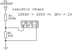
Should I use 1W resistors?
Thank you very much, you really helped me.
Now I can get working.
You will need a string of resistors. Lots of high ohm ones together to form the equivalent of one very high ohm resistor. Plus a single lower valued one which you would measure the voltage across. You can learn more by following this link on voltage dividers.
Please choose a name and stick to it for your posts on this site. I makes it much easier for me to answer your questions.
I want to measure voltage from induction coil. I need a voltage divider – 2 resistors in series. Which are their resistance, power ratings and does one part must be grounded? Do I need only 2 or more resistors? Thx.
1) Find the 2n3055 datasheet for this info.
2) No, Not directly.
3) This circuit
Happy New Year
Hi! 1)How much voltage and current I need to normally switch 2n3055?
2) Can I connect 10W audio amplifier output to emitter and base of 2n3055 to make my TC play music?
3) Can you post how to use mosfet
instead 2n3055 (circuit)?
Many thanks and Happy New Year!
I no longer have the coil pictured here so I will have to give you approximate values.
Space between turns: <10mm. Maybe 8mm
Angle from ground plane: <45°. Maybe 35-40°
The angle is actually not very important. It has only a minor effect on coupling vs. just a flat coil.
Ok Thanks for help just one more question what is angle of primary coil and what is distance between turns ?
Cry_wolf,
Both. Use an EMI filter between the mains supply and the NST to protect your mains ring from radio frequency interference. You can also place RF chokes on the output of the NST if you want to stop RF getting to the NST. Use a saftey gap to prevent overvoltage where needed.
Markku,
40mm diameter
How thick is that plastic drainage pipe
from that diy tesla coil.
Oh and im sorry if my english aren`t wery good because i speak Finland.
I’m using a 7.5kv /30ma franceformer and i wanted to know what would be better-> a safety spark gap or frequency chokes.(i do not want to ruin this BRAND NEW N.S.T. just like my ignition coil circuit)
It is based on the Plasma gun
ok. One more question: do you think you could send me a schematic diagram of the circuit you described in post No. 2323?
I couldn’t say for sure because I don’t know the specs of your flybacks diodes. I’m afraid you will have to guess if you can’t find any data on your diodes. It is also possible that there is a current limiting resistor built into it already. Maybe you can find some info on CRT transformers on the net.
ok. I understand what you mean. But what value resistor should I use at the output?
der strom,
The output of a flyback is not necessarily DC. The flyback you described has a built in diode rectifier as DC is needed for a CRT screen.
You would need to protect the internal diodes from over current and voltage spikes. The diodes are probably not rated for much current so you would need a resistor on the output. This should then be used to charge a large capacitor. Then from this capacitor you would charge your TC capacitor via an inductor. The inductor allows DC to flow through easily but prevents the high frequency of the TC getting back to your flyback. This method is used in the DIY Plasma Gun.
You could try connecting like you suggest, but this might destroy the diodes in your flyback.
Daniel Kuriloff,
Anti-parallel is where there are two outputs of opposite phase and therefore opposite polarity ant any one time. If you wanted to use four coils you would need to use two pairs of coils in anti-parallel. A pair being two coils in parallel. This would give you about 2x the voltage and 2x the current relative to a single coil.
For a Jacobs ladder it will work better with more current because this is what increases the plasma temperature and allows it to draw out further. The voltage of your power supply will just determine the size of the gap where the arc restarts.
I want to maximize voltage output from four ignition coils for a Jacobs ladder using a 555 timer circuit feeding a high power MOSFET. How can four coils be connected in an antiparallel fashon to get this? Is this possible?
because the output of a flyback transformer is already DC, could I just hitch it up with a HV capacitor and a spark gap and use it with a small tesla coil?
Yes it is possible, but the destructive power of it would not be like it is on the game. Anything with a metal shell would just divert all the electricity to the ground leaving anything inside totally safe. So basically most vehicles would be immune to attack and people could just wear something like chain mail over their entire body.
CAN YOU BUILD A TESLA TANK JUST LIKE REDALERT?
We have a similar disclaimer in the terms, but insurance is still needed too.
We were in the Tesla coil ring but we got kicked after we updated the site and forgot to tell them! Oops 🙂
“Sars,
We don’t generally make Tesla coils for sale because the insurance costs for such devices make it very expensive for small order quantities. “
all you need is a disclaimer like this site that sells tesla’s
http://www.amazing1.com/
http://www.amazing1.com/tesla.htm
Also, you guys at rm cybernetics should join the Tesla Coil ring web “club”, it will reference people to your site the link to join http://www.webring.org/cgi-bin/webring?home;ring=TeslaRing
(it gives you a cool little applet for the bottom of your page!)
I guess your diagram didn’t attach. Make sure it is a .jpg and less than 200kb. I can probably guess at the answers without the diagram.
1. You say it works well so I would say If it aint broke, don’t fix it.
2. It just depends if you want more voltage or more current. In parallel you get more current so the tank capacitor will charge faster therefore giving a higher spark rate (bps). In antiparallel you get more voltage. The energy stored in a capacitor is proportional to CV2 so you will get significantly more power in each firing of the spark gap but it will fire less often.
I chose parallel because my MMC was only rated for 20kV and I wanted the bps to be high so the TC output was smoother arcs as opposed to jagged sparks.
“A MOSFET would work as long as its rated for enough current. You will also need to use a higher gate (base for NPN) voltage and make sure there is a resistor from gate to ground “
1. In the attached circuit which works very well with two ignition coils connected in antiparallel fashon, should I put a resistor from the gate of the Mosfet to ground?
2. Which works better for joining ignition coils, parallel or antiparallel configuration. In your circuit they appear to be parallel and in the attached circuit they are antiparallel.
Thanks for the help
Daniel Kuriloff,
Yes you can use these types. Our surplus coils are resin filled and have the inputs at the opposite end of the coil.
The advantage of oil filled types is that the dielectric essentially self healing in the event of a brief internal arc. Internal arcing in a solid coil will probably result in permanent damage.
Sars,
We don’t generally make Tesla coils for sale because the insurance costs for such devices make it very expensive for small order quantities.
Could I just buy a Tesla coil from you dudes? How expensive would it be?
Is it possible to use a more modern, potted type of ignition coil instead of the canister oil filled type in a antiparalleled configuration for use in a Jacobs Ladder?
The noncanister types have the terminals further away from the HV out terminal reducung arcing when running the coils at High Voltages.
No, you would need to wind the coils and create a spark gap and topload yourself. We can only provide the parts in our shop.
Could you guys provide me with all the parts for the Tesla coil?
Yes.
Could you use a set of breaker points on a distributer to run the ignition coils instead of the electronics???
*****,
You could use leyden jars, but you must construct them well if they are to withstand 10kW.
Could you show me the DIY oscilloscope you said at the cathode ray tube in the shop
PLEASE!!!
Could I use a large bank of lyden jars for my 10,000 watt tesla coil?
We have some High Voltage Capacitors
Where would I find the capacitors?
This question has been asked on the ignition coil driver page and the answer was basically ‘it’s not adequate’. Check that page for further details.
hey! would the driver here work?
http://www.geocities.com/capecanaveral/lab/5322/coildrv.htm
i think its the same as yours
only the BFY51 is changed
I just reposted this (being sure that you will answer this) by the way i love your website thinking of building a wbsite like this XD
I WORSHIP YOU
MY HIGHNESS
XD
what if i use the 230 KV power supply to power a tesla coil with 1 meter spark gap and a MMC that is made of 36000 volt capacitors
WOULD THIS PRODUCE MORE THAN 2 MILLION VOLTS about 1 billion volts and above??
enought for powering the flouruscent bulb of a whole town then i will go to the guinest world record
WARNING::: I AM JUST 11 YeARS OLD!!!!!!!
XD
i have just baought a 555 timer that is a LM555 and a toshiba 2n3055 4D
and i got an ignition coil from a junkyard yesterday, but i dont have the resistors because OHMS is closed an i cant find any place to buy some
could you send me the full diagram of the ignition coil driver with the 555 timer and 2n3055 that doesnt use resistors
this is my diagram
:http://www.geocities.com/CapeCanaveral/Lab/5322/coildrv.htm
No. It is a totally different device.
Could the X-ray power supply that has a 230KV output bused as a tesla coil
so the toroid is the only thing i need
The driver could work, but you would need different coils
im jan keith from philipines
can that be used with a tesla magnifier???
A Spark gap TC will not be suitable for modula tion by music because its firing frequency is far lower than the average audio frewuency. You could probably make sounds, but music would not sound good.
The rate at which it fires must be greater than or equal to the nyquist frequency of your audio for it to be reproduced with any accuracy.
The simplest way to modulate an arc would be to just use an arc from an ignition coil.
ok so…
I have a bit of a noob question:
music with one of these, will it work if I can get the hookup right? (I plan on working with a fiber-optic system for the musical piece so it doesn’t fry/it doesn’t fry me. of course, if anyone has a better and easier suggestion for that, I’m all ears :D)
There are many different configurations for a Tesla Coil, they all do pretty much the same thing really. This just worked well for this DC charging method.
I wanted to ask why some schematics and circuit diagrams for teslas have the placing of the spark gap and the capacitor switched in comparison to your diagram. whats the difference? And here is some pics of my tesla. (yes the case is a pc power supply and the toroid is a door knob)
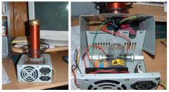
I wonder what effect a 3 phase tesla coil would produce?
not confusing with “3 phase powered” types, where 3 phase is used to power a single coil.
Im talking about setting up a master 3 phase oscilator, then a power switching stage, (igbt or mosfet) and create 3 identical secondaires and primary coils and feed them with 3 phase power….
I can emagine the arcs would rotate and probaly form some kind of vortex.. the voltage feild would probaly be quite interesting too.
maybe the basis for some type of lightning sheild maybe lol
i can emagine the only complication could be creating 3 identical secondaries at the same resonant frequency.
Im guessing that a microwave capacitor wont have enough volts, only 2500 volts (haha, its funny how i consider that a small amount of volts since i began this project)
justin,
The sine gen would need to an AC source of power and not just a signal source. Multiplier circuits are also not very efficient, so stepping up from 3.5V will waste a lot of energy. Your MOV would need to be big and very fast acting. They are not really meant for use like that so I think it would stop working after a while. Its a good idea and shows you are understanding the principles but I think the practical application of it would be difficult.
der strom,
The last paragraph on that diagram says “This SSTC diagram is over simplified. The design in the SSTC-1 uses an H-bridge and an antenna feedback system.”
The diagram is just used to explain the difference between an SSTC and an SGTC. It is not a functional circuit. It does also represent quite well the ignition coil driver, but without the signal generator.
Simon Dodd,
Yes, the transistors that would replace the spark gap would be activated by your audio signal. Changing an SGTC into an SSTC is not as simple as it might sound. The transistors in an SSCT typically only switch hundreds of volts. Switching kilovolts with a solid state device will be expensive and difficult. If you build an SSTC you will need a totally different circuit.
Thanks for that, I think I understand it all. I could “bodge” my circuit into a ss version by adding the transistor in place of the spark gap, but where would the switching control come from? would this be the point where I add the audio signal? I looked at your ignition coil driver circuit and understood that section but as you know my spark gap is after the ignition coil and I would still need to replace that to clean up the sound of the coil. I will keep building this coil as standard at first as it is my first coil but any help on this topic would be greatly appreciated as I have lots of ideas for using singing coils for some sort of HV orchestra (crazy I know but it could be fun!!) Would the transistor replacing the spark gap be controlled by the 555 circuit or the audio signal or something completely different hence the higher expense and complications?
Thanks again for all your help you guys run one of the best websites I have found just because of the comments section on everything and you quick and informed responses. thanks
Simon
I just found a solid state tesla coil on http://www.teslacoil.net/images/SSTC/. The schematic is at the bottom of the list and is labeled “untitled.JPG” Can you tell me if this would work correctly, or would it need more power?
dear rmc i had a great idea for my sstc but i need to know if it will work or not , i have a sine gen at 3.5v out and i was thinking of putting a big multiplier circuit on it to increase voltage then having a 3000v cap in parrallel with the multiplier and as a trigger a mov in series with the primary/multiplier , the way i figure it, i should have 275v running through my primary coil but im not sure if this set up will work can you offer me some advice.
Simon Dodd,
Making the arc from the your ignition coil sing would not be to difficult. See the comments on the ignition coil driver page.
Theoretically you just need to replace the spark gap with a solid state device and have another signal (or feedback) to switch this on and off. Unfortunatley the practical application of high voltage, high current, high frequency switching is not so simple. For a true SSTC you will need a lot more cash to spend and a totally different design. Google SSTC for some shematics and examples.
der strom,
Nope, there is definatley a spark gap shown on figure 1 and figure 2.
simon and rmcybernetics,
The second figure on that site IS a sstc–and run using a 555 timer and no spark gap (as far as I can see). I think you may have seen Fig. 1 istead of Fig. 2.
If i’m wrong, I apoligize for the inconvenience.
Thanks for that, what would be the best sort of coil for making it sing, would it be a solid state coil and what is the best way of creating one of these (preferably using what I have already created) Would the circuitry be pretty much the same on the low voltage side but the main changes would be on the high voltage section mainly the spark gap would be replaced with solid state components or is it a bit more complex than that.
thanks again in advance
Simon
That is not a solid state Tesla coil. An SSTC has no spark gap at all because this is replaced by solid state components such as IGBTs or MOSFETs.
A singing arc is usualy produced by amplitude modulation (AM) of the output. This will be tricky with a spark gap coil because the firing rate is not well defined. You could AM the signal from the 555 so that the ignition coil output varies with the input sound. This would alter the firing rate of the spark gap when the sound alters, but I doubt it would be sufficient to make any sort of quality sound, if even recognisable at all.
Proper HV caps or an MMC are best, but as you can see from Santas TC, the foil and bottle method works well.
OK guys, thanks again for the great site and the time you put into it. I am currently in the final stages of building my first coil and have gone for the solid state coil on this page
http://www.uoguelph.ca/~antoon/circ/hv/ss-tesla/ss-tesla.html
I have nearly finished it but am thinking ahead to getting it to “sing” via some sort of MIDI control. Would this involve a MIDI to CV converter to change the frequency of the pulse generator coming from the 555 chip or is it not that simple?
Also what is the best style of HV capacitor to start with (as you can see i need a 1500pF rated at 10KV) I was thinking of a simple glass plate with Aluminium foil but some of the beer/wine bottle versions you have look slightly easier.
Thanks in advance
Simon
It depends on your coil, frequency, supply voltage and what load you have on it. Typical coil on 12V with load will draw 5A. One 2n3055 will switch 15A so if you keep it cool, one will be fine.
So if I used only one to drive a single ignition coil, it might not handle the power very well?
der strom,
More 2n3055s are used when driving more coils together to handle the power.
Awsome High Voltage,
Are you using a HV diode between HV output and capacitor?
I used a 20kv 35ma obit but my spark gap wont fire. if i take the cap of it works. can you help me?
What would be the benefits of having more 2N3055s in your ignition coil driver?
In your circuit for the dual ignition coil driver, can transistor BFY61 be just about any other NPN transistor?
der strom,
The 358 should work ok. Check the pinout on the datasheets so you can make sure you use the correct pins.
Devn,
The ringing effects is caused by a combination of capacitance and inductance. Even a small amount of stray/parasitic inductance will cause this. When the cap discharges, the flow of current stores some of the capacitors energy in a magnetic field. As the cap discharges, the magnetic field collapses and induces a current back into the circuit in the opposite direction. This process can repeat many times over during just a single spark which is what gives you the AC type waveform you see.
A diode placed in series with your spark gap would stop most of the ringing, but finding a diode that can withstand the large current pulse and high reverse voltage could be expensive.
Another option is to try to extinguish the spark before the voltage has time to reverse. This may be difficult in practice as the timing would need to be quite precise. Improved quenching can be achieved through the use of a rotary spark gap, air pressure, permanent magnets, or some other mechanical means. A large magnet placed either side of the spark at 90 degrees to the flow of current will cause the arc to immediately deflect when it forms. If the deflection is enough, it will stretch the arc to the point where it is extinguished.
To get a truly unidirectional pulse will be very difficult indeed because all the components will have some stray inductance and capacitance. Improved spark gap quenching will certainly help though.
I really appreciate the time and effort you put into this site. Thank you!
I built the PWM and am using it with 3 ign coils. It charges a .19uF HV cap. This cap is discharges to ground via a spark gap.
If we look at the ‘scope and analyse the actual arc discharge it oscillates. How can I prevent this “ringing” ie. I want to control the length of the arc dicharge sothat each discharge is unidirectional. Tesla stresses this in much of his writing on radiant energy.
Any ideas to help? Thanks
Devn
Does it have to be a 393? Because I have a 358, but I’m not sure if it would work right. Would they work the same?
Yes. You can use as many or as few as you need. They are all connected in parallel so you don’t need to change the circuit.
I was just looking at your Ignition coil driver and I was wondering if it would be a way to use only two 2N3055 instead of four of them?
I understand. A 12V wall adapter is probably not going to work too well unless it can handle over 5A @ 12V (>60W).
I don’t mind the questions, I just want you to learn the science involved and not just try to copy diagrams.
Because I have limited access to electronics parts, I try to find schematics that use parts that I have. I might be able to find the parts that I need to build the circuit that is shown here.
For this circuit, would it be possible to use a 12v wall adapter to run this coil instead of a 12-24 volt battery, as long as I don’t use it to run a Tesla Coil?
I’m sorry for all of the questions, but I am still trying to learn more about high voltage electronics.
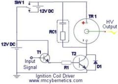
It has limited variability and no EMF protection. If you build it as shown on that site, it is absolutely guaranteed to self destruct at some point while you are making sparks. Why use some random circuit when there are plenty of examples here with many questions asked and answered already? You seem to want to make things difficult for yourself. The circuits here are tried and tested and many of the difficulties people have had are discussed on the same pages as the diagrams. There are also many suggestions on how to improve them or protect them from EMF generated by ignition coils. Look at this circuit or this. Read all the text including comments and questions. Read all the pages in the learn electronics section. Make sure you understand it all. Google around to get even more related information. I’m afraid you can’t just join the dots when it comes to power electronics like this, you must understand what you are doing or you will keep having problems. If you insist on trying to take shortcuts and ignoring the advice given, then I don’t see how I can help you further.
What’s wrong with it? Do you have any ideas of how to make it more reliable?
No. It’s not very reliable.
Ok. thanks. I’ll get started right away on the new circuit. Do you think this circuit would work for a good driver? I got it from http://www.geocities.com/capecanaveral/lab/5322/coildrv.gif
You need a proper square wave driver to get the most out of your coil.
Thanks. Do you know if there is anything i can replace the dimmer switch with (keeping the rest of the circuit the same) to get better arcs? or do i need to totally rebuild my driver using a 555 timer?
It isn’t quite an arc, and it definately doesn’t rise– even a little bit. it is just a very frequent (~60 sparks/second) blue SPARK. I don’t know what’s wrong–maybe something’s wrong with the driver, because I bought a brand new coil, and it did the exact same thing as it did with my old coil. Do you have any idea how I might be able to improve it?
Spark or arc? Spark typically refers to a thin white jagged line which lasts for a fraction of a seccond. They usually make a crackling sound. An arc would be a continuous plasma fillament which manages to stay hot between the curent pulses. They are usualy purple and tend to arch upwards due to the heat.
In parallel sparks will look the same, but you will be able to draw out arcs further than you would with a single coil. The will still only jump the same distance.
In anti-parallel the sparks will jump further due to increased voltage. Arcs should also be larger than a single coil.
I tried putting two ignition coils in paralell like you did in your circuit, but I only got the size spark that I got from one coil, but when I hitched them up in anti-paralell, I got 3 1/2 cm. sparks. Do you know what was wrong with the other configuration?
Here’s the circuit I had tried (just the coils):
I am planning to start simple– with the mini tesla coil that i showed you earlier on, and then I also built a 14 inch tesla coil. The 6 foot tall tesla coil is a future plan that I will probably wait to build until I am more experienced in high voltage electronics. I am just trying to get all the info now, so when I’m ready I can know exactly what i’m doing.
My advice is to start small and simple. Without some HV experience or even general electronics, the result of your project is likely to be the death/injury of you or a bystander. I can’t emphasise enough how dangerous a hobby Tesla coiling is for a beginner. Power electronics (especially at this voltage and frequency) is as much of an art as it is science. Allthough the operation of a TC is theoreticaly quite simple, there are many variables to be considered for a real system, and some which are not known precisley. Any mistakes in a large high power system will be expensive and potentially deadly. Mistakes made when making a small battery operated system are much less expensive and less likley to kill anyone.
Not normally. If we have some left after a project they will go in the surplus store. Low voltage bits would go in the electronics category and HV components in the High Voltage category.
Some more items have been added today.
Hey. I looked around your shop online yesterday. Do you sell electrical components seperately? I couldn’t find any. Which category are they under?
No SSTC yet. A standard square wave oscillator will be ok for a drive signal but you will still need something like IGBT’s for power switching.
MR rmc do you have any palns for a solid state tesla coil driver? if not will a standard square wave oscillator drive a tesla? ohh and one more thing does the tesla exert a lot of feedback current into the primary drive circuit, if so i need to make a gate or something.
sincerly machine of pure excellance.
Start simple. Use the 555/393 oscillator circuit to dim or flash an LED. If that doesn’t work there is no point adding aything else to the circuit.
I tried to use the PWM alone to drive my ignition coil CR-800 12 volts but it did not work and I just cant figure-out why? Can you still help me on this? Thanks again.
This circuit will drive an ignition coil alone but the MOSFET will heat up quickly so a good heat sink is needed. You should still use the snubber RC1 shown on the ignition coil driver page to help protect the circuit from HV spikes.
You can also connect the MOSFETs in parallel.
Common mains driven TCs use sine wave driven transformers with a low frequency (50 – 60 Hz). This allows the tank capacitor to charge in 1/4 of a cycle and therefore fire many times per second. The voltage change in these types of transformers is proportional to the difference in turns on the primary and secondary sides.
The voltage rise in an ignition coil is a proportional to dI/dt (the rate of change of current). The square wave driver gives a HV output made from high frequency pulses which are too quick to charge the tank capacitor fully on each cycle. The diode serves to keep the pulses unidirectional and to stop the capacitor discharging back into the ignition coil.
Can you please explain why the conventional tesla coil are not using high voltage rectifier but are capable of producing strong sparks.
In your shop I’ve seen the high voltage rectifier your selling will it work ok in my circuit or need a much highier current rating? Thanks again. Your doing great with your great website. More power to you.
der strom,
The magnetic field is pretty well conntained within the case but you certainly should see some deflection of the compass if it close enough.
Making sparks broadcasts a wide spectrum of RF noise which will intefere with many appliences. Most modern exipment has some sort of filter to tr to reduce interference problems.
crisH,
You can get a rough idea of the pinout by measuring the resistance between the pins and drawing a diagram as you go. The one in our surplus store was tested with our PWM-OC10A by just trying combinations of pins and measuring the corresponding output voltage. Two of the pins (I can’t remember which) had a low impedance and gave a steady 20kV output.
Yes a few of us should be visiting the Teslathon. I’ll bring the plasma gun too. See you there.
I have a flyback generator exactly like the one in your surplus shop but wondered if you could kindly supply any info on pin out identification….there are a dozen to choose from on the underside!
Also, any chance of you turning up at the Cambrige Teslathon with your mini tesla and latest tesla project…It’s at the Cambridge Museum of industrial technology on w/e of 27-28th of October…I’m sure your gas plasma tesla coil would generate alot of interest! hope you and your team can make it.
You can use our shop. You can pay with credit/debit card without having to sign up to paypal. After clicking “checkout” there is a small text link above the pictures of credit card logos which are near the bottom of the page. I don’t know where else to suggest. They are getting discontinued from lots of shops these days.
The higher voltage capacitors will probably have a much lower capacitance. If you charge them with only a small voltage the spark you get from shorting its terminals would be negligible.
You are charging your low voltage caps because the small gap you leave breaks the connection to your coil just in time for some of the charge to remain.
I would guess that this is your problem. Without a proper HV diode, you will not be able to charge caps correctly.
I would now assume that the diode you do have is damaged and will probably allow current to flow in both directions.
You might be able to get away with connecting lots of lower voltage diodes in series, but this method can cause diode failiure.
der strom,
Look up information about a ‘Faraday Cage’ works for info on shielding EM interference.
Claydough,
There is not much info because they are simply a single piece of metal (or several joined to make one).
Imagine the metal as a reservoir for ‘electrical water’. You connect this to one end of a hose (your secondary coil) to allow it to be filled and emptied while the current flows back and forth in the coil. The opposite end of the coil is connected to the ground (literally) which supply’s all the ‘water’. The ‘water’ is pumped up and down the secondary coil with the magnetic fields produced by the primary circuit.
Hello all, first off i want to say, i love your site, and second, I’m a beginner coiler, and i’ve noticed that there isn’t alot of information about the toroids. How are they attached to the secondary coils exactly? Is there just one wire from the coil connecting the two parts? THANKS SO MUCH!
Yes if its also rated for 15kV or more.
Ok. thanks. Earlier you said that i would need nF capacitors for my mini tesla coil. i looked them up on the internet, and the film capacitor i found was rated for 1 nF and had the number 102 on it. is this what i need?
We have some HV diodes in the surplus items section. Our online payments are handled by PayPal, but you can pay using a card without a PayPal account if required. You can also pay by post, but make sure to email your order details before sending any payment.
I’m not sure about Radio Shack stores as we don’t have those in the UK. If it is the same as RS, then you may be able to find some there.
Ok. thanks a lot. Do you know where i can get a rectifier rated for a high voltage? do you think Radio Shack might carry them?
If the caps you have are of similar physical size, the HV ones are likely to have a much lower capacitance. Most capacitors rated in the kV range will be much smaller than F or uF unless they are physically quite large. This image show some typical HV ceramic capacitors and some HV diodes) The left most caps are rated for 1kV and 4.7nF.
Ok. thanx. I have a question about my ignition coil: How come it only charges 200v-400v capacitors, but not my 1kv-2kv caps? is there any way i can adjust this?
Also, I have never seen a cap rated for nF. I have only seen them in uF and F. could u send a pic or something?
Thanks very much for all of your answers!!!
The value of the cap will need to be adjusted so that the resonant frequency of the primary circuit can be made to match that of the secondary.
It’s probably best to make some sort of MMC or have a selection of different sized caps to try. With an MMC you can add/remove a cap to increase/decrease the frequency as needed. The cap used in the plasma gun was just 2nF made from two 1nF ceramic disc caps in parallel. The optimum value was found by using an MMC of much smaller valued caps and adjusting it as described above.
A single HV diode in series with the output of the ignition coil will be enough to allow you to charge the tank capacitor.
120V @ 50Hz would cause too much current to flow in the ignition coil. This would cause it to burn out.
Mains powered Tesla coils often use a neon sign transformer as it can be powered from mains voltage.
gr8! thanks a lot. the only problem is that i only have 1 ignition coil. is there a way to make it work with only 1 of them?
by the way, i built a simple driver circuit for the ignition coil. it plugs into 120v AC from the wall, and it has a dimmer switch so the coil does’n get fried. is it possible, or safe, to use power that is directly plugged into the wall for my mini tesla coil? or will the “backflow” ruin the power supply?
Again, thanx a lot!
Chris Henderson,
If you are replacing a transistor in the same position in your array than there must be something wrong with either the wiring of the circuit or the other transistors.
If it’s heating up and eventually blowing, this is due to it switching power beyond its ratings. This would lead me to believe that the other transistors are either faulty not switching on for some reason.
You can test a 2n3055 by replacing your ignition coil with a load that will give you an idea of current flow such as a motor or light bulb. The faster/brighter it is the more current is flowing.
Remove the signal source from the base pins of the transistors and make sure all transistors are separated from each other. Now connect the signal or a DC voltage to the base pin of the 2n3055 under test and take note of the power level shown my your load. Test each 2n3055 like this to see if there are any major differences. Compare results to a new transistor so you can tell if they are performing correctly.
der Strom,
The rectified output of a single ignition coil driven by a 12V pulse modulation circuit is likley to be enough power for charging the tank capacitor of such a small TC. You should refer to the DIY Plasma gun page for details of building a tiny Tesla coil.
Ok. Thanx a lot!!!
Another question: What ignition coil/tesla coil circuit should i use for a tesla coil only 4 inches high?
here is a picture of it.
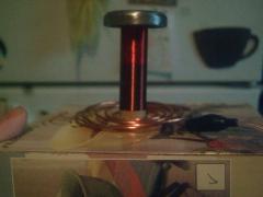
I have costructed a 4x 2n3055 driver hooked up to a pair of ignition coils, works ok but output only 1 and a 1/2″ sparks from tesla. However as I try to increase power i.e. widening spark gap,or increasing supply voltage to driver, the 2nd 2n3055 in the chain of 4 gets extremely hot and often blows. The other 3 power transistors don’t get particularly hot at all…So, do you have any ideas for solving this problem as I have’nt many transistors left to replace the blown ones with!
You should be supervised by an adult familiar with the safety precautions for high voltage devices. This person would be able to purchase an NST and help install it safely.
(changed from nino de alto voltaje)
I would love to be able to buy stuff on ebay, but i’m “underage”. i’m not 18.
a couple of days ago i tried ebay, but they wouldn’t allow me to register because i am under 18.
An ignition coil will only be enough for very small tesla coils. You can usually get a neon sign transformer (NST) from eBay.
Hey! I want to make a 6 ft tall tesla coil for a science project. i’ve drawn out all the plans and everything, but i still can’t figure out what kind of xfmr to use for something that size. all ive got is an old 12 v Bosch ignition coil that i got for free, and i dont think that would work very well for a giant TC.
I’ve read that neon sign xfmrs are often used for tesla coils that size, but i just can’t get my hands on ANY!!! any other suggestions?
Thanx a lot!!!
–nino-de-voltaje
john keth junior:
I’ve never used a magneto, so I couldn’t say.
will:
Check the lower end of the coil is connected to a good ground (like a metal rod in the earth.
Check the coupling is not so close that plasma is forming between the primary and secondary coils at the closest point.
If they are ok then I would guess that it is not in tune. The primary circuit must be adjusted so that its resonant frequency exactly matches that of the secondary coil with topload. The most common way to do this is to adjust the number of primary turns by tapping off at different points. More turns = lower frequency
Bigger capacitor = lower frequency
Bigger Topload = lower frequency
hi, ive made a tesla coil and everything is working perfectly apart from the secondry coil, i am getting no sparks from the top and i dont have a clue whats wrong, can u help??
hey rmc i was pondering around your site and from what i gather people seem to have trouble finding a good transformer. would a magneto be good you know those thigs from the little petrol lawn mower engines? i thought they had high current as well as voltage if not please notify me right away
Sounds about right.
I wish i knew how to make a solid state tesla coil, my coil uses a 15,000v 30 millamp neon transformer i need Rf chokes to protect the transformer how can i make my own Rf chokes? Im going to use a 1 inch 25mm diameter pvc pipe wound with a few hundred turns of 20 or 22 awg insulated wire will this work? are my dimensions correct?
2n3055 transistors are used because they have a high current switching capability, are available pretty much anywere that sells transistors, and are resonably priced. They are not the best choice, but they are popular for this sort of circuit.
A MOSFET would work as long as its rated for enough current. You will also need to use a higher gate (base for NPN) voltage and make sure there is a resistor from gate to ground. This is important for switching the transistor off as quickly as possible.
why do you use 2n3055 power transistors, is it just because they are easily available and would mosfets connected in parrallel work or is there some problem with using them.
I have seen a circuit where someone just wrapped a few turns of wire around the metal can of the ignition coil for use as the feedback signal. It’s probably worth trying that first.
thanks i have replaced my cap with a high voltage ceramic cap 0.1 uf = 100nf witch should work better than the dialectric cap i have currently. i was also thinking of taling apart my auto coil as it is crappy and rapping the wires around a ferret core so i can put in the self resinator circuit would this be a good idea?
That sort of driver circuit offers the advantage of automatically running at the resonant frequency of the transformer, but this also means you can’t adjust the frequency to match your spark gap for example. Also those big resistors dissipate energy as heat, reducing the overall efficiency.
Generally the frequency of a TC output is too high and the current is too low for use as a power supply like this.
Some people consider the car ignition coil and flyback transformers as Tesla coils with solid ferromagnetic cores. Either of these will work like shown on this page.
Another version is the Tesla magnifier which is a standard (air cored) TC with an extra coil simply connected to the output.
20 secs is a long time between fring.
What gap do you have? About 5mm should do it. If your cpacitor is only small (< 10nF) then it should charge quickly, so if it's not, your HV supply may not be delivering enough current.
Our Power Pulse Modulator makes a great flyback driver. It is similar to this circuit, but with added features such as inductive spike protection, back EMF and power monitoring, and built in cooling.
i got my tesla kinda working but the spark gap on switches every 20 seconds or so . do i need a higher voltage input ? the voltage isnt all that high. im using a flyback at about 10,000 to 20,000 volts or about 1cm long. could you suggest a flyback driver circuit?
wouldnt the current from a SLA battery fry the ne555 chip? or would the chip only withdraw the current that it requires from the battery? great website by the way.
…. and here it is. The DIY Mini Tesla Coil / Plasma Gun!
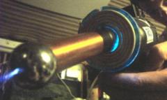
every thing rocks here but a complete diagram is completely missing
how have u created the capacitor bank provided logical diagram n reality has lot differences
how to connect the coil
seems like i m going to need a complete diagram
n the cheaper, smaller n safer version of the TC will have same beautiful arcs
The current at the output of this TC is below what would be considered lethal, but it would still give a painful prickling sensation if you were to be struck by an arc.
There is still a lethal level of current flowing in the primary circuit though. Touching this would likely result in serious injury or death.
A mains adapter is not likely to be able to provide enough power (unless it’s a real expensive one) and it may be susceptible to damage from RF as well as allowing RF to get on your mains line and damage your household electrical items.
Hi i just got net n found tesla coil.
I want to know that the simple coil prepared is hazardous for a person? what if someone got in contact to discharge from the coil? n can some one use a 12/ 24 adapter instead of a battery?
Dragunov-21:
MOT’s are dangerous because they have a low impedance which allows them to put out a large amount of power. The impedance is what limits the current drawn from the power supply (the mains in most cases)
If you run your MOT from your power pack, the current will already be limited to 3A because of the impedance (or overload protection) of the power pack its self. The low input voltage (4V) will also prevent any large currents from flowing. The MOT is designed for a mains input of 240V (UK) and gives an output of a few kV. This is only a small step up ratio of about 10x the input voltage. So if you use an input of 4V you are only likely to get about 40V out.
Personally I would just completely avoid using an MOT and stick to high ratio coils like ignition coils. They are safer, but you should still be very careful as no DIY high voltage device should ever be considered safe. Also if you are charging capacitors, the danger is hugely magnified because they can store a lethal energy jolt that can be delivered in an instant.
Dan:
The current you get depends on a lot of things like input power, frequency and pulse width. It also varies between the different coil types or models.
You can measure the current using a standard voltmeter and a low resistance (1 ohm or less) power resistor.
If you place the resistor between the output and ground it will be almost shorting your coil and therefore drawing lots of current. If you measure the voltage across the resistor you can then use ohms law to calculate the current flowing through it. (I = V / R)
What the average output current of an ignition coil? Is is based upon the current going into the coil?
I’m building a tesla and so far have managed to get a auto-coil. I’ve been running it off a 12VDC Lab Powerpack at 4VDC, using a relay as a rapid switching circuit, (haven’t actually built primary or secondary coils yet, just been messing around with a spark gap). There’s a repair shop that’s willing to give me a half dozen MOTs, but after reading Ian’s story I’m thinking I’d be better off wearing the cost of buying a bunch more autocoils. If I’m running a bunch of MOTs from a DC Powerpack, am I putting myself in danger? (Output at 4V is around 3A).
mad scientist:
The current depends on the size of the transformer. It could be anything. A higher firing rate for a spark gap Tesla coil will give longer output arcs.
Thanks for sharing your story DyD.
For those who don’t know, an MW transformer is the transformer from a microwave oven. These things will deliver lethal electric current in an instant. Don’t mess with them.
After seeing Ian’s site, I now understand why my grandpa has said “Never, ever, EVER, use a MW transformer…”
Although the can picture is pretty sweet…
Peter et alia!

I am a high schooler who has had a long time fascination with electronics, esp. high voltage.In one of my attempts to amuse myself with metal etching, I constructed an arc welder USING A MW TRANSFORMER! Please, Please don’t risk injuring yourself. My blog is caringbridge.com/visit/iandaniher
I wound up in Shriner’s Burn Hospital for THREE MONTHS! Please email me at explodingmind@gmail.com with any questions.
Not at the time as it was made with pretty much what was allready available.
There is a version of this driver circuit which uses a MOSFET. It is avalable as a power pulse modulator or the DIY pulse controller
Did you consider using N-channel power MOSFETs in the ignition coil driver circuit rather than BJTs?
Cool. Post a picture if you can.
It’s difficult to say if this would improve your power output. Making the coil shorter and wider may improve the coupling but it could increase the losses in the system due to corona discharge or capacitive coupling to ground.
If you have the time and materials it may be worth trying a few different versions of your secondary coil to help you learn how changing different parameters will effect the system.
Ok. My sgtc works well. Again many many thanks for the useful information. Also question: if i extend diameter of my secondary coil (with remaining turns and wire diameter) as well as changes inductance,capacitance,etc output power will also increase?
An NST running from mains will provide more power but it means that there is a greatly increased danger of fatal electric shock.
Small ones can often be found on ebay for about £30 + shipping.
I would like to ask whether neon sign transformer can work better than these electric supply (like power pulse generator)? How much(estimate) the cost of one small neon sign transformer?Iwant to set up my budget for buying these appliences.
artemon:
Was it your diode string or did you find some other problem that you fixed to get it working?
The most common primary coil is a flat spiral for spark gap Tesla coils because it concentrates the magnetic flux at the base of the secondary coil and allows for loose coupling to prevent flashover. Some people use a conical one to increasec coupling slightly but it makes only a little difference in practice.
For very small tesla coils such as single or dual ignition coil driven types it is sometimes possible to use much tighter coupling. Wrapping the base of the secondary with several layers of insulation and then wrapping a primary coil onto that can provide a large amount of coupling for situations where the output power is not too great.
mad scientist:
Transformers, motors, or the ballasts from inside flourescent light fittings are typical sources of enamled wire.
Your transformer should be earthed, but Tesla coils are just not safe and should never be touched when active.
A very rough estimate for output voltage is for each mm of spark there is 1kV. This applies for a spark between two smooth round electrodes. The spark will jump further between wire tips because of the higher concentration of electic field.
S#*t! when i change 2N3055 to an MOSFET(for my flyback transformer), the arc produced over1 inch, and i shocked myself. The spark was amazing and how do i estimate the voltage produced?
For safety reasons, i want to earth my power supply. where should i joint the earth wire?(the primary coil, or the flyback transformer?)
Hm. there is difference between Primary coil will be flat spiral,helical or inverted conical spiral coil? and what are the best-type for small,medium and big coils? thanks. and also,where to find all-in-one tesla coil calculator? Because in mine there’s no one for inverted conical spiral coil(
Finally, my flyback transformer works, giving 1.2cm arc. Now, I am out of enameled copper wire, Ihave many AWG 40 wires as much as 50metres long but awg 33 is just only a little.Could you suggest some sources of enameled wire?(except transformer)
New or old 2n3055 makes no difference.
The number you use just depends on how much current you want to switch. Each 2n3055 will handle a maximum of 15A.
The wire you need depends on eveything else you use (size of topload, primary inductance, primary capacitance). You must calculate this yourself.
Flyback transformers are usually designed to work at high frequencies.
Instead of four 2N3055, can I use just only one brand new 2N3055(for a flyback transformer)? What is the length of enameled wire needed of the secondary coil?(AWG 37, Diameter of coil=2 inch) Can a flyback transformer operated at high frequencies about 68khz?
Not sure I understand what you are doing in the fist part of your message (can u draw a diagram?) but I have to say; Don’t hold any wires when making sparks! Especially if there is a capacitor in the circuit. One jolt could stop your heart or make you jump and injure yourself.
The capacitance of a capacitor is a measure of how much energy it can store for a given voltage. 18nF is 2.25x the 8nF capcitor so it will hold 2.25x the energy when charge to the same voltage. Imagine it as a container with a size measured in farads. A bigger container will hold more but it will take longer to fill and longer to empty.
Heh.damn i’m a flooder) Ok. i’ve managed with my MMC . ok. my tesla partially work,giving a 5 mm sparks)))) it is less,than from ignition coil)))ok. problem no1: first time it occured in my jacobs ladder. So:between wire(im holding it in a hand) and fixed electrode occurs sparks,arcs..so ok. But if i’ll attach this wire to another electrode of my Vee shape,it wont fire! Why? also in my tesla coil: if i attach all HV wires to their places(input of TC),spark gap will not shoot. But if i take (-) wire and slightly move it to my input of tesla coil,spark will occur between wire and input, and also spark gap will work normally. What is this?
Question: what’s the difference between ~8nF mmc or ~18nF? (i know that changes resonant frequency,but what else changes? performace changes?longer time to recharge?) thanks. and sorry for that amount of questions(
There are a few reasons that an MMC could fail.
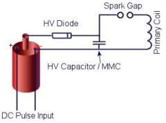
1. Over voltage. It’s quite possible that you are getting more than 21 kV from you coil. If your spark gap is smaller then the cap will discharge before it reaches a higher voltage. As I mentioned before, the cap should be rated for about 2x the voltage you intend to charge it to.
2. Over current. The capacitors you used may not be able to handle the large current pulse caused when rapidly discharged.
3. Internal mechanical failiure. When a cap is charged, the internal plates are strongly attacted to eachother. When they are suddenly discharged the force is released which causes a shockwave in the caps. This can cause some caps to fail but it is usually after many cycles.
Could you please draw a wire connections diagram,starting from HV output of ignition coil. maybe im doing something wrong…. thanks.
eem. whats wrong? i’ve burned my second MMC ((( why it happening? it is 21kv 18.85 nF. It is charged by ignition coil powered by 20V 3A. it burns in 1 shot. it charges,then fire…and no fire more((( WHYY???
Can I use 0.8 inch diameter PVC pipe for my secondary coil?
Yes there will be a large voltage drop across the chain and yes some current will flow back through the resistors. It’s not useless though because the total resistance of the chain is very large which allows only a small reverse current to flow.
The only alternative is to use proper high voltage diodes. There’s usually plenty on eBay.
But how chain of diodes will work? 1st problem:all diodes has inner opening resistance and chain of 15 diodes will give pretty enough.
2nd: 10M resistor across each diode will conduct pulse back,so diode will be useless…or i’m wrong?
A pulse generator will work to drive the flybacks.
You can’t connect them in series.
Now, I have two flyback transformer. Could you show me some circuits that can use with my flyback transformer? Also can I connect these transformers in series to get higher voltage?
A least 15.
A solid state tesla coil (SSTC) uses a solid state device such as a transistor instead of a spark gap. Unfortunatley it is not as simple as just replacing the spark gap as there are alls sorts of things needed to make it all work well. They are expensive and difficult to make. They are also easy to break if they are not made well enough.
How many i would need of them?) and could you explain what is soild state tesla coil? cause i cant find even basic information of it..only strange circuits))))
You may get away with it. I’d add about 10M resistor in parallel with each diode though. This helps equalize the voltage along the chain.
a chain of 1n4007 wont pass? 🙂
The total voltage rating for your MMC should be about 2x the voltage that you will charge it to. This is just a safety margin so that any voltage spikes wont destroy it. A typical metal can style ignition coil like shown on this page will give about 20-30kV peak when unloaded and driven with a good 12V driver circuit. The rectified DC voltage would probably be about 50% less.
800 or so turns is pretty typical for a TC secondary coil. 2-3k would be too many for a couple of reasons. The inductance and self capacitance will be very large and therefore give the coil a very low resonant frequency. Your MMC or primary coil would need to be very large to match the frequency. The other reason is that the long thin wire will have a large resistance therefore lowering the Q factor of the coil.
You will need to rectify the output of the ignition coils to charge the MMC. A single high voltage diode between the coil output and the MMC would do it. The anode of the diode (the end with a stripe) would be connected to the MMC. I would recommend placing a choke (an inductor) between the diode and MMC to help protect the diode from surges.
The base of the secondary coil should be connected to the ground for it to resonate properly. The ground connection used sould not be the same as the rest of the circuit. You need a dedicated RF ground such as a metal rod in the earth.
Primary coil:- 14 turns on 6 inch plastic tube.
Secondary Coil:- 950 turns on 2 inch cardboard tube.About 5 coats of Varnish.
Spark Gap:- Static, 2*10mm bolts.
Capacitor:- 1 wine bottle filled with salt solution and covered with foil ( value unkown ).
Power:- 2 ignition coils ( not matched pair ).
oops nearly forgot :-4k7 Capacitor across the load.
also some questions: why 20kv mmc? cause 2 ignition coil in parallel gives 20kv??O_o and i have only 0.15 mm copper wire,for secondary coil,and i’ve maked 1 small coil(it is about 13.5 cm tall and has about 830 turns) but if i will use this wire on larger tesla coil,and there will be about 2-3k of turns? it will only changes the resonant frequency,or turns surely need to be in 800-1000 range? thanks)
Nice1 Santa.
artemon: See post 832 and replies for some more MMC info
mad scientist: The flyback transformers in a CRT have a built in rectifier so that the output is already DC. This should be able to handle about the same sort of power as a single ignition coil.
to Santa: nice work! i like it) what is your mmc cap size? what’s the spark gap? static or rotary?
to RMCybernetics: also,question about MMC cap size) what is it? )
Very nice. What type of spark gap do u used? static or rotary? eem. input was 220vac or 12vdc? and what is your mmc cap size? about 0.025 uF?
can i use a flyback power supply obtained from a monitor of a computer? would it enough to create high voltages needed by the tesla coil?
what is the measurements for the secondary tube?
how to increase the output voltage for this tesla coil?
Ignition Coil powered Tesla.First Light..
Making and breaking arcs causes big voltage spikes that need to be snubbed before they reach the sensitive components.
Placing a snubber (such as a capacitor and resistor in series) in parralel with the coils input terminals will help. You will need to experiment with the values of capacitance you need. The snubber will absorb some of the energy so that the circuit is protected but there will be a small reduction in the output voltage.
thanks. Heh) now i started smoking lm393) heh) i’ve purchased voltage suppressor 1.5Ke15A and putted it between ground and signal output of lm393..and no use) lm393 burns when 1st arc creates. hm. any idea how to prevent this? because Santa (in homemade pulse controller post) had same problem,but i cant understand the solution(((
Almost any medium power bipolar npn transistor will do.
also i’d like to know what is BFY51 alternative? because i cant find bfy51 in nearest shops,but signal from generator(running at separate battery 9v) is too poor,to drive 2n3055. is there popular models similar to bfy51?
Trying to calculate (accuratley) the resonant frequency of a Tesla coil system can be difficult and time consuming. There are a few free programs and websites available that will help you. You can input things like your wire size and number of turns, the Tesla coil calculator will then give you an answer. You should take it as a pretty rough guide though. Tuning is almost always required after construction. As a formula you get the one shown on the left, but you may need further calculations/measurments to get the values to plug into this formula.
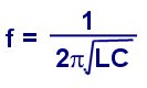
how to calculate the resonance frequency?
Just a few tips on TC building……
With my battery powered tesla coil, just a few turns out on the primary coil would make the difference between 1cm and 20cm sparks. Here are a few tips that may help you in the process.
Reducing Losses
Connecting wires in the primary circuit (between spark gap, capacitor, and primary coil) should be as short as possible and using thick wire. This helps reduce lost energy due to current heating in the wires.
All HV interconnecting wires should be well insulated and kept away from eachother. Avoid trailing wires accross surfaces such as a wooden base too. This helps reduce losses from capacitave coupling and eddy currents.
Using a transistor to switch the ignition coil, could also be adding resistance to the circuit. You could add more identical transistors in parralel so that more current can be pulsed through the coil.
Use a seperate ground connection for the base of your secondary coil. Using thick wire connect it to a good ground source such as a long copper pipe hammered into the ground
Tuning
It is important that all the parts in a tesla coil are resonating at the same frequency, otherwise power is not effectivley transfered.
The secondary coil is pretty much set in its resonant frequency, but small adjustments can be made by altering the size of the topload (torroid or sphere). Increasing the size of the topload will reduce the resonant frequency of the secondary coil (think about a bigger sphere means it takes more time to ‘fill’ with charge). It will also mean that sparks will not jump out on their own as easily, but they will be bigger when they do.
Tuning the primary curcuit is achived by altering the capacitance of the tank cap, or adjusting the number of turns in the primary circuit. The easiest way is usualy to adjust the number of turns, but this can also be tricky if your wire is insulated.
The simplest way (without any extra equipment) to make sure your primary and secondary circuits are resonating is to operate your TC using different primary coils, then look how long your output arcs are. Start off with one turn, then increase by one full turn each time you try it out. If you see a rise in the output, make a note of the turn number, but keep going as there are often multiple points of harmonic resonance.
When you are satisfied you have found the best turn number, you should fine tune it bu making smaller adjustments. A quater to an eighth of a turn is about a small as will be noticable on the output. This method involves repeatedly firing up the coil and then adjusting the the HV circuit. It is very imprtant that you isolate all power, and discharge the capacitor before making any adjustments.
A safer method is to tune the circuits with a low voltage. This can be done by using a simple device known as a Tesla Coil Tuner. This device will find the resonant frequencies of your components and allow you to adjust them so that they match, but without using any dangerous high voltage.
If using a variable frequncy HV supply, then this can also be adjusted when you adjust your spark gap size. This is to make the incoming HV pulses match up with the charging and discharging of your capacitor bank.
Also a full bridge rectifier like shown on the power pulse generator circuit diagram, will mean you get twice the number of DC pulses, therfore increasing the overall power throughput.
The setup of a stun gun is actually quite similar to the TC.
It basically involves charging up a capacitor then dumping the energy into a high ratio transformer to get a pulse of high voltage with low current.
Hm. I’m currently working on a project. Nothing particularly useful, more for my own ammusment. While I could probably use the information provided here to fashion what I’m working on, simply doing that wouldnt provide much understanding of how it actually does work. While thats not a problem persay, I intend to use the basic principals to create a taser like device. With that intention, I want a full understanding of the electrical mechanics in question. So I dont have a specific question, but more of what sources you would recomend for learning about how such things work.
The cap probably wont charge directly from the ignition coil. The output form the coil is mostly unidirectional but the shape of the waveform causes the capacitor to discharge back into the coil before the next pulse arrives.
A single HV diode would be enough to alllow the cap to hold its charge. A full rectifier arrangement will only give a small boost in voltage compared to the single diode.
I couldn’t possibly suggest that it is safe to touch any high voltage device (except maybe a small VDG). There is wide belief that the skin effect will prevent the dangerous currents entering the body, but this not exactly true. The conductivity of the body is quite varied and there are often low frequency components in the Tesla coil output.
I have had the occasional accidental zap from the top of this TC, but it does not feel healthy :). I certainly wouldn’t do it deliberatley. About halfway down this page is a table showing the levels of current needed to cause fibrilation and other effects.
ups.,sorry i mean the cap was single 10nf/2kv.spark lenght output from the ignition is 3cm.so it’s likely i’m overvoltage the cap. another question:1.is it okay to charge cap directly from ignition without rectifier (ac)?(why you’re using DC ) 2.is it possible to generate arc or touching arc/corona with human body? 3.thank a lot…
Abdia:
I can’t really understand what you are describing, but I’ll make a guess.
If the voltage rating of you capacitor is larger than the voltage you are charging it with, then it is not likley to explode. It would only overheat if you over powered it significantly.
The energy stored in a capacitor is proportional to the voltage squared (E = 1/2 C V2)
Increasing the size of your spark gap will means it will fire at a higher voltage and therfore dump much more energy into your coil on each pulse.
You will need to find a compromise between spark gap voltage and firing rate. This is because a faster firing rate allows the sparks (on the output of the tesla coil) to re-use the channel of ionized air left behind by the previous spark and therefore grow longer over a series of cycles.
Daniel:
Even battery powered Tesla coils are very dangerous and can kill instantly. All tesla coil construction and operation should be supervised by a responsible adult. There is more information about powering a TC from ignition coils on the power pulse generator page, or visit the page with the tesla coil theory.
Hi, i am a 13 year old and want to build a tesla coil for a science project. i have acess to ignition coils and would like to use them to make it. i was wondering what things i would need to make one with sparks at least 10cm.
I’m from Indonesia,i have experiment use only one 10nf/20kv ,i think it will explode instantly when i turn on the tesla but this cap even not warm.it’s work but has limited
the space of spark gap become shorter and make the arc become smaller.if i can make a longer space of spark gap,does it give bigger output(arc)? also what is it possible to touch the arc with our finger?
cause i have seen this on the Guinnes world record it’s so amazing can generate arc from the tongue.
Contrary to popular wisdom, death by fibrillation has been recorded from a 12 volt battery. The victim managed to puncture skin on both hands, which results in a sufficiently low resistance for fib current. One hand only!
In addition to possible damage to mains from high voltage discharge, Tesla coils radiate over much of the radio spectrum and may play hob with low power systems.
EMI filters are a good idea, but may be sacrificed to a direct hit.
There’s many circuis around the web if you search for “Tesla Coil EMI Filter” on google. You can also buy ready made EMI mains filters.
I use 3A power supply for the main ,can u give me circuit to protect my household electronic from spike/high voltage?
You need a bag of capacitors of the same type. Just look for the highest voltage ones you can find. They will probably rated for about 500V unless you find some special high voltage types.
If you want your MMC to be rated for 5kV for example, you would need to connect 10 of your 500V caps in series.
The two remaining teminals at the end of this string of capacitors make the new terminals for A 5Kv capacitor.
When the caps are places in series, it reduces the overall capacitance. To get around this you make lots of strings of capacitors then connect these in parralel.
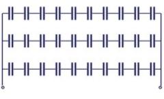
The diagram shows strings of 10 caps in series, and 3 of these in parralel.
Hi.
I haven’t a very good understanding of capacitors so I’ll ask. Is there any way that you could provide me with a diagram or schematic of how you built your MMC. If not, could you tell me what capacitors you used
The capacitor was made from lots of smaller ones joined together in series and parallel combinations. Its total was 15.18 nF and 20kV.
I’m not quite sure how you have made your secondary, but I think thousands of turns may be too many. There was around 850 in this coil, and I have also been able to to drive coils about half that size without changing any other components.
All circuits will have some resistance, capacitance and inductance, deliberate or not. It is often labled as ‘parasitic’ if it is not deliberate. For a Tesla Coil most consideration is given to the inductance and capacitance values. In the primary circuit, thick wires are used so that the resistance of these does not reduce the current flow. In the secondary coil a long thin wire is used, so the resistance is much higher, but this resistance is not very significant in comparison to the reactance.
The resonant frequency of a TC is determined by the product or inductance, resistance, and capacitance (LRC). Both the inductance (L) and the capcitance (C) are ‘storage vessels’ for energy. The capacitance stores energy in an electric field, while the inductance stores energy in a magnetic field.
When the spark gap first fires, the energy in the primary capacitor is dumped into the primary coil which stores the energy in a magnetic field. When the capacitor is empty, the current will stop flowing, causing the magnetic field to collapse. As it collapses a current is induced back into the coil (in the other direction) which then charges the capacitor again.
The time taken for this cycle is calculated from the LRC values, but we can ignore R because it is very small. Bigger values for L and C mean it takes longer for the energy to move around, therfore resonating at a lower frequency.
The secondary coil also takes some of the energy from the magnetic field collapsing around the primary coil. This larger coil has a much higher inductance (L) and it also has a small amount of parasitic / self capacitance (C). Again the resonant frequency of this coil is a product of LRC. In the secondary, L is large and C is small, but in the primary, L is small and C is large.
If the frequencies of the two LRC circuits match, then energy can be effectivley transfered between the two. The initial store of energy is in the large primary capacitor, but we are transfering this energy into the tiny self capcitance of the secondary coil and its sphere. For the laws of conservation of energy to hold true, the voltge in this smaller capacitance has to be proportionaly higher.
This probably all sounds complex, but you can get a TC to work without calculating all these factors as long as you are able to tune part of it. The LRC and frequency of the secondary coil are pretty much fixed, so it is common to tune the primary circuit to match this. Increasing L, R or C will decrease the frequency of that circuit.
and i came up with a cleva idea for a spark gap i have two screws mounted over a cooling fan but the screws are tied on copper which was wraped around a pen to get a coil.
Yes, HV can be very dangerous. Double and triple check that there are no live connections or charged capacitors before touching your circuit. Its also a good idea to avoid touching a different part of the circuit with each hand. This helps reduce the chance of getting an electric current to flow between your arms and across the heart.
I’m not too sure about microwave oven caps. If they can handle the voltage then I assume they will be ok. It may be easier to use several smaller ones so you can make smaller adjustments.
Yes you can twist wires together to increase the current handling capacity.
would you suggest that i start with microwave capacitors or somthing smaller also it i didnt have the right size copper could i twist together smaller strands to make the primary thicker i would think it would work?
thanks for helping when i get it working ill post on my web page
thank i just need to know this stuff because when working with high voltage there arent amny second chances
A TV flyback may work if it is large enough. The same applies for ignition coils. For the design shown on this page it was neccesary to use two ignition coils in parallel.
The simplest way for adjusting the capacitance is to just buy/make several capacitors that are rated for the correct voltage, then connect them in parralel. You can then add or remove a capacitor to adjust the capacitance. You will probably still need to move the clip on the primary coil to get fine tuning. The caps can be any type as long as they can withstand the voltage they will be exposed to. Use thick wire between the capacitor, spark gap, and primary coil for better efficiency.
The circuit diagram on this page is just a simple ignition coil driver with no spike protection. The ignition coil driver is used to charge the primary tank capacitor.
This thread in our forum may be useful. Unfortunatley the forum is closed for new members now because of constant spam. It may get removed alltogether.
hey iv worked out a simple technique for tuning the primary. im planning on just sliding a clip 1 cm around the long primary till i find resonance. i have a few questions though
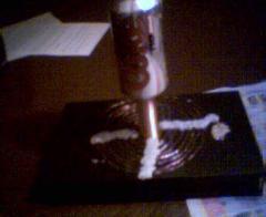
1 would a tv fly back circuit be suitable for the power source or enven a ignition coil?
2for tuning frequency of ossilations would a series of capcitors be better or different size compacitors?
3 can the compacitor be dialetric or a laten jar design?
and last but the least is your circuit diagram at the top for protecting spikes in ossilations rather than the frequency circuit its self?
Resistance effects are negligible, but the inductace is important as this will partly determine the frequency. The frequency is absoloutly crucial. If the resonant frequency of the primary and secondary circuits do not match, then you will not be able to transfer the energy properly.
You could try diferent numbers of turns, or different sized capacitors in the primary circuit. Try starting with a larger number of primary turns (maybe 20), then reduce by 1 turn at a time untill you see some results.
This still may not work if your frequencys are really far off. You could try using the Tesla Coil Tuner to match your circuits.
i built this mini tesla coil but need some info
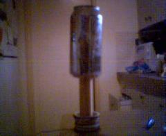
would the primary coil have to have the same electrical resistance as the secondary ? by this i mean secondary windings = more resistance . is this why there is lesser primary widings?
the copper i have is ‘secondary windings’= 0.5mm 2000 windings and the primary = 1 mm 5 windings
and would the frequency of ossilations matter
1) Butane was chosen to make the flame as it is commonly available lighter gas. Other flammable gasses would have similar effects. Other non flammable gasses were used and they created some fantastic plasma images.
2)Depends upon the battery size!:) It can draw aroun 5A @ 12V so if the SLA battery was like this one (7Ah) it would last about 40 mins non stop.
2 questions…
1) Is there any reason why you chose Butane for the gas? Are there any other gases that would also create effects?
2) How long would one of these as built on this site run on 1 battery?
If you do this indoors, be sure the ceiling is at least six feet above the top of the coil. I built a Jacob’s ladder (similar). One arc kept going up and set the cork panel ceiling on fire. Old commercial fluorescent sign transformers work great for either Tesla or Jacobs Ladders. They usually fail by the secondary shorting to the case. They are still useful but you now have to insulate the entire transformer. Putting them in wooden boxes works. Sign companies throw them out. A dozen wired in series will generate 200 kilovolts, or more, at a very low current. I put fifty in series and drew an arc that could be heard for a mile when it would snap off the top of the Jacob’s Ladder rods. I’d stop whenever I’d see the police cruising looking for the source of a bang louder than a shotgun. Be sure to wear heavy gloves, rubber sole shoes and welder glasses plus stand behind a safety panel if possible. I only had to set myself on fire once to learn “safety first”.
You are correct. A sharper point will cause a higher concentration of the electric field lines.
The breakdown voltage of air is often stated as around 10kV/cm. This is a rough value because the density, humidity, etc vary and can effect the outcome. The value given refers to the elctric field in a reigion of space rather than the voltage between two terminals.
I am making a similar coil. It is powered by a fixed-frequency 555 timer pulsing squarewave into a 2N3055. This turns 12 volts on/off into an ignition coil. The device is truly a work of art. My question though: I can generate about 2.5 inch sparks( at around 6 bps) to my finger, but only .5 inch sparks to the back of my hand(flat). Is this difference in spark production the result of sharper objects(finger), and higher field stresses?
The ignition coils are driven with a variable frequency source. Optimum power throughput seems to be around mid-high audio frequency.
This uses a spark gap made from a few sections of brass tube.
At what frequency are you running the ignition coils? And is this coil a standard single spark gap coil, or something else? Thanks.
To measure the voltage output you could use a voltage divider made from a string of very high ohm resistors and a lower valued one. You could then measure a portion the voltage with a standard multimeter / voltmeter then calculate the total.
The current can be calculated in a similar way. If the HV output is shorted with a low ohm, high power resistor, the small voltage measured between its terminals can be used with ohms law to calculate the current flow.
The HV output from the ignition coils in this example was rectified with a full bridge rectifier arangement of HV diodes. You can see how they were connected on the Power Pulse Generator page.
When using ignition coils it is most effective to fully rectify the output. This is because the output is pulsed and more +ve than -ve. Mains powered Tesla Coils use proper AC which has enough current to charge the tank capacitor on each half cycle (e.g. UK Mais frequency = 50Hz, Cap gets charged 100 times per second but with alternating polarity.)
I have two questions about this coil.
1. How can you calculate/measure the output characteristics of an ignition coil esp. it’s current and voltage. I have estimated my single ignition coil puts out about 15kv using spark length as a rough guide. And, using the transformer equation calculated the current was a tiny 0.5mA. Do you know a better way to ascertain the current output?
Is the high voltage output of the coils rectified using a string of high voltage diodes, if so how should they be connected to the circuit, which way round the cathode/anode etc?
Is it necessary for the output to be rectified before applying to the tank capacitor (MMC)I dont really know.
You can drive a preamplifying transistor such as a BFY51 by connecting a 100 ohm resistor between the output of the 393 and the base pin of the BFY51. This can then be used to drive your array of 2n3055’s like shown in the 1st digram on the Ignition coil driver page.
I `m Back :-)..
I had put this project on hold Several weeks ago due to a fairly heavy cold, an email asking for advice with another coil awoke my interest in a 12 volt system again.
I have mounted 7x2n3055`s onto a heatsink that was given to me ( overkill but, it was free ).. Now i need to connect to a signal generator.
I made the Power pulser from this website which works very well.
Is there a simple way to drive the 2N3055`s with that circuit.
Using my 3inch coil powered from the pulser I am able to draw a spark of about 25mm, in low light the corona is visible at the top of the coil.
More turns means more inductance, but this is totally unrelated to the power output you can achive.
The inductance of the coils simply determines the frequncy at which they will resonate.
e.g. A large inductance in parallel with a small capacitor (secondary coil and top sphere) will have the same resonant frequency as a small inductance in parallel with a large capacitor (primary coil and MMC or pulse capacitor)
thanx but would more turns mean more induction and there for more power? i need all the facts first
Yes it should be plastic or any other non conductive material.
The length of wire needed depends upon all the other components used to make the tesla coil. It is usually several hundred turns.
when making a tela coil should the pipe its wound onto be plastic and how much copper wire would be needed because you can get heaps from an ignition coil
Most of the information you require is allready on this website.
On the Tesla Coil Page you can find a diagram of how the coils and capcitors are connected, and a description of how the system works.
The primary coil is usualy a flat or conical coil with widley spaced windings like the one shown on this page. The centre of this coil is where the secondary coil is placed.
The secondary coil is wound around a plastic tube. It uses thin enamel coated wire (aka magnet wire) wound tightly for hundreds of turns down the length of the tube.
The 555 timer is used in the circuit for making a high voltage DC supply to power the tesla coil from batteries. You can see schemaitcs for the 555 circuits on the PWM Signal Generator page. This 555 circuit is used to drive transformers for stepping up the battery voltage to one high enough for the spark gap to work. You can see circuits for that on the Pulse Controler page, the Power pulse genrator page, and the ignition coil driver page.
The tank capacitor in this coil was 15nF @ 20kV which was made by linking smaller capactors together. You can see the electonics section to learn about connecting capacitors together.
Can you please tell me hwo to wire the primary and secondary coil. Where do they go and where do i put them. Also can you tell me how and where to put in the 555timer which legs do i use of that. Also what kind of capacitors did you use such as the voltage rating and the rating and how many. Thank you fo all your help.
Thanks again,
Stephen
Making the coils and putting it together was quite straight forward, but making an effective driving circuit was a little tricky as transistors are easily destroyed when used in HV circuits.
It looks really easy. Was it hard to make? We are working on a larger model in my class. I like the little light show, though, from yours.
60 Amps is way more than enough to kill you. You can be killed with a thousand times less current than that.
Arc welders use a low voltage output so that you only get high current when it strikes low resistance materials like metal. Using ohms law you can see that there is not enough voltage to cause a large current to flow in a person.
A MOT is a super dangerous transformer. It puts out around 2kV and is able to deliver a lot of current. Don’t use them.
im worried about the amps because only 60 will kill you but 100 thats out of the question and would advise people not to try this with microwave oven transformers as this comes close it only takes 2 seconds and your dead
It is strongly recommended that you DO NOT use mains to drive a Tesla coil! The plasma generated could arc unexpectedly to any surrounding objects (including yourself). Also, the power generated is lethal. Using a battery source limits the total amount of energy it is possible to create (the mains supply is limited by the power generating capacity of a power station!)
with a tesler coil how much coil would be needed and could you run it on ac from you houses power points all i have at the moment is microwave oven transformers
Running on 24V from a set of fully charged batteries, this setup could produce arcs of about 20cm to a grounded terminal. This could be increased to over 25cm when the flame was used
Type your message here
Thank you for reply and sorry here is an other question: what is a maxim. length of sparks ?
The capacitance of the MMC used for this Tesla Coil was 15.18 nF