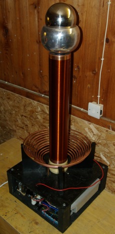
DIY SRSG Tesla Coil
with synchronous rotary spark gap
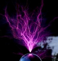
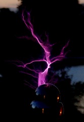 This Tesla coil runs from a 220V mains input at around 1kW to give an awesome display of arcs and sparks. It has been made with a large secondary coil so that the topload has sufficient elevation for some of the experiments it will be used for and so that it can be upgraded to higher power levels in the future.
The content of this page is for anyone with an interest in Tesla coils and high voltage. We have tried to explain everything clearly and with enough detail so that it can be understood by anyone with some basic knowledge of electronics. We have also included useful formulae and the calculated result of them based on the parameters of this Tesla Coil. Based on the information on this page you should be able to reproduce your own home made Tesla Coil (at your own risk) so there is no need to buy any Tesla coil plans when you can get free Tesla Coil plans here! There are also other more technical details included on this page so that it is still of interest to those who are already familiar with building Tesla coils.
If you are not familiar with Tesla Coils, you could read our page that describes how a Tesla coil works.
![]()
WARNING: Tesla Coils are very dangerous high voltage devices!
If you do decide to build a Tesla coil or use any of this information, you should make sure you understand all the safety precautions needed. RMCybernetics are not responsible for anything you do as a result of reading this information.

 |
Input Voltage | 220V AC |
| Power Consumption | 1000W Max | |
| Max Arc Length | 74cm | |
| Capacitor | 20kV 0.06uF | |
| Spark Gap | SRSG(100BPS) | |
| Primary Turns | 3.5(Tuned) – 10 Available | |
| Secondary Turns | 550(0.56mm wire) | |
| Secondary Height | 61cm(Windings only) | |
| Secondary Diametery | 11cm | |
| Topload | Double Sphere | |
| Special Features | Secondary Gas Feed |
So what does a SRSG Tesla Coil do?
A Tesla Coil is used to convert relatively low voltage (like from the mains) to a very high voltage which oscillates at very high frequency. The result of this is lightening like electrical discharges from the top of the device. SRSG stands for Synchronous Rotary Spark Gap. This term describes the way in which the power is switched in the Tesla Coil. These devices were invented over 100 years ago which was before modern semiconductors and electronics. This meant that to switch power it was necessary to use mechanical methods like the SRSG.
This SRSG consists of two stationary electrodes and four interconnected electrodes on a spinning wheel. As the wheel spins, the electrodes pass by the stationary ones which briefly allows a spark to jump and transfer some power. This happens repeatedly as the wheel spins around.
The motor used to spin the wheel is a synchronous motor which means that it spins in phase with the mains frequency. In the UK this frequency is 50Hz which will cause the motor used here to turn 25 times per second.
The capacitor used in this Tesla Coil will be charged 100 times per second so we want the spark gap to switch the power every time the capacitor is charged. Having four electrodes on the wheel means that at every quarter turn of the motor, the electrodes line up and allow the energy transfer.
 |
 |
 |
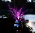
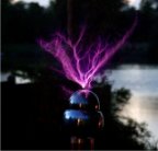
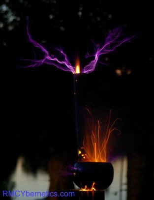
The photos above show the coil running at about 500W
Here you can see an arc hitting a grounded rod about 70cm away. The coil is running at 1kVA.
A long breakout point was needed to get good arcs due to the small topload
The parts used and what they do
Housing
For holding the components together
 The supports for the coils were made on a piece of wood which was dried and sealed before use. Even very dry wood can attract high voltage discharge to it, so it is important that it is kept very dry and sealed to prevent it from absorbing more moisture. Plastic is much better to use but can be expensive and harder to work with.
The supports for the primary coil were made by drilling a series of holes diagonally at equal distances in a block of wood. This was then cut down the center of the holes so that a series of grooves remain where the copper pipe of the primary coil would sit. These supports must be very well dried and varnished as the copper pipe could leak power into the wood.
The Grey pipe in the center is part of a 90 degree bend that fits into the push fit base of the secondary coil. This allows it to be mounted securely and easily.
Primary Transformer
Used to change the 220V mains input into 10,000V
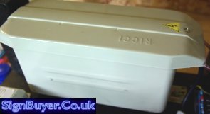
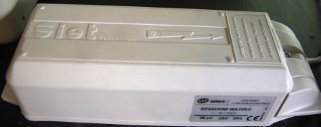
The transformer used is a Ricci NST (Neon Sign Transformer) rated for 10kV 100mA from Signbuyer.co.uk. This transformer is quite compact and comes with built in ground fault protection (GFP). There are a wide range of neon sign transformers available from Signbuyer which would allow you to make Tesla coils like this one or smaller. If you want bigger sparks, you can use two transformers in parallel to double the output power.
The primary transformer is what will determine the input power (and therefore arc size) to the Tesla coil. 10kV 100mA gives a maximum of 1kVA. (VA is equivalent to Watts, but is used because things get a little more complex with transformers). You can calculate the approximate size of arcs you can expect from the Tesla coil based on the input power. The length calculated is the straight line distance is that measured between the arcs origin on topload to a nearby grounded object.
Arc Length
L(cm)= 4.3 x √P(VA) = 136cm
This formula assumes that all the power from the input is transferred to the arcs and is not wasted in the conversion process. In practice this is not possible but the value given by this formula is a good guide.
 Based on the NST used in this coil the arcs theoretical limit is 136cm. The actual length we have got so far is 74cm. It may be possible to get more by having a tighter coupling between the primary and secondary coils but this would run the risk of causing damaging arcs between the coils.
NST’s have a small gap in the metal core which is used to limit the output current. This means that even with the output shorted, it wont overheat. Gapped transformers like these ideally should have a power factor correction (PFC) capacitor placed in parallel with its input. This serves to correct the shift in the phase of voltage and current caused by the large inductance of the transformer. It will work fine without it, but the power transfer will not be so efficient. The correct PFC capacitor can be calculated as follows.
PFC Capacitance
C = P/(2 x π x f (V2)) = 65.8uF
Where P = NST VA rating, V = NST input voltage, and f = mains frequency. It is not necessary to use the exact capacitance calculated, something less is fine.
It is common for people to remove the GFP when using the NST in a Tesla coil as the transformer is not connected to the mains earth anyway. It was left in for this coil as it can help prevent the transformer from becoming damaged if anything goes wrong.
 High Voltage Filter
Used to protect the primary transformer from damage cause by RF (high frequency) voltage spikes
The filter used is a common type of low pass filter known as a Terry filter which is often used in Tesla coils which are powered from an NST. The filter allows the 50Hz mains frequency to pass through easily but will provide a path to ground for the high frequency currents. It also includes a set of MOV’s which will short to ground if the voltage gets too high.
Resistors are mounted on heatsinks as they will get hot when in use. These and the other components must be spaced apart adequately so that sparks don’t occur between them.
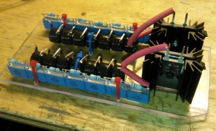
To protect the 10kV NST used in this Tesla Coil, we used 14 of each of the following components; MOV/TVS – 1800V, Capacitors 1.6kv 3.3nF, Resistors 10M ohms 0.5W. In addition to these two 1k ohm, 100W resistors mounted on heatsinks are used. You can see how these are connected together in this Terry Filter Schematic. The the main schematics lower down to see how it is connected in the system.
Primary Capacitor
Used to store energy for releasing in pulses into the primary coil
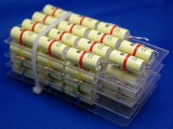
 With smaller battery powered Tesla coils the type of capacitor used is not too important. With larger coils like this it is important to use high voltage capacitors that are suitably constructed for handling large amounts of power. Large ones like shown below can be quite expensive so it is common to construct an equivalent capacitor from lots of smaller ones. This is known as an MMC. The one shown here was made by connecting fourteen 1500V 47nF polypropylene capacitors in series, then making 3 more identical strings. Each of these strings is equivalent to a 21kV 3.4nF capacitor. Connecting these four in parallel makes the overall capacitance 13.4nF. Usually a 10M resistor is placed across each of the small capacitors as a safety precaution. This capacitor was not used as it was too small for the NST.
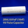
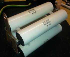
The primary capacitor used was made by combining six 20kV 0.01uF pulse capacitors in parallel. This capacitance is about as large as the 100mA NST can charge between each firing of the spark gap. With a static gap this capacitor would need to be smaller, but because the spark gap used here is synchronous, a larger capacitor is possible.
The value of capacitance that will work best with the transformer is calculated based on the mains frequency and the transformers impedance. You can calculate the transformers output impedance based on its output ratings
NST Output Impedance
Z(ohms)= E / I = 100k ohms
Where E = NST Output Voltage and I = NST Output Current
Now we know the output impedance of the NST we can calculate its capacitive reactance. The capacitive reactance give us the value of capacitor that the NST can fully charge during each half cycle.
Primary Resonant Capacitance
C(r) = (1/(2 x π x Z x f)) = 31.8nF
Using a capacitor that matches the capacitive reactance of the NST is not recommended. This would cause a resonant condition that would cause the voltage to rise, possibly damaging the NST and the capacitor. This is not the case for other types of transformer, but for the NST you would use a larger capacitor to prevent this resonant condition occurring. The actual value depends upon the type of spark gap used and is calculated as follows;
Actual Optimum Capacitance
Static Spark Gap:
C = C(r) x 1.618
Synchronous Rotary Spark Gap:
C = C(r) x 1.9 = 60.47nF
Where C(r) = the calculated resonant capacitance or capacitive reactance.
The capacitance of this capacitor combined with the inductance of the primary coil will determine the resonant frequency of the primary circuit. It is essential that this frequency matches the resonant frequency of the secondary coil so that energy can be efficiently transferred between the two and the voltage rise can occur.
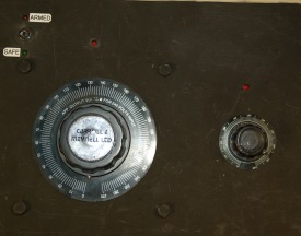
Spark Gap
Used to discharge the capacitor into the primary coil by making and breaking a connection like a switch
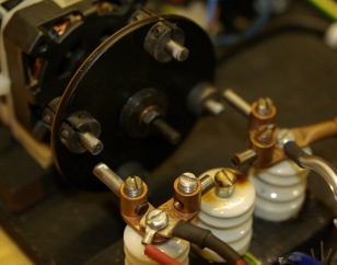 The spark gap used here is a synchronous rotary spark gap. This means that a motor spins around, moving some connected electrodes past the two main electrodes so that it will make a connection as it passes and break it again as it moves away. The spark still needs to jump but it is just about 1 or 2mm. The motor turns around exactly 25 times per second and is in phase with the 50Hz mains current. The four electrodes fixed on the rotating wheel are electrically connected and will connect the capacitor to the primary coil 100 times per second. The position of the rotating electrodes must match perfectly with the mains frequency so that the connection occurs when the capacitor is fully charged (at the peak of each positive or negative half cycle). An external control was made for controlling the phase of the motor so that it can be matched for optimum performance when it is running.
Also included is a safety gap which is just some electrodes spaced at a set distance that will allow the capacitor to discharge into the primary coil if the for some reason the rotary gap is not working right. When the motors phase is matched exactly or is slightly ahead of the primary capacitors voltage the safety gap should not be firing.
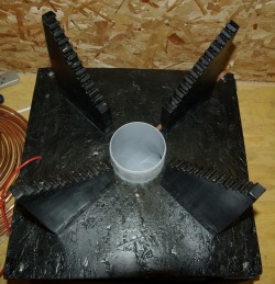
Primary Coil
Used to transfer energy to the secondary coil from the primary capacitor
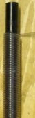
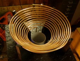 The coil is made from standard 6mm copper plumbing pipe. This is quite soft so it is easy to wind into a coil shape.
Copper pipe is used because it is thick and has low resistance (more efficient) and it is also easy to clip a wire to different points around the coil when tuning.
Wood should be dried and sealed as the copper pipe will be at high voltage when running the coil. The 10kV present on the coil is enough to jump to any unsealed wood which could cause fire or just hinder the coils performance.
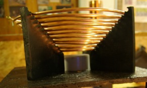 The coil was wound in a conical shape to allow for a good coupling to the secondary coil. If the power is upgraded in future it would be necessary to add a grounded strike rail above this to protect it from being hit by the Tesla coils output. It may even be necessary to replace the coil with one of a flatter design.
Secondary Coil
Used to step the voltage up higher still so that arcs can be produced from the topload
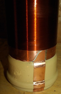
 The secondary coil was wound on a piece of standard 11cm diameter waste pipe. This piece had a push fit type connection at one end which would be used to mount the coil on the Tesla coils base.
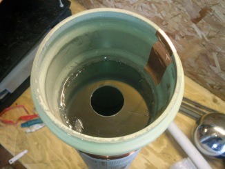
Each end of the coil was terminated with a final winding made from copper tape for neatness and easy connection. This loop of tape should not be continuous as it would act like a shorted turn and waste energy. A small cut is made so that the copper tape acts like the final turn of the coil connecting the wire to the RF ground.
At the base of the coil, the connection for RF ground is made by taking a strip of copper tape down the side and a few cm up again inside the pipe. When this end is pushed onto the support it meets with a matching area of copper which is connected to the RF ground This makes it very easy to place the secondary onto the base and have the RF ground connected without any solder or screw connection .
The same method is used for connecting the coil to the topload.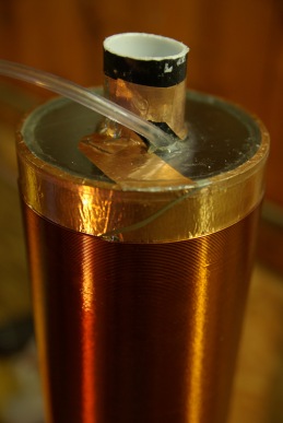
 Because this is an RMCybernetics Tesla Coil, we like to do it a little differently. Down the center of the secondary coil is a piece of 32mm drainage pipe. it is held in place by plastic discs which are epoxied in place. Around this central pipe is another pipe that is wound as a coil along its length. This pipe is about 20m long when uncoiled.
These pipes can be used for piping gasses or mechanical systems to the topload for performing various interesting experiments.
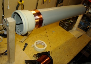
The secondary coil was wound on a simple jig with a geared motor at one end attached to a motor speed controller so that it could rotate slowly. The speed controller (our PWM-OCX) was linked to a foot pedal switch made from some wood and a microswitch. This allowed for the rotation to be started and stopped easily while keeping hands free for holding the wire.
When winding the coil it should be kept clean and the wire must be kept tight so that no kinks occur. After winding it was coated with polyurethane varnish to protect it from physical damage and to reduce the risk of the arcs flashing over the windings.
Topload
Used to store energy and to provide a place for sparks to come from
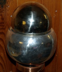 The topload is made using two separate spheres. The larger one is an upturned metal dome used in Van De Graff generators while the smaller one is a ‘floating sphere’ from a local DIY store. The smaller sphere has had a brass pipe fitted through the center so that it can be connected to the coiled pipe mentioned earlier. This sphere is just placed on the larger one which gives easy access to the pipes when changing experiments.
 The size of the topload will have an effect on the resonant frequency of the Tesla Coil. With the topload as shown the secondary coil had a resonant frequency of around 435kHz. Removing the small sphere makes it 455kHz and having no topload makes it 570kHz
A larger topload will give the secondary coil a lower resonant frequency and will also make it harder for a spark to break out. This allows the arcs to be larger than they would be if no topload were present.
Sometimes if a large topload is needed to get the right resonant frequency, a small point such as a metal rod or screw can be placed somewhere pointing outwards. This is known as a breakout point and will cause the sparks to come out at the end of it. This occurs because the point will have a large electric field gradient compared to the smooth round surface elsewhere.
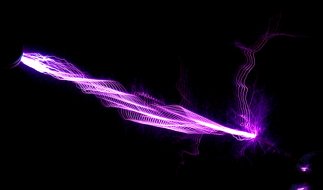
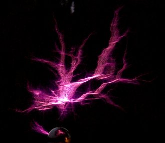
When we upped the power from 500kVA to 1kVA steamers came from all over the surface of the topload. In order to get them to come from one place and be larger, a breakout of about 20cm was used.
 Control Box
The control box houses the two variac’s, a 120V transformer, a power relay, RFI filter, and a key operated switch.
The large variac is rated for 10A which is more than enough for the transformer used here. This variac allows a simple adjustment of the input voltage to the NST from 0V to 270V. The smaller variac is used to control the phase angle of the motor for the rotary spark gap. This allows for the timing of the capacitors discharge to be adjusted to match perfectly while the Tesla coil is operational.
Circuit Diagram
The diagram below shows the main tesla coil system components. The Terry filter is shown in simplified form in this diagram. The input to the circuit is 220V AV at 50Hz which is standard UK mains. This is first fed directly into an RFI Filter before then going to a large 10A Variac (T3). This variac allows the input voltage to the NST (T4) to be varied from 0 to 270V.
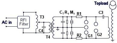
Only the RFI filter is connected to mains earth. The terry filter, NST, and secondary coil are connected to RF ground. The RF ground is made by forcing a large copper plated iron rod into the earth near the coil.
CT RT , MT, R1 and R2 are parts of the terry filter described earlier. In addition to this filter, a safety spark gap (G1) is used which will fire if the voltage is too high.
The main electrodes of the rotary spark gap ar. shown as G1 and connect to the main tank capacitor (C3) and the primary coil.
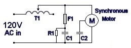 This diagram shows how the motor is wired to a variac for electronic phase control. This really makes things a lot easier to get the coil running well. A small variac (T1) passes power to the synchronous motor. The inductance of the variac combined with the capacitance C1 will allow small adjustments in phase of the synchronous motor. It is necessary to turn the variac to maximum to start the motor and allow it to lock on to mains frequency. It can then be turned back about 1/4 of a turn to adjust phase by about 25 degrees before the motor looses lock.
Experiments
The video below shows our first attempt at launching a rocket from the topload of the Tesla coil while it is running. The video is not great as we were a little afraid!
 To launch the rocket, a remote trigger for igniting the fuse was needed. This was made by using a home made air operated switch that connects a 12V battery to a 10 ohm resistor. The resistor heats up quickly and ignites the rockets fuse. The battery, switch, and resistor must all be contained within the topload sphere as they will be protected from the high frequency, high voltage. The airline passes down the inside of the secondary and out to a large syringe near the control box. When the syringe is pressed, the switch activates and the rocket launches.
So far we have only had one try at this as we can only do it when the weather is good. It is quite difficult to get a get photo of the rocket as it exits at high speed. We will need to do this experiment several times to get some god shots. In the photo above there is a large foil lined tube which contains the rocket. You can see as the rocket starts, the flames are leaking in various places. We will need to make a special topload for doing this again as to avoid damaging the coil.


Hi,
Really cool project and very well documented in fact I did learn few thinks from it 🙂
8mm sparks from a 10kV NST seems quite normal.
Hi, I starting to build a tesla coil. I got a used nst from a city around here, but since the shipping would be a fortune the guy only sent me the transformer without the metal case. He asked me if I would plug it in 110 or 220v. I said 110, so he wired it to "110v". But the sparks are way too small. Like ~1/3 inch maximum, or 8mm. I think he wired it to 220. And it gets "worst" as the primary coil has 5 wires. 1 brown or black, 1 white, 2 blue and 1 red. Both blue are soldered together, white and black goes to wall socket and red is isolated. I have been measuring some combinations with my multimeter, but I’m afraid to try them and burn the thing. A new nst here is 200$…
Perhaps a couple of weekends. The coil winding and varnishing is time consuming. Tuning it for top performance would also take a while.
if i order from RMCybernetics and i live in the US. and I decide to build the Tesla Coil, how long will it take for a begginer with supervision to build?
Yes they do have built in GFI, but it is just a module screwed inside and is easily removed. I left it in place in this Telsa Coil and it rarely trips out.
Hello!
I’m interested to know whether the Ricci NST you’re using has a GFI circuit (ground fault interrupter).
My understanding is that a NST with GFI is not ideal for a Tesla coil.
Do the Ricci NSTs currentlay available from http://www.signbuyer.co.uk have GFI and if so are they still suitable for powering a Tesla coil?
Thanks,
Tim
Hello with all, With a transformer for tubes NEON (NST) and a mini multi capacitor (M.M.C), Then I to make an successful experience of COLD FUSION ” COLD FUSION ” is the name given by jl. NAUDIN with this phenomenon: a noisy electric arc between two electrodes (tungsten and stainless) thank you
Yes, you should still use the filter. I would think that this transformer is almost the same as your NST so you could use the same parts.
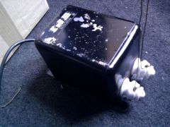
hi thanks for that info,my coil seems to be working correctly and has a better output with 1.6x ressonant value caps,i have used 2x 0.025uf 10kv teflon ceramic doorknob capacitors in series,seems to work great.i have recently acuired a new transformer,it is rated 2x5kv @23ma.it is aparently an old radar transformer?iv included a pic of it.the arcs are very much like my nst arcs which is very simlar specs at 2x5kv @25ma. i cant find any info on the radar transformer but suspect it might be a nst.what i want to ask is will i need a terry filter with this kind of transformer and if so can i use the one i allready have which is set up fpr 10kv @25ma? thankyou..
It certainly seems like you are suffering from a resonant voltage rise. You should make your capacitor 1.6 times larger than the calculated resonant value.
The capacitors need to be rated for pulse discharges as the internal forces can be quite high.
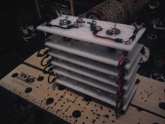
my mmc uses 4kv 3300pf PETP capacitors,they are cheap russian ones from ebay as funds are low at the moment.i have 12 strings of 5 caps to give 20kv @ 7920pf.i used a free online program which told me that 7900pf was optimum for use with my ricci 10kv 25ma nst.although 20kv @ 7920pf was the closest i could get with the caps available.could it be that the program i used has given me a capacitance value which is resonant to the nst?.im thinking of going a little higher next time to 8000pf im not sure if this will help? could you recomend any good capacitors for the job? and any bad ones to avoid?.iv added a pic of my mmc,i dont think configuration has anything to do with my problem but it has 6 chopping board plates in parralel each containig 2 paralel strings of 5 caps in series.it has a safety gap on top.when the capacitor bank blows it always takes out 5 caps at a time,one whole string.it went with a very loud bang and a flash the first time but the past 3 times it just stopped running after around 8-20 seconds.any help apreciated.thankyou..
The steamers are always purple unless they strike ground. The colour is only white when a high current flows. I would thing the youtube vids may look more white just because of the way the camera is working.
If you are getting lots of streamers at the same time, try using a breakout point like in the article. This made a good difference to the length of the arcs as all the energy becomes concentrated in one arc.
Sphere’s or toroids will work fine. Toroids are generally preferred because the move the output further from the coil and reduce the risk of it striking its self.
Tell me more about the ratings and configuration of your MMC.
Salt water caps are not very efficient as glass is a lossy dielectric at high frequency.
hi there,i have recently biult a 2.5″ coil that runs on a 10kv 25ma nst,after some tuning and the fire alarms in my biulding mysteriously going of during coil runs,im getting lots of streamers to air ranging from tiny ones to 8-10″ but usualy lots at a time with a 12cm stainless spherical topload and they are very purple in colour like the ones your coil is producing and seem to be realy floaty and high frequency looking.my goal is to get the long white looking “lightening” like in most tc vids on youtube.do i need a bigger topload to accomplish this? and does it need to be toroidial in shape? also after fitting a terry filter my mmc bank keeps blowing? its rated at 20kv and 7900pf,could the filter be in some way responsible for this? the cap bank has a safety gap but this does not fire when the terry filter is in use,nor does the terry gap.i want to open my main static spark gap a bit more to see if it produces longer arcs but i think this will contribute to more cap exploding.my plan is to make a saltwater capacitor bank with the same capacitance value as my mmc and see how it performs then as i think the saltwater caps will be more robust,my question then is how high can i charge a cap without my nst getting killed? i have a safety gap on my terry filter,if i set this correctly and the main gap doesnt reach breakdown voltage(ie. open to wide)should this fire and protect my nst?.thankyou..
Not yet. We have these small Tesla coils, but they wont make big sparks in the air like this big one does. If you want something made for you, please send your requirements to us using the custom electronics application form.
any word on these smaller kits. how much would you charge to build a smaller on,
I got both the resistors and the MOVs from RS.
hi,where can i get some mov’s from? the 1800v type you have used in your terry filter,looks nice.im planning on using a white kitchen chopping board for mine with nst porcelin stand-offs and brass corona balls for the safety gap,having trouble sourcing the 1k 100w resistors and the movs tho.
Not at the moment. We will have some smaller Tesla Coil kits in the future
Any plans to make this a kit job?
I would stay at least 3m away from it.
How close can you get to that thing safley?