 A Multi-purpose power pulse generator capable of driving Tesla Coils and other high power coils. This device is based on the Homemade Tesla Coil project and uses an improved version of the ignition coil driver circuit to generate high voltages.
This unit quite simply can generate high current pulses of variable frequency and pulse width. This unit uses the Square wave frequency generator shown in the DIY Devices section for the main signal source but any other signal source can also be connected to it. The input signal is amplified using an array of nine 2N3055 power transistors (T2) which is capable of switching huge amounts of power.
| WARNING: High Voltage is used in this project! |
A switch allows power to be sent to external coils for low voltage applications, or the internal ignition coils can be powered for charging a large HV pulse discharge capacitor.
The low voltage circuit in this device is similar to the driver for the Homemade Tesla Coil, but with some important differences. The high current pulses from the Lead Acid Batteries makes the signal generator unstable in the original design. The new version uses a completely independent signal source with its own battery to minimize the interference. There is also an extra buffer circuit to protect the 2N3055 Transistors from voltage spikes caused by the inductive kickback from the auto ignition coils.
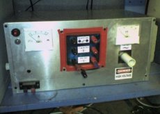
All the power electronics are housed in an Aluminum case finished with panel meters, IO ports, and switches. The signal generator circuit is housed in an independent unit with its own 9V battery. This can be connected to the main unit via a shielded cable allowing it to be operated from a safe distance.
The high voltage output from the ignition coils is rectified using some large high voltage diodes (D2) designed for X-Ray machines. The rectified output is connected to a large capacitor (C1) for smoothing the DC output. From the smoothing capacitor an inductor (L1) and an additional ‘de-Q-ing’ diode (D3) have been added to the charging circuit to block the AC ringing from the TC primary coil from reaching the the smoothing capacitor. These also help to protect the the rectifier from short circuits, arcing currents and possible back EMF or transients.


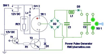
| SW1 | Low Voltage Selection Switch |
| SW2 | Lz |
| TR1 | Four Ignition Coils in Parallel |
| RC1 | Spike Filter |
| T1 | BFY 51 Transistor (Preamplifier) |
| T2 | 2n3055 (nine in parallel) |
| D1 | High Power Diode |
| D2 | High Voltage Rectifier |
| D3 | ‘de-Q-ing’ Diode |
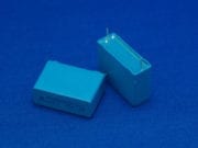
| C1 | High Voltage Smoothing Capacitor |
| C2 | Pulse Discharge Tank Capacitor |
| L1 | Homemade Inductor |
| SG1 | Variable Spark Gap |
| The connectors used here are just standard banana types. They are not designed for high voltage use and will therefore leak a little energy by ionising the air nearby. |
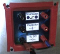 The main high voltage front panel on the box has sockets for HV DC output, an internal HV pulse discharge capacitor, and an internal spark gap. This allows the high voltage circuits to be configured in a number of different ways without having to re-wire any internal components.
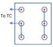 The image on the right shows how the panel is wired to drive a Tesla Coil. The spark gap can be adjusted using a handle on the side of the case. Depending upon the resonant frequency of the TC being driven, it may be necessary to adjust the capacitance. This can simply be done by adding more capacitors in parallel, or using a separate one.
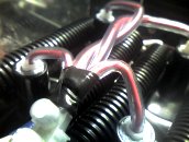 This image shows the interconnected outputs of the ignition coils. The ignition coils are wired in parallel to give a higher output current.
All the high voltage cabling inside the box is placed inside flexible plastic tubing for added insulation. You can see here that the low voltage connections to the ignition coils are also covered with tubing for added protection.
The case is grounded by connecting a thick wire to a long metal spike driven into the ground. All of the ground connections for the internal circuits are also connected to the case.
Connecting the case to the earth spike is essential when using the device to drive Tesla coils. This is because a Tesla Coil (TC) will generate radio frequency (RF) currents that would otherwise become present throughout the circuit. Without a good RF ground you would probably receive little shocks from the controls when operating a Tesla Coil.
Internal Variable Spark Gap
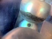 This new spark gap is made using three spherical electrodes in a high K dielectric casing. The double casing of the spark gap reduces the overall noise and allows the airflow to be doped with other gasses.The anode and cathode are spaced further than the voltage could jump and the third sphere can be moved in and out of the gap via a long glass fibre rod. This allows the spark gap to be adjusted smoothly anywhere between short and open circuit whilst it is active.
A pair of 12V DC brushless fans are installed to improve airflow through the spark gap. This is not to improve quenching, but it will reduce electrode corrosion from Ozone buildup in the spark gap casing. A further filtering capacitor has been added across the fans connectors as this type is sensitive to voltage spikes
Controls
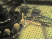 The control circuit used for generating the driving signal is made using a 555 based circuit. This circuit can be found on the DIY Devices Page and is titled Signal Generator with Pulse Width Control. This circuit is housed inside a small hand held box with a 9V battery. It can be connected to the Power Pulse Generator by a jack plug on the end of the cable from the unit. You can buy an advanced version of this signal source here.
Different ignition coils or transformers will have different resonant frequencies. Using this circuit allows the Ignition coils to be tuned and driven at their resonant frequency.
External transformers, coils, or solenoids can also be driven at any desired frequency within the range of the 555 timer. The pulse width modulation capabilities of the control circuit are used for power level control for transformers and other coils. This feature also allows large or small DC motors to be powered with variable speed between 0% and 100%. These can also be tuned to their resonant frequency.
This device is capable of powering a multitude of experiments and is great for any researcher experimenting with pulsed power or resonant applications. You can see experiments we have done with Tesla Coils using this device on the Tesla Coil Experiments page.


Hi
Thanks for this site.
What is the overall capacitance of C2 and its voltage tolerance?
Thanks
Giyora
The capacitor was around 11nF, 25kV made by connecting lots of smaller ones together.
We have large pulse capacitors available in our shop.
https://www.rmcybernetics.com/shop/electronic-components/capacitors/high-voltage-pulse-capacitor
Just a message to say the new site looks great and as always the DIY information is superb. I fully recomend the products on sale, they work a treat. All the best of stuff.
Getting a bit off topic here. You can limit the voltage using Zeners or MOVs.
Hi Richard,
The current booster circuitry that I’m interested in loosely mimicing is based on cuurent boosting circuitry found elsewhere on the net. The circuits seem to be based on the premise that the additional circuits would add additional current to the load after the limit has been met by the original controlling entity such as an LM7812.
A transistor, such as a TIP2955, has a resistor in series with it’s base, which is connected to the input to the LM7812. This resistor has a value of 10 times another resistor that is positioned in series with the input of the LM7812. The second resistor is in series with the input to the LM7812 in front of the connection to the larger resistor and the TIP2855 base.
The emitter of the TIP2855 is connected to the input to the LM7812 in front of the smaller value series resistor.
The collector of the TIP2855 is connected to the output of the LM7812; thus the TIP2855 is connected in parallel to the LM7812.
This is a described condition where the voltage through the LM7812’s output is controlled/reduced.
I’m dealing with a situation where the voltage is being boosted by a commercialy available boosted high voltage circuit with a very low amperage output. I need to increase the current to the load in the same manner as the previously described situation; except for one major difference. As you stated in your previous answer, the required result could be reached if it was a pulsed system using capacitor(s) as a voltage storage source — which is what I want to do. I will be pulsing the output ground as the control at around 20% of a set frequency, leaving the remaining time for recharging. I will be using two capacitors in parallel so that each individual capacitor will be supplying 1/2 of the total additional amperage. The question that I have now is what circuitry to use to protect the charging of the capacitors so that the high voltage unit doesn’t become toast in the process. The operational recharging doesn’t have me worried, it’s the initial charging sequence that I don’t know how to control.
I know that your pulse generator deals with large amounts of current, while my system is exacly the opposite; but any info you can send my way about safely charging these capacitors when the high voltage source, i.e., the high voltage boost circuitry, can only supply about 40 – 45r mA to the process. The two parallel capacitors are 200uF @ 150 vdc units; and any info you can send my way will be greatly appreciated.
Thanks in advance,
Richard
A MOSFET is a transistor. I’m assuming that you are talking about linear vs switch mode power regulation. If your power source is limited to 50mA then there is no way to get more than this in a linear way. If you are drawing power from the supply in pulses, then a large parallel capacitor might help with peak current as it will charge between pulses. The average current though will be the same. The other alternative would be to look into using a buck converter.
Hi Richard,
I think this is the proper section pertinent to my question, so here goes. Instead of maximum current as envisioned here; I need a 2 – 3 Amp current booster circuit to parallel my high voltage booster board with it’s 105 vdc out and 50 mA max output that I have cobbled together from your information here.
I’m thinking I need to have it operate so that it’s not a “demand” type of circuit (biased transistor controlled) but should be MOSFET controlled so that it can be driven, i.e., sequenced with another section controlling the operation of the load. I’ve got the high voltage section perfected to where I want it, but the current booster capacitor placement has me stymied. The “on time” needed is only about 1/6 -1/5 of a 61kHz. I have on hand 6 – 200uF/160 vdc electrolytic caps I think I can use as the rechargeable current booster source, and I think that because of low “on” time, they can be recharged during the 4/5 of the cycle that they won’t be needed.
What do you think, can you help me with this, and thanks for any help you can give me.
Richard
You can use a MOSFET instead of both T1 and T2. Just make sure it is rated for enough current and voltage. If the flyback has output diodes, then you wont need to add more.
Can I use a IRF710 or IRF510 Mosfet instead of the BFY51 for T1? Also can I use flyback transformer(s) instead of ignition coil(s), if so would it eliminate the need for the diodes because the flyback has a built in one? Thanks for your help and for everything you do, you are much appreciated.
The Tesla coil its self will determine the frequency, not the drive electronics.
Can this be used to run a TC at frequencies in the range of 13 MHz?
About 25mA short circuit current per coil with about 14V, 3A input.
hi,what would be the approximate current provided by an automotive ignition coil in this setup? i realise this will vary from difrent manufacturers but as a rough guide.and what would be the expected current from 4 of these in paralell like in the setup at the top of this page.i have 4 ducillier coils and want to run them between 12-24v.thankyou..
The kit is not available anymore
Type your message here
what is the difference betwen
PWMOC10A et PWMOC10A-kit
thanks
It would help, but bigger is better for a smoothing cap.
Can you give some more details about the smoothing capacitor – would a 30kV 1nF cap be enough?
Thanks.
Hello out there! I feel like I have been living in another world somewhere else for the last 53 years. GREAT stuff here! Can you or anyone else break down a schematic I found on another site that shows how to build a wide band fuel injector monitor? Or does some one out there have one to place on this site? With fuel prices where they are it would be a BIG help to many and would be nice to have a bit more control of what we as CONSUMERS paid for when we bought our vehicals in the first place. THANKS and Keep um-coming, YOU GUY’S ARRRRRE GEEEREAT!
here
I am looking for a diy high voltage generator (based on capacitors) circuit design — to be used as an insect killer?
D3 is another HV diode. There is nothing particularly special about it. It just needs to be rated for the expected voltage and current.
Type your message here
What is the Voltage rating of D3
Is this a special diode? Thanks for bearing with my query
Regards
Ralph
About 1A per transistor/coil is usually sufficient.
Just one final question: How many amps should D1 be rated for? Thanks in advance.
RC1 used was also 10k resistor and 0.1uF capacitor in series. The computer PSU would need to be able to deliver at least 5A for each ignition coil.
Nvm, I’m gonna use a .1uF Cap and a 10K Resistor. One more question though. Would it be alright to use a computer PSU as the power source as long as I plug it into a EMI filter. Thanks
What were your snubber values? I know they’re different depending on the coils, but I don’t know the output of mine, so I want to get a general idea as to what they would be.
Yes, the metal object placed inside the work coil of an induction heater acts like the short circuited secondary coil of a transformer.
is the m10 nut acting as a secondary and inducing high current whilst the work coil is like the primary? if so then all you need is a high current and high frequency power source like your ignition coil driver or a mot with a lot of turns for the work coil. if im wrong please tell me as any advice will help my project.
D2 is made from four 30kV 1A diodes.
If you meant you have a 40kV 1A bridge, then yes, this would be fine.
How high is the value of D2 in your schematic? Would a 40vK .1A Bridge work alright? Thanks.
You will be very satisfyed with the number of visitors that will come to your site if you give any plans how to build the induction heater so please hurry and you wont be dissapointed
Not at this time.
hello can u provide a fully step step guide to that
You need a high power, high frequency pulse circuit similar to this Power Pulse Controller. You would use it to switch a higher voltage source (200V for example) through the induction coil with a parallel tank capacitor and probably an impedance matching transformer. The frequency would need to be in the RF (Radio Frequency) range.
Can you give me any tips how to build an induction heater from your experience? is there any circuits here to help me? Thanks for replying
No. This would not be very efficient for induction heating.
Can we use this RF generator to produce a induction heating device? Is there any modifications to the circuit (component values, frequency?)
It could, but its not ideal. The Pulse Contoller would be best.
Can this curcit power the DIY supercooler
The google ads aound this page (and the other pages about High Voltage) should have some links to suppliers of HV diodes. The ads are geotargeted so they should give you the most relevant ads mased on the county you are in. If there are not any relevant ones showing today then Ebay does seem to have plenty available in the US and UK.
I’ve been trying to track down some high voltage diodes like you’ve used in the rectifier D2. Other than trying our luck on ebay, where are we able to get them from?
Thanks,
Chris
Yep, its a snubber. The exact values of your components may vary with your application and coil types.
I failed to find the specs on the spike filter.Could this be a snubber .. Thanks
R1 is just a 100 ohm resistor to limit the current through the BFY51.
C1 is a large capacitor used for smoothing the DC. The value is not critical, but larger is better.
C2 is the MMC for the tesla coil.
Type the part number for the diodes (or any component) into google and look for a link to a PDF datasheet. This will tell you everything about it.
Hey, I was looking at diodes and it seemd that thier ratings are “encoded”. How do I tell what the voltage and amperage is?
What About the capacitor and resistor in RC1 (I assume that is what is in it) and also R1 and C1
I assume C2 is the capacitor I built For the TC
Most components are the same as used in the DIY Tesla Coil.
HV Diodes in this one were made larger (30kV 0.5A)
Hey, could you give me the specs (voltage resistance, capacitance and the like) necessary for ordering the needed products. thx
You can buy tiny gas filled spark gaps that will trigger at around 90 Volts, but these are non adjustable. A similar device might be a varistor. These work in the same way as a spark gap but are made using diodle like materials. They are normally used for surge supression but you can get ones rated with low voltages. If the varistor can’t tollerate enough current then you could just use it to trigger another transistor.
I like to use the inductive kick voltage from an arc’s collapsing. As well as that from the coil. The overshoot pulses are unidirectional, since the arc always collapses on the same node. So I need to pulse the 12V supply with the SGsubPWM, then send the output current through an LV spark gap.
Do you mean to switch 12V pulses? I guess you would normally use a MOSFET or a TRIAC if ts AC.
I like the internal spark gap. Is there any way to make an adjustable component like this for 12 Volts?
You can also use this circuit as an inductive ground. Connect the TC ground to the positive bus between the ignition coils. It’s a single wire circuit which makes the spark a lot harder.
The ignition coils are wired so that all the same terminals are connected together as shown. This does not increase the output voltage like your ‘anti-parralel’ setup, but it will increase the current.
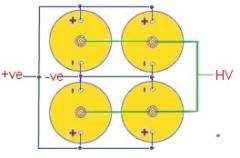
Type your message here : VERY INTERESTING PROJECT. I run my TC by using TWO ign.coils with their primaries in parallel (but the + on one is to the – on the other and vice versa). I am unable to make up how you can interconnect FOUR ignition coils (=four autotransformers). Pity that circuit diagram is missing. I would greatly appreciate it if you are able to take the time to explaim this interconnection in detail. Thank you. Joe Lovell, Sydney, Australia.
jozefau@aol.com
The value of L1 just needt to be enough to stop the very high frequency ringing from the prmary circuit in a TC setup.
In this device it was a simple home made inductor simply wrapped around a plastic tube about the length of a pen. This should provide enough inductance to block most of the high freqency, but is still low enough to let through everyhing else.
L1 value isn’t specified does it matter or will any inductance value work?