-
×
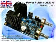
 Power Pulse Modulator - PWM-OCXi v3
1 × $145.88
Power Pulse Modulator - PWM-OCXi v3
1 × $145.88
Subtotal: $145.88
Power Pulse Modulator - PWM-OCXi v3
1 × $145.88 Subtotal: $145.88
This section gives details of many DIY science projects and equipment which can be made at home.
 DIY Sensor Multiplexer
This device was created to allow more analogue sensors to be added to a homemade robot. It is simply a 8 port switcher for analogue or digital signals. The device is controlled by a PIC 12F675 microcontroler, and gives eight analogue outputs from one analogue input, and one digital input.
The K8000 computer interface board, used on the robot, is limited to four analogue inputs. A multiplexer was essential in order to capture more sensor data. The multiplexer can allow the computer to capture data from several sensors using a single analogue input on the K8000.
To do this it was necessary to create a device that could switch eight digital outputs one at a time and be controlled by 1 digital input from K8000. This is very similar to ‘running lights’ where several LED’s run in sequence and start again. To keep the multiplexer small it was decided that a PIC microcontroler would be used, as this would greatly reduce the number of required components. The chosen PIC was the 12F675 because of its small size (8 pin) and the low cost of the chip programmer. This PIC has only four digital outputs so these also needed to be multiplexed. The digital outputs when low can be used like a ground connection, allowing LEDs to be connected directly across two outputs as shown below.
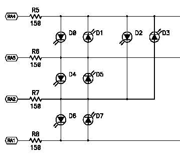
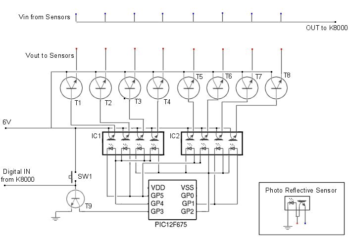
The diagram above shows how four outputs of a PIC can be used to control 8 LEDs. If these LEDs are inside an optoisolator then they can be used to trigger transistors, allowing a sensor to pass data to the computer. The diagram below is intended to show the connections of the sensor multiplexer. This diagram does not show some components such as resistors and capacitors, and is intended only as a guide.
To capture sensor data from the multiplexer a subroutine named ‘GetPlexer’ was created in the robots main code. This loop can read the value of the analogue input on the K8000, store it in an array, and then switch the digital output to the multiplexer on and then off again. This process will loop until all 8 sensors have been read.
| For plex = 1 to 8 ReadADChannel 2 Sen%(plex)= ad%(2) SetIOChannel 9 ClearIOChannel 9 Next plex |
‘ ‘Calls subroutine to get value of AD channel ‘Stores the value of AD channel in array position plex ‘Tells multiplexer to move to next sensor ‘Clears IO channel ready for next loop ‘ |
When power is connected the first sensor in the array will be active. It would be as if it were connected directly to the analogue input of the K8000. When the signal from the digital output of the K8000 goes from low to high the power to the first sensor is disconnected and the next sensor is activated. This process repeats until the last sensor is activated and then it starts again from the beginning. This was housed in a plastic box and jack sockets added to allow easy connection and removal of sensors.
This robot was developed as a final year project for Bradford University Cybernetics Department in 2003/2004. This page is a shortened version of the final project report. The full report is available by clicking the link at the bottom of this page.
 Project MIRC
MIRC, which stands for Mechanized Interface for Robots and Computers – it is not a robot in itself, but a mechanism for interfacing robotic hardware with standard computer systems (MIRC + Computer = Robot).
This project aimed to develop a modular system (MIRC) for interfacing already commonly available hardware for conducting household or industrial tasks, with standard computers. Ultimately, it was designed to link to an already established infrastructure to develop new and more effective ways of utilizing it.
The MIRC could ultimately enable the technology of the PC to become mobile, thus minimising the need to carry out mundane or repetitive activities and to enable long distance completion of tasks. In the proposed approach, the MIRC was operated by command from a laptop which had been programmed using fuzzy algorithms to carry out basic object avoidance and wheel tracking. By using fuzzy algorithms rather than the more standard IF/THEN statements currently used in programming the MIRC has increased flexibility and potential for adaptation for a range of uses.
Currently most advanced robots are custom made for a particular task and expensive to produce. Other robots are designed simplistically as toys or gadgets, and as such are mass produced and relatively cheap to produce. The MIRC which has been produced as a result of this project combines these factors by using mass produced components to create a technically advanced robotic system which has the additional capacity for customisation, giving endless flexibility. Ultimately it could allow the consumer to purchase a MIRC and then to create a robot custom built for their needs from standard components without the need for extensive knowledge of robotics or expensive outlay.
 PCs today are much faster than they used to be. So much so, that the average computer has enough processing power to adequately analyse sensor data such as stereo video images in real time. Due to the PCs huge variety of applications and its popularity across the world it seemed clear that a robot could be based on this technology. This would allow for USB devices and component upgrades to come from the same sources as normal PC equipment. The same manufacturers could also make the products, allowing it to reach world markets very quickly. The versatility of the PC in part comes from the variety of IO ports it is able to use. This allows it to connect to many different types of hardware, and with ever growing processor power the bandwidth capabilities of the ports grows too. The most important part of the MIRC was the sensors, so a good interface for these was essential. It needed to have the capability of capturing analogue and digital sensor data and also outputting in the same way. A fully constructed model could be capable of many things. If many different manufacturers created USB and FireWire upgrades, the robots could have a huge range of functions. Devices like robot arms, vacuum cleaners, paint sprayers, even robotic legs could be added simply by attaching them in the correct place and installing the software. Wireless networking would enable robots to communicate with each other from almost anywhere and the owner to control them all via the internet.
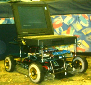
The aim of this project was to create a prototype MIRC to show how a PC based robot could be developed. The objective was to produce a basic model with four wheels, standard sensors and a web cam forming the centre around which an individual could create their own custom robot with extra USB devices.
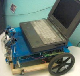
It was intended that the structure of the robot should be simple to facilitate easy adaptation and upgrading. The housing was designed to create three distinct layers within the MIRC to separate elements of the robot, thus leaving room to add more devices and a laptop computer when complete. The bottom layer would be designed for battery housing and mechanical hardware, such as wheels and sprockets, the middle layer to contain the main interface electronics, and the top layer to be for the external devices.
The MIRC was developed over a period of eight months. Initially research was conducted into robotic control systems, pc interfaces, sensors and actuators. A K8000 interface board formed the basis of the project, as it allowed for the connection of analogue sensors and actuators to the pc. The PC was chosen rather than built in micro processor because it was far more powerful and customisable.
 Sensors
The first type of sensors needed was proximity detectors. The sensors chosen for this were simple photo reflective IR devices. These sensors consist of an infra red LED and phototransistor in a plastic case; they would output a voltage that was dependant on the amount of IR light hitting the detector. Using analogue sensors enabled development of fuzzy logic to control how the robot avoided objects. These sensors worked well at short range as long as there was no ambient sunlight. It wasn’t until the weather got sunnier that it was realised how much the sunlight would affect operation. Sunshine affected the photo reflective sensors outputs by increasing output to about ¾ of maximum. Adding sunshine sensor and adjusting the other sensor values relative to it stopped the sunshine from making the outputs go too high but it reduced the range so much that they were useless.
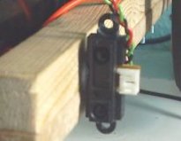
A much better type of sensor is the Sharp GPD-12 Infra red range finder. It is much larger in size than the photo reflective sensors but is much more accurate as it measures the angle of the reflected light as well as the intensity. On board signal processing then converts this to an analogue output voltage. The downside to this sensor is that it costs over £10. The GPD-12 is one in a range of infra red range finders by Sharp. They come with various output types and ranges.
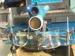 The head module on the MIRC contains several sensors, one of which is an ultrasonic range finder by Milford instruments [21]. This sensor uses the Polaroid transducer system, which has a single transducer for sending and receiving echoes. This is mounted on a servo for panning and is controlled by a board connected to the computers serial port. Another sensor in the head is a USB webcam of 640*480 pixels. Currently this has not been used in the project as the laptop being used does not support USB. With a more modern laptop this camera could be utilized for many functions, such as object recognition, motion tracking and remote avatar web conferencing.
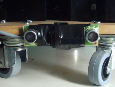 One sensor on the MIRC is an ultrasonic proximity detector. This is the Velleman K3502 parking radar kit. This kit usually sounds a buzzer when an object passes a preset distance from the sensor. To connect this sensor to the K8000 the buzzer was removed and the buzzer output was connected to a digital input on the K8000. There was no need to alter the voltage or the buzzer output, as the K8000 can tolerate a wide range of voltages (5-20V DC).
 Actuators
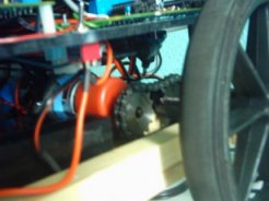
The main actuators of the MIRC are the two drive motors. Each motor drives one wheel independently. The original design involved using a four wheel drive system. Steering was done using he ‘tank drive’ method. This allows for a zero turning circle and therefore greater manoeuvrability in a small space. This method was found to be insufficient due to large amounts of slippage and torque requirements. The current method employs two large back drive wheels and castors at the front. The steering is done in the same way as the ‘tank drive’, but as the wheels are on the back the turning circle is increased to twice the length of the MIRC. The great reduction in slippage with this method meant that less torque was required and therefore better performance was achieved. The speed and direction of the motors can be controlled via the K8000 and H-Bridge driver board [22]. The motors are fitted with a 148:1 gear box to give greater torque, but this was still insufficient for the ‘tank drive’.
The other actuators are the pan and tilt servos for the head assembly. The panning servo is controlled by the same board that controls the Polaroid transducer range finder. The tilt servo is controlled by a separate board [21] which is capable of controlling up to 8 servos. This board is not currently connected due to the lack of ports on the laptop used in development.
 Robot Body (chasis)
The body of the MIRC consists of three layers. The bottom layer is for the drive mechanics and batteries, the middle layer is for the interface electronics and the top layer for the computer and room for expansion. The base was initially made from an aluminium sheet with aluminium shelving brackets along the sides for strength. This eventually had to be changed as the original base did not prove sturdy once the heavy batteries were added. Rapid acceleration and turning caused the whole base to flex, which eventually caused the chains between the motors and wheels to slip, and one of the gearboxes to break. This was one of the main obstacles that was overcome as it slowed progress and wasted funds. The new base is made from a piece of thick MDF with wooden supports for the bearings, and performs much more effectively.
The software currently being used to control the MIRC is written in QBASIC. This language is neither modern nor powerful, but it is relevant to the dated laptop used. At the beginning of the project it was difficult trying to get java programs to work adequately on the laptop. Finally it was realised that the laptops slow processor could not handle all the computation required by this platform independent code. Although QBASIC could not be used to produce an adequate final working program with a GUI, it was sufficient to control the majority of hardware. If a more modern computer had been available to work with better quality programs could have been produced and more advance hardware added. C++ was the preferred language but the editor and compiler were too complex for the laptop used. Editing on a PC and transferring compiled programs to the laptop was not practical due to it having faulty disk drives and communication ports.
 Fuzzy Logic Control Software
In order for a robot to function effectively in the home, it must be able to adapt to circumstances that the programmer may not have considered. If the program was not able to learn and adapt, the user would soon find that the robots abilities were quite limited. No matter how many situations and tasks it was programmed to deal with, there would always be something it would fail to ‘understand’. This is why software developed for the MIRC uses fuzzy algorithms.
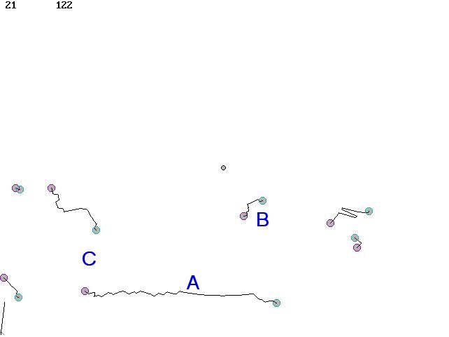
The current software does not involve fuzzy learning as this will take considerable time to develop, but example programs were created to demonstrate this. The first example does not involve learning but uses fuzzy logic to determine how the MIRC moves. This program (Appendix H) causes the MIRC to act like a finite state machine. [23] The program simply captures data from analogue range sensors on the front and sides of the MIRC. This data is then combined and converted to a value for the speed of each motor. If the MIRC approached an object that was on its left side, the right motor will slow down causing it to move away. The closer the MIRC is to the object the more the wheel will slow down, causing it to turn sharper. The outcome of this is that the MIRC behaves more like an animal than a machine. The QBASIC code for combining the sensor values and changing the motor speed is shown in figure 6 below.
|
LTemp = (64 – (2 * SQR((((RFront – RFrontC) / 3) * ((RFront – RFrontC) / 3)) + (((sen%(3) – senC%(3)) / 3) * ((sen%(3) – senC%(3)) / 3)))))
|
Figure 6. Changing speed of the motor, relative to all sensor readings
This is one line of code. LTemp is eventually used as the speed value for the left motor. The other variables are the sensor values. This applied to both motors, causes the effect mentioned previously and also will cause the MIRC to slow down if passing through a small space.
Another example program created was a fuzzy line follower (Appendix I). This program uses similar algorithms to the object avoider program. Two photo reflective sensors are mounted on the front of the MIRC for detecting lines. Different types and colours of lines were tried and the relevant programs created for them, but it was found that slow polling of the sensors would only allow for gently bending lines to be followed. If a faster computer was available, sensor data could be captured faster and therefore sharper bends could be followed.
To demonstrate fuzzy learning, a program was created that simulated evolution. (see A.I.) The program creates a type of predator and prey environment where one species hunts another for food. The prey are just simple circles which move around randomly on the computer screen. Each one has its own set of parameters which define how fast it moves and how erratically it behaves. The predators are the evolving species which eat the prey, move around and breed. Each one has its own unique set of variables which governs behaviour. This is their simulated DNA. When the program starts several prey are generated and one just predator. The ‘DNA’ for this initial predator is randomly generated. It is attracted to the prey so it chases them until it is close enough to eat. Once the predator has eaten enough food it will make a copy of its self but with some slight mutations in its ‘DNA’. The mutations may have positive or negative effects, such as being able to survive longer without food, or becoming less agile. At first the majority of predators will group together, but by the time several generations have lived and died, distinct groups can be seen. Using this method, a robot could be the predator, and the prey could be its charging station or tasks it meant to perform.
The resultant MIRC combined with a laptop appears in presentation as a robot. It has achieved its original objective of mobilisation of which can perform a range of simple tasks determined by the software used. Whilst the project has achieved its aims, there is limitless capacity to develop further to reach its full potential. With funding and further experimentation this humble foundation could prove a stepping stone to real functional usage of this type of technology. The production of an advanced MIRC is possible at a reasonable cost with mass production and as such could impact on everyday life.
Currently there is no main program or OS. Eventually it will be a mainly fuzzy controlled system. It appears rather pointless trying to create a precise, accurate system as it would cost large amounts of money and time to make it work. The intended outcome is to create a kind of fuzzy logic based cyber pet. This would mean that a MIRC based robot would act more like an animal than a sophisticated machine. Learning algorithms could enable you to teach it tricks just like you do with a dog, rewarding good behaviour and punishing it if it does something wrong.
Throughout this project a great deal of knowledge has been gained in various areas of cybernetics, and a significant project achievement has been reached. Images of the competed MIRC are available on the attached CD. The MIRC created for this project will continue to provide learning opportunities as it continues to develop and improve. A point to stress is how difficult turning theory into practice actually is. Testing very often showed unexpected results. A lot of time can be used getting things to work the way they were intended to, and very often a compromise is necessary.
There is much more work that can be carried out on this project: – Once the oddometry is working effectively, a charging station for the robot could be built to locate when in need of recharging. Armed with a modern laptop, the next step will be to incorporate the webcam and wireless networking. With image processing a robot could recognise objects, rooms or even faces. Another thing to add is a robot arm. There are already robot arms available for purchase that can plug into a USB port, although a custom design may prove more effective. Eventually the entire MIRC will be connectable to a laptop by one single USB cable as this would make connection simple. Also a USB hub could be built in to the MIRC for simple addition of hardware such as robot arms or a barcode reader.
The ability of modern computers to connect to wireless networks is an important factor to the potential success of the MIRC. Being connected to the internet not only gives the MIRC access to large amounts of data. It also means that it could be connected to other networks such as mobile telephone networks. This opens the doors for a whole new interactive system. A person wishing to make a MIRC based security robot could monitor it from anywhere. Data and images could be sent to a multimedia telephone or instructions sent back to it. The most popular use of this is expected to be web conferencing. A person could use the MIRC like a remote avatar, allowing them to ‘step inside’ it and drive it around.
Laptop controlled MIRCs could be networked together, enabling them to work as a team to complete the same objective. This could even be done with the robots in different parts of the world. Groups of robots could be simultaneously controlled by a single user. Using the fuzzy style of programming described earlier, several robots could share all their sensor data and process it between them. This could act like a shared ‘conciseness’ making each individual robot more like a single part of one machine, rather than individual robots communicating and working as a team.
This article is a short version taken from the main project report.
To see the full documentation for Project MIRC, click here.
THere is a new version of this project using moder electronics and software. See the DIY Robot II
 This is very simple device that uses a simple mechanism to animate some small puppets to make them look like they are dancing.
The mechanism converts the rotary motion of a motor into a linear motion that oscillates with simple harmonic motion (SHM). This means if the velocity of the rod was plotted on a graph, it would look like a typical sine wave. It is just a simple push-pull type device that is used to move a long rod back and forth. The moving rod will be used to transfer the motion to two puppets, side by side.
The images below show the mechanisms used to transfer motion to the puppets. The wooden ‘T’ piece tilts left to right repeatedly. It is linked to the main rod by a short length of silicon tubing which stretches ant the end of each stroke. The stretching of the tubing at the end of the stroke means that the motion of the puppets is more rhythmic because they stop briefly before changing direction. This helps to randomise the movements of the freely swinging arms and legs.
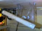
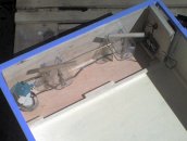 The mechanism is installed in a custom wooden box. The puppets are suspended from the ‘T’ piece by nylon strings attached to the hands and feet, and the main body is suspended from a fixed point to carry the weight.
To reduce the noise output from the device, the mechanism is boxed in with foam lined walls, and the joints are greased to reduce friction. The strings pass through small holes in the lower section so that the puppets are suspended in an independent cavity.
The speed of the motion is controlled using a simple pulse width modulator circuit based on a 555 timer IC. When powered by 6V DC the speed can be varied between stationary and ‘crazy’ where the puppets are moving very erratically. This allow the device to be used for longer periods because if the battery level falls the speed controller can be turned up to accommodate it.
These dancers are also able to demonstrate resonance! When the speed is adjusted just right, it is possible to ‘tune in’ to a part of the puppet which makes the movement suddenly become erratic and more significant.
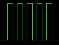 This page shows you how to make a super simple square wave signal generator. The circuit below uses a 555 timer chip, a capacitor, and some resistors to generate a variable frequency, variable pulse width square wave. The term ‘dead bug’ refers to the way that the finished circuit resembles a dead insect. This is because the solder connections are made directly to the components and there are legs sticking out making it look much more messy than the diagram below.
This is a very basic circuit and therefore does not produce an ideal square wave over the full frequency range. The pulse width or duty cycle can only be varied by a small amount, and doing so also effects the frequency output.
If you want to try a more advanced and more accurate version see the DIY Signal Generator II
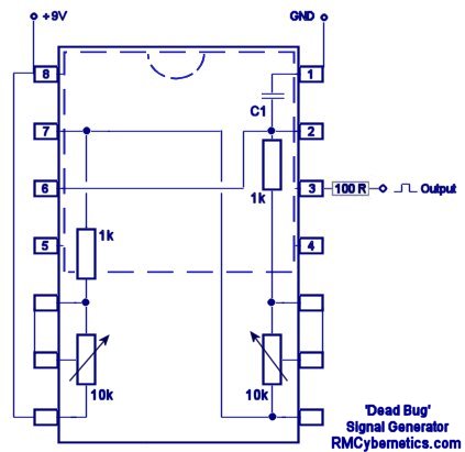
This diagram shows how the circuit can be wired without the need for any circuit board. A 14 pin IC socket is used to hold the main circuit so the 555 chip and the two pots can be simply plugged in. The total parts list is shown below.
14 pin IC Socket
NE555N Timer IC
1k Resistors x2
10k Variable Resistor/ Potentiometer x2
Capacitor selection for C1
If you want to switch loads like coils, motors and lights, our range of Cyber Circuits are for you!
The diagram represents a view from below and is not to scale. The circuit may be a little tricky to solder, but its about as simple as you can get for a signal generator.
This circuit can be used in the DIY Tesla Coil project as part of the Ignition Coil Driver
The value of the capacitor C1 will determine the range of frequencies produced. Somewhere around 0.1 to 0.01 microfarads should be adequate for mid range audio frequencies.
This circuit is very simple and has a fantastic range of potential uses. The two potentiometers (variable resistors) allow the frequency and pulse width to be varied independently and without affecting each other like in the super simple signal generator.
By incorporating a rotary switch, the value of the timing capacitor (C1) can be adjusted. This allows the frequency to be adjusted over the full range that the 555 timer can support.
A separate chip (LM393) is used to control the pulse width so that it will not effect the frequency. The LM393 is a ‘Low Power Low Offset Voltage Dual Comparator’ The pot (VR2) is used as part of a voltage divider so that the voltage on the inverting input of the comparator can be smoothly varied. This voltage determines the pulse width of the final output signal.
Like this circuit? Check out our range of Pulse width modulation circuits.
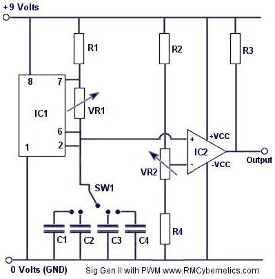
| IC1 | LM555 |
| IC2 | LM393 |
| R1 | 10k |
| R2 | 10k |
| R3 | 2.2k |
| R4 | 10k |
| VR1 | 1M |
| VR2 | 10k |
| C1 | 47nF |
| C2 | 4.7nF |
| C3 | 470pF |
| C4 | 47pF |
| SW1 | 4 Pole Rotary |
Since the pulse width is relative to the input voltage on the this input, it is possible to use the circuit in conjunction with a multitude of robotic interface boards. This signal can be used to drive a H-Bridge or power transistor which is ideal for varying the speed of a DC motor. We have some circuits based on this idea on the Cyber Circuits page. We also have a simple DIY version of this device here
Potential Uses Might Include:
DC Motor Speed Control Control
Boosting or Variable Dimming for LED’s and Light Bulbs
Transformer or Ignition Coil Driver
This circuit was used in the Power Pulse Generator project as part of the Ignition Coil Driver
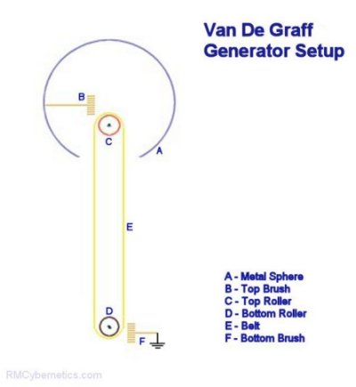
There are a number of devices that utilise contact electrification. A popular device is the Van De Graff Generator as it is very simple to construct. This device will produce very high voltage electricity at very low current. This means that they can be safe to touch, although it may make your hair stand on end!
It works by using two rollers and a belt made from dissimilar materials. As the belt rotates, charge separation will continually occur at the point where the belt moves away from each roller. If a metal brush is placed near to these points then the charge can be collected or deposited. The choice of belt and roller materials will determine the polarity of the voltage produced.
 A very simple mini Van De Graff Generator can be made from household parts. It wont make your hair stand on end, but it could produce as much as 20,000 Volts. The following parts (or equivalent) can be used for this project.
Large rubber band
Large glass fuse
Small metal rod, or a nail
Plastic pipe (~4cm diameter)
Insulation tape
Small motor & batteries
Empty drinks can
Wire
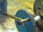
First of all a piece of PVC pipe or an equivalent insulating support is cut to size. To this the rollers are attached at each end. The top roller should just spin freely on its axle. The bottom roller should be parallel to the top one and raised up from the base of the support so that is can spin freely and be driven by a motor.
The belt should not be too tight that it creates excess friction as this would be noisy and inefficient. It is common to create a belt driven pulley to link the motor to your bottom roller as this provides a speed reduction and torque increase from the motor. A motor speed controller would also help so that the speed can be adjusted for optimum results.
The wire brushes should be place near to but not touching the roller or belt. It is likely that you will need to experimentally determine the optimum position of the brushes.
The top sphere acts like a capacitor to store energy in the form of displaced charges. Ideally is should be large, round and smooth. Any sharp protrusions on the outside of the sphere will cause corona leakage and prevent a good build up of charge. A single drinks can will work on a small scale and they can even be stacked together for better results.
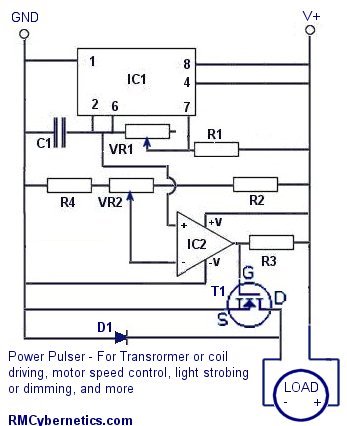
This device uses a built in pulse width modulated signal generator circuit for triggering a power MOSFET.
The circuit is great for controlling the power delivered to a device such as a fan, LED’s or even transformers and coils. By adjusting the pulse width you can easily control the speed of a fan without sacrificing torque.
The transistor used is not critical but generally something with voltage and current ratings suited to your application should be used. We have a range of MOSFETs and IGBTs available. The circuit will run from a 6V – 12V DC supply and the output can be made as ‘open collector’ for higher voltage switching.
Don’t fancy building this DIY PWM Circuit yourself? Check out our range of advanced pulse generators
This circuit diagram shows the load (coil, motor etc) connected to the same supply as the rest of the circuit for simplicity. If you need to switch a higher voltage, the +ve connector of the load can simply be connected to an external supply.
|
Parts List
|
|
| IC1 | LM555 |
| IC2 | LM393 |
| R1 | 10k |
| R2 | 10k |
| R3 | 2.2k |
| R4 | 10k |
| VR1 | 1M |
| VR2 | 10k |
| C1 | 47nF |
| T1 | IRF740 or simlar |
If the circuit is to be used with inductive loads a small capacitor should be connected across the load These are often already fitted on small DC motors. An additional component such as a varistor or ‘freewheel diode’ is also recommended if the pulse generator is driving high voltage flyback transformers like ignition coils.
The two potentiometers VR1 and VR2 are used for controlling the frequency and duty cycle of the output. VR1 adjusts the rate at which C1 is charged for modifying frequency, while VR2 acts as a potential divider allowing a specific voltage to be put on the inverting input of IC2. This voltage is used to control the pulse width of the output. The output duty cycle or pulse width of the device can also be controlled by an external voltage such as a microcontrollers or analog signal. The analog voltage source can simply be connected to the inverting input instead of the output from VR2.
We have a few of these pulse generators designed for use with high voltage transformers which available on the cyber circuits page. These are high quality, ready made on a PCB including a large heatsink and fan, overload protection, and back e.m.f. inductive protection. Theses devices are quite resilient and are ideal for hobbyists and experimenting due to the wide range of potential uses and durability for handling varied loads. If you have random transformers or are making your own coils, these power pulse modulators are ideal for testing and driving them.
Don’t fancy building it yourself? Check out our advanced pulse control circuits. Buy our awesome PWM-OCXI now!
 Using a voltage multiplier is a great way to make a high voltage DC power supply. It is very easy to generate high voltages from easily available components.
This page contains information on where to buy the components and how to connect them. It also gives details of sources of mini high voltage power supplys (inverters) which will run from batteries.
![]() WARNING: Very High Voltage Device!
WARNING: Very High Voltage Device!
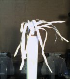
 You can see what high voltage static electricity from this device does to a piece of one way window film in the violent discharge experiments section. There are microscope images of the aftermath and a video clip of the explosive action!
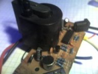
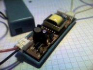
For efficiency a voltage multiplier should be powered from a source that is already a relatively high voltage. There are a variety of small battery operated high voltage power supplys available. Many lighting devices contain inverters for powering vacuum tubes such as, florescent lights, cold cathode lights and plasma globes. These types of devices usually run from 12V DC and can output voltages up to around 20kV AC.
|
Mini cold cathode tube PSU – ~1kV |
Plasma Globe PSU – ~15kV |
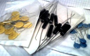 The capacitors and diodes required for the multiplier can be purchased from our shop.
The capacitors and diodes can be arranged in a variety of ways. The half wave method is the easiest as it requires fewer components, but a full wave circuit will perform better. If you just want to get one working as soon as possible the the half wave method would be adequate. The circuit diagrams below indicate how the components should be arranged.
|
Component
|
Max Voltage
|
Source
|
|
1 – 30kV
|
||
|
1 – 30kV
|
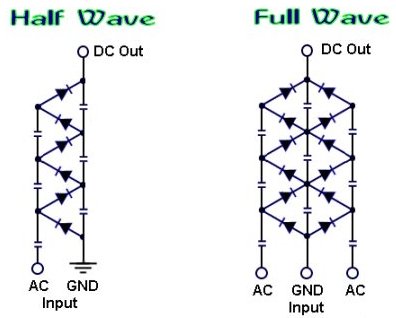
 The schematics above will output a positive DC voltage relative to the ground (GND). If a negative output is required then the polarity of the diodes should be reversed. you can learn more about how a voltage multiplier works, by visiting the voltage multiplier page.
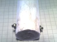
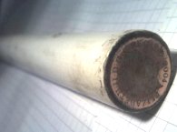
For safety and improved performance the voltage multiplier should be placed in a protective casing, such as a PVC pipe filled with oil. The image on the left shows two protruding screws used for the AC input connection, and he other image shows polished coin used for the high voltage output. By using Polymorph to seal the ends of the pipe, it can be filled with oil to prevent corona leakage from the internal connections. A more sturdy method would be to fill the pipe with epoxy resin, but this may be difficult with compact component arrangement.
 Example Experiments
A homemade voltage multiplier is perfect for powering an EHD thruster (aka Lifter). An EHDT can be made from just aluminium foil, sticks, and fine wire. To learn how , see the ElectroHydroDynamic Thruster page.
Using freezer spray (used by plumbers) you can grow ice crystals on the HV output with interesting results.
For more Simple Experiments with static electricity see the Experiments Section
 Induction Heater Circuit - CRO-SM3
Price range: $159.89 through $177.21
Induction Heater Circuit - CRO-SM3
Price range: $159.89 through $177.21
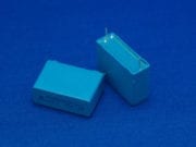 Polypropylene Capacitor 400V 330nF
$3.32
Power Pulse Modulator - PWM-OCXi v3
$145.88
Polypropylene Capacitor 400V 330nF
$3.32
Power Pulse Modulator - PWM-OCXi v3
$145.88
 Power Pulse Modulator - PWM-OCX v3
$128.91
Power Pulse Modulator - PWM-OCX v3
$128.91
 Solid State Relay 40A
$17.31
Solid State Relay 40A
$17.31