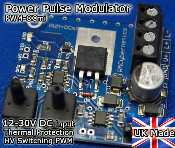
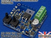
Power Pulse Modulator – PWM-OCmi (HV)
Miniature PWM Circuit for use with high voltages
up to 300V, 3.5A
$53.59
11 in stock (can be backordered)
Description
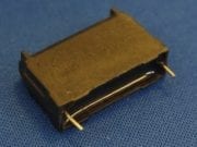
The PWM-OCmi is an ultra miniature power pulse width modulation control circuit. Despite its tiny size the PWM-OCmi is capable of controlling a large amount of power which makes it great for embedding in your projects without taking up space. The PCB can also be screwed to a suitable heatsink to improve the device’s power handling capabilities.
The OCmi is primarily designed for use in high voltage projects such as Ignition coil driving, flyback control, magnetic resonance experiments, or any other application which would generate significant transient voltages. For low voltage projects, we recommend the OCm as this is more efficient at low voltages. You can switch mains powered devices by adding a Solid State Relay to the output. When driving ignition coils, don’t forget to keep the duty setting low to prevent overloading the circuit. For high power output use the PWM-OCXi v3.
Features
It has a range of onboard components for dealing with transients and voltage spikes caused by noisy loads like ignition coils. This allows the device to run with high performance levels even when in a demanding environment. Also included is a built in thermal shutdown feature which will disable the PWM output if the switching transistor is too hot. The output is automatically restarted once it has cooled again.
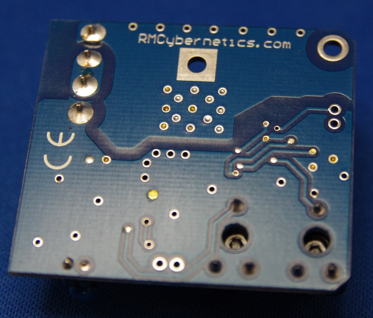
The PCB contains four connector pads at the perimeter which allow the device to be enabled, or interrupted from another signal source, or even another Power Pulse Modulator. They also allow for monitoring the onboard oscillator, or modulation of its frequency.
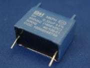
The compact design is built in the UK on a high quality dual layer PCB with 2oz copper (twice as much as standard circuits) for durability and performance. This high quality, low cost PWM-OCmi is ideal for embedding in your projects due to its small size and adjustability. The onboard timing capacitor is fitted in a socket on the PCB so that it can easily be changed for producing other frequency ranges.
Please note: Printed manuals are not supplied. Please download or print the manual using the link below.
Specifications:
| Input Voltage(DC) | 12 – 30V |
|---|---|
| Max Switching Voltage | 300V |
| Max continuous Current | 3.5A |
| Frequency | 0 – 100kHz(requires fitting of capacitors for full frequency range) |
| Duty Cycle | 0 – 100% |
| Footprint(mm) | 45 x 50 |
Thermal Overload Protected
Need a different spec? Customisation available from £25 or check our other Pulse Generators
Example Applications
• Ignition Coil Driver, Fuel Injector Control
• Flyback Transformer Driver
• DC-DC converters, inverters, and SMPS
• Solenoid Pulser
• LED or Light Bulb Dimming and Strobing
• Electrolysis and Electroplating
• Motor Speed Control
• Resonant Energy or Magnetic Pulse Experiments
• And more…
For full details and specifications – Download the PWM-OCmi Instruction Manual
Related Videos (links open in new window)
Plasma Gun, Plasma Gun 2, Arcing, Jacobs Ladder
Product Tutorials
Driving inductive loads, Making a Jacobs Ladder, More
| Weight | 0.1 kg |
|---|---|
| Dimensions | 5.10000000 × 4.50000000 × 2.00000000 mm |
Only logged in customers who have purchased this product may leave a review.
Related products


 Price range: $130.64 through $198.99
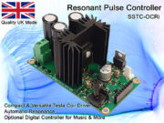
Resonant Pulse Controller – SSTC-OCRi
 Price range: $2.00 through $9.90
High Voltage Diodes
 Price range: $113.89 through $239.86
Kirlian Photo Plate
 Price range: $52.25 through $60.96


Benjamin Weimer (verified owner) –
I liked this product a lot. Hooked it up in a simple circuit and worked great with a regular lawn mower spark plug and ignition coil.
Despite adding a timing capacitor and the system having thermal protection, as it says in description, I had a burn through on the switching transistor when I cranked up the frequency (probably way too much). It didn’t shut down automatically like it says it should, so I’d be curious to know why that happened.
Regardless, I’ll be buying another because I need it for my project and can compensate with adding a heat sink setup and being careful with the frequency I set it too! Great quality little board and comes ready to go. Definitely recommended.
RMCybernetics –
Hi Benjamin,
Thanks for your feedback. When running at high frequency or curent, the internal part of the transistor can heat up significantly faster than the outer part where the sensor is. If running the system hot, it is important to only make small changes to operatng parameters for there to be enough time for heat to move through.
garry –
seriously cool! big sparks, tiny circuit!