Driving Inductive Loads
Driving inductive loads
When driving electromagnetic devices with square pulses, there are a range of effects that can cause problems. At certain frequencies most inductive loads will produce significant voltage transients which can damage the driving circuit, or cause the circuit battery and controls to float at a dangerously high voltage.
At low power levels the PWM-OCmi will deal with the transients at any frequency, but at higher power levels, extra circuitry may be required. If you turn up the duty setting too high when driving an ignition coil for example, the transistor or other components will rapidly overheat. If you need something more versatile then you should use the PWM-OCXi (v2) as this has advanced protection and automatically prevents the voltage spikes getting too large and causing overheating.
What causes transient voltage spikes?
When a current is flowing in a coil, there is a magnetic field around it which is storing energy. When this current is interrupted (at the end of each pulse), this magnetic field collapses and the energy within it must go somewhere.
The collapsing field will induce a current flow (in the opposite direction to the original one) in the coil which then also creates a magnetic field. This will happen very quickly and the result is a very fast (high frequency) oscillation in the coil.
When the transistor switches off and the field begins to collapse, the open circuit means that the current can’t easily flow around the coil because of the large impedance of the transistor in the off state. This large impedance means that the current flow must be very small (see ohm s law), but because of energy in the field, the voltage will become very large.
Using A Fast Diode
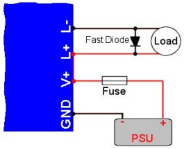 Simply placing a fast diode between your load connections will significantly reduce transients. This is the most effective way, but in some circumstances the diode may prevent proper operation. When driving ignition coils, the diode will prevent it from producing a high voltage output because they work by deliberately making a voltage spike. See the other methods for protecting your circuit when driving ignition coils.
The diode simply serves as a path for the current to flow when the magnetic field initially collapses at the end of the pulse. It is often called a ‘freewheel diode’ as it allows the current to free wheel around the coil. Since the reverse current now has a low impedance path, this current will be high, and the voltage will be low.
One important thing to note is that high current creates more heat and the diode will therefore need to be able to tolerate this and may need to be mounted on a heatsink.
The reason a fast diode is suggested is so that it will begin conducting as early as possible to prevent the voltage from rising too high.
We suggest using an STPS1545D schottky diode for low voltage circuits, or a BYV34 diode and have them mounted on a suitable heatsink.
Using a MOV / TVS
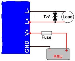 Using either a TVS (Transient Voltage Suppressor), pair of zener diodes, or a MOV (Metal Oxide Varistor) is a way to reduce high voltage spikes, yet with less free wheel currents that you may get from using a diode as described above. These are already built into our circuits, but it can help to add additional ones near your load device.
These devices are normally non-conductive and will have no effect on the circuit. Only when the voltage between their terminals exceeds their rated value will they begin conducting. When this happens they will ‘short out’ the voltage spikes and provide a free wheel current path until the voltage drops again.
The advantage of this is that they automatically activate in the presence of high voltages, and then deactivate when the voltage is low again. This means that the current is not always free wheeling as it would with a diode and is therefore useful with ignition coils. These components however will soon heat up if the voltage spikes are too frequent and they are not available for very high power levels.
We suggest using a 1.5KE440CA (for OCXI) or 1.5KE56CA (for OCX).
Using a Snubber
 A snubber reduces transients by slowing the rate of change of voltage (dV/dt)between the load terminals.
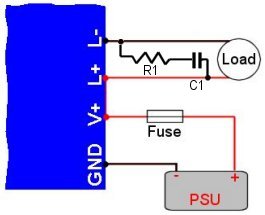
By placing a resistor and capacitor in series between the load terminals, the capacitor acts as a sort of buffer that must be charged before the voltage can rise. The resistor serves to limit the current so that performance of the circuit is not significantly reduced. The snubber will dissipate power as heat, so you should therefore use a large power resistor and a quality capacitor that is suitable for pulsed applications.
Due to the combination of capacitance and inductance, there will be certain resonant modes that may or may not be useful to your application. This means that the snubber will have a different effectiveness at different frequencies. You need to choose the value for R1 and C1 to suit the frequencies you want to work with.
We suggest using a 330nF 1kV capacitor, and a 100 ohm 50W resistor for general use.
Working with high voltages
 These circuits can be used with, or to generate dangerous high voltage electricity. Proper safety precautions should be made to avoid accidents or injury. A few basic safety notes are outlined here, but you should make sure you determine and implement any other safety measures that may be necessary for your project.
When using high voltages (above 30V), you should earth the metal control pots and/or insulate them with a suitable cover. This can be done with a wire connecting the pot body to a nearby ground point on the PCB, or by enclosing the unit in an earthed metal box. The GND terminal of the PCB should then also be connected to a suitable earth point.