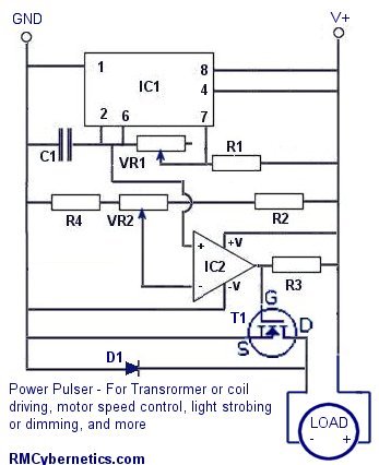
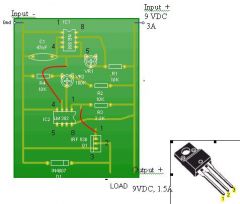
A DIY Power Pulse Controller
This device uses a built in pulse width modulated signal generator circuit for triggering a power MOSFET.
The circuit is great for controlling the power delivered to a device such as a fan, LED’s or even transformers and coils. By adjusting the pulse width you can easily control the speed of a fan without sacrificing torque.
The transistor used is not critical but generally something with voltage and current ratings suited to your application should be used. We have a range of MOSFETs and IGBTs available. The circuit will run from a 6V – 12V DC supply and the output can be made as ‘open collector’ for higher voltage switching.
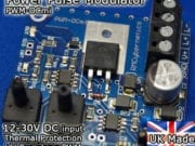
Don’t fancy building this DIY PWM Circuit yourself? Check out our range of advanced pulse generators
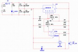
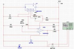
This circuit diagram shows the load (coil, motor etc) connected to the same supply as the rest of the circuit for simplicity. If you need to switch a higher voltage, the +ve connector of the load can simply be connected to an external supply.
|
Parts List
|
|
| IC1 | LM555 |
| IC2 | LM393 |
| R1 | 10k |
| R2 | 10k |
| R3 | 2.2k |
| R4 | 10k |
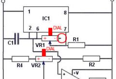
| VR1 | 1M |
| VR2 | 10k |
| C1 | 47nF |
| T1 | IRF740 or simlar |
If the circuit is to be used with inductive loads a small capacitor should be connected across the load These are often already fitted on small DC motors. An additional component such as a varistor or ‘freewheel diode’ is also recommended if the pulse generator is driving high voltage flyback transformers like ignition coils.
The two potentiometers VR1 and VR2 are used for controlling the frequency and duty cycle of the output. VR1 adjusts the rate at which C1 is charged for modifying frequency, while VR2 acts as a potential divider allowing a specific voltage to be put on the inverting input of IC2. This voltage is used to control the pulse width of the output. The output duty cycle or pulse width of the device can also be controlled by an external voltage such as a microcontrollers or analog signal. The analog voltage source can simply be connected to the inverting input instead of the output from VR2.


Features and Specifications
- Input 9 to 15V, 10A
- Power Output – 9 to 15V DC Square wave
- Open collector output allows for use of separate voltage source for pulses.
- Independent frequency and pulse width / duty cycle controls
- Frequency adjustable between 0Hz and 125kHz (C1 must be changed for full range)
- Pulse width fully adjustable between 0% and 100%
We have a few of these pulse generators designed for use with high voltage transformers which available on the cyber circuits page. These are high quality, ready made on a PCB including a large heatsink and fan, overload protection, and back e.m.f. inductive protection. Theses devices are quite resilient and are ideal for hobbyists and experimenting due to the wide range of potential uses and durability for handling varied loads. If you have random transformers or are making your own coils, these power pulse modulators are ideal for testing and driving them.
Don’t fancy building it yourself? Check out our advanced pulse control circuits. Buy our awesome PWM-OCXI now!


Hello 🙂
I am a novice and can’t figure out what pins to use on IC2 (LM393)
Please help
TIA
Inputs +/- are Pins 3/2. Output is pin 1
V+ is Pin 8, and GND is pin 4
would this circuit work with a PNP transistor? i tried using a tip31a NPN which worked great for low side switching but when i tried high side the wave form on the scope is rounded on the switch off. the reason i want high side switching is because i want to have the emitter of the tip31a and ground go into an RCA cable which will then operate the main transistor bank from several feet away. the tip31a was going to make up an amplifier stage with an lm317 variable voltage regulator so i can control the power throughput (experimental idea) on the scope this idea works for low side switching, however high side also gave the problem of increasing the amplitude of both square wave signals as opposed to just the intended voltage increase at the output of the tip31a. after some google searching it is leading me down the PNP route although this may not be the solution problem..
to clear things up, I believe the topology I am referring to is emitter follower. base will be the input from the signal generator and the emitter will be amplified signal out.
PNP drive requirement is a bit different so you would need to adapt the circuit accordingly. See this page for info.
http://www.w9xt.com/page_microdesign_pt12_hv_pnp_switching.html
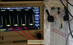
there is ringing on the edges too…the particular burst moves with the frequency, it ends up moving towards the edge and at some point it merges with the edge…fet was not even connected…
this was checked on 2 scopes…
Usually the ringing appears at the edge of the trasition. In you photo it looks like it is showing up in the middle of the low part of the pulse. Perhaps your scope is not displaying it right. Reducing ringing can get fairly complicated so have a look around the internet for examples. This article on ringing reduction techniques might help.
my nephew make a circuit on the breadboard (see image) and it has hifreq. ringing on lower end of the square, even on pretty low frequencies. i’m guessing it’s parasitic cap. and inductances of those long wires, but would that appear on rather low frequencies? what portion of the circuit is most sensitive to these influences? you mention decoupling caps above, between +12v rail and the ground?
If you mean meters for frequency and duty, then you would need some sort of frequency counter, or make one using something like our PDI-1. This if you mean voltage and current meter.
Can I add a couple of digital readouts and if so how do I do it?
If the frequency is set low enough, the solenoid will stoke on each pulse and you can therefore contol the stroke timing. To control the stroke power, you need to set to a higher frequency so that adjusting the duty will adjust the average power proportionally.
Hi
I am a complete novice when it comes to electronics but I am willing to have a go!
The question is will this unit control the stroke timing and also the power of the stroke eg: the amount of force generated?
Make sure you have a pullup resistor on the output pin. The 393 does not source any current on the output, it only pulls to GND or floats.
I love your website and products. I haven’t gotten the comparator to work and its driving me nuts. I’ve got a LM393p. Pin 3 has a 5v sawtooth to it. Pin 2 is 3-7 volt dc to it. Pin4 grnd pin 8 +12v. And no output on pin 1. Any ideas?
Jed, Check this page on 555 timer calculations
Evan, The heat in the FET will be due to the current flowing through it. If you want to pass a lot of current then you ned to cool it very well, and/or choose a FET with a low Rds(on) value.
I cannot tell you enough how much I appreciate you providing this circuit. Thank you!
This is my third attempt at this DIY board and I am about to pull my hair out! Can you please help me identify what it is that I am doing wrong? The very first board I made turned out to work on the first try but then the FET over heated and melted my breadboard. A massive heat sink was connected with heat sink compound and a heat transfer pad too. Thank you for your time and help!
I want the frequency to have a max range of 60 Hz, what rating of C1 must be used? or do you have a formula to solved the value of C1, can you share it.
No, for a bipolar output you would need a H-Bridge circuit. Maybe somthing like our induction heater project would help.
To modify this for a bipolar output (e.g., to power a pair of alternating or "wig-wag" lights) would it be possible to tie T1(G) to an inverting op amp leading to G of another MOSFET, T2? If so, would current sink limits of the LM393 require its output to be amplified before feeding the two G’s? [Thanks in advance.]
When you drive a coil there is a lot of electrical noise generated. When the arc breaks, all that energy that would otherwise be dissipated in the spark is reflected back to your circuit at high voltage. This can destroy components trough over voltage conditions and it can make things not work well due to making the voltage levels all over the circuit fluctuate significantly. Our OCXi v2 PWM Circuits have a lot of extra circuitry built in to deal with this.
Hi
When extending the spark gap until its too large to spark, the LM393 cooks but the NE555 remains cool as well as the main mosfet.
Whats causing the LM393 to get hot?
Thanks 🙂
G
Either the MOSFET is faulty or you are connecting it wrong. The MOSFET gate pin is only capacitively coupled to the rest of the circuit and would not cause the effects you describe unless faulty.
Thank you for what you answered,, but it doesn’t get to the problem. When there is no load connected; and there is no MOSFET in the circuit, the 555 and 393 operate beautifully.
When the MOSFET is connected, that is when the output signals from the 393 only reach 3 volts — something is holding it down to the 3 volts I spoke of with the changed waveform; and also the MOSFET is not switching on and off.
Why would just inserting a MOSFET to it’s base, with no load connected; "tank" the circuitry so that it doesn’t work at all? Any more ideas other than adding a MOSFET driver to the circuit?
Thanks again,
Scott
If the voltage is dropping when you add a load, it could be due to the PSU not being able to deal with the current demand. Add a 12V regulator and smoothing capacitors to the supply for the control electronics to help smooth out any surges.
The comparator in this circuit will only switch off the MOSFET when the signal is low. When high, the comparator output is floating, thus the gate is charged via the resistor R3. While reducing the value of R3 will increase the speed at which the transistor switches on, it must not be so low that it will cause the comparator to sink more than its rated current.
You may also want to add 220nF decoupling capacitors as close as possible to the V+ pins of the ICs. This also helps prevent noise from interfering with smooth operation of the circuit.
Hi Richard (again),
That’s what happens when one has to go into the hopital to have a very necessary neck operation to save what right hand operation I still have — I hit a wrong key. I apologize for the unfinished entry.
What I was saying is that the circuitry works beautifully when there is no MOSFET in the circuit (no load. But as soon as one is introduced, the gate signal goes from 11+V (V+ in this case) to about 3 volts and the signal widens to what is at least 25% duty cycle when it was just a trace width. AS the pull-up, 10 turn, 10 kohm pot is adjusted to increase the gate voltage, the width of the duty cycle increases also. The low voltage signal looks like a small 30/60 triagle.
Any help you can give me will be greatly appreciated as I don’t want to put a driver in when you have said that the comparator should drive the MOSFET.
Thanks, Scott
Oops! I made the wrong Pulse Width Modulator (without MOSFET). I’ll add Mosfet IRF740 & Diode 1N4007, and remove the 4-pole switch and extra capacitors. Once again, reminding you I don’t have an oscilloscope, how do I tune the DIY induction heater using this Power Pulse COntroller? I am sorry, if my post doesn’t conforms your rules….you may reply me at abuhafss@yahoo.com
Use a diode across your load. A 1uF capacitor should do it for the low frequency
also is there any capacitance value for C1 that will give me an operable range of around 1-10 Hz or will i have to us emore than 1 capacitor? thank you.
if i use a power supply with 12 V and 4 A (i think my coil only pulls 1 A) what capacitor should i connect across the load and what varistor should i use. i am trying to control an ordinary electromagnetic coil in low frequency pulses? can you help?
Try connecting pin 4 of the 555 to the 12V supply. Some 555’s do not like this pin to be left floating as it is in this diagram.
Hello,
I have read all comments many times and have experimented with the circuit for days (just learning) and, it need some help… I have posted the image of the same circuit – I can not get the square wave… What am I doing wrong? Same on the breadboard lights up the musfet.
Thank You
I am wanting to control a vacuum relay with 0-5v TTL signal from 0-10 hertz. What do I need to change in circuit to achieve this?
Please see post 1754 on the ignition coil driver page for a basic example. Alternately you could have the BFY51 (or equivalent) with its collector connected to the gate of the IGBT, and its emitter grounded.
You should have a variable resistor in series with the transistor base terminal so that you can adjust how hard it switches.
Hello RMC! I have already bought an OC-10A PWM driver from you in the past and works like a charm. So now, it’s time to make something more powerful. I need a circuit to switch 12VDC (max 500-600 for bemf voltage but doesn’t matter too much)at 10 Amps. But the special part I also need is an audio frequency spectrum carrier to modulate audio as well. I mean variable amplitude modulated audio frequencies with a carrier of 10 – 20khz. With your circuit in this page I think I have 2 out of 3. 12VDC, variable frequency and cycle duty. Now could you please tell me how I could feed and amplitude modulate audio frequencies with this circuit? And with your circuit, I mean the MOSFET one, not the others with transistors.
Thank you very much in advance!
Check the Ignition coil driver page.
im geting high voltage spikes in the – input of the ignition coil where do put a varistor ?
a ignition coil, but it fry’s up when i connect the 12v, and i can’t get the load to turn on
It should work fine from 12V. What are you using for the load?
I built this circuit and it works fine on 9v but the lm393 burns out if I connect a 12v 7ah battery what do I do
Richard,
Thank you for your time.
Richard
No. 105V / 8264 ohms = 12.7 mA
The capacitor in the tank circuit needs to be charged so the initial peak current will be very high. I’m not going to continue this discussion here as it is not relevant to the article. As I have suggested before; if you need help with your project, you can hire us for project consultancy.
Hi Richard,
Thanks for the response. Both the high voltage booster board and the parallel current boosting circuit that I am trying to make work to supply additional current to the load (parallel to the high voltage board) both are supplied directly from the step-down 120 / 12 volt – 1000 mA wal wart I have been using all along. I have tested it and it’s capable of producing it’s rated output very cleanly. I have been using it in order to develop a system that is not too “high strung” and so far so good.
Again, the tank circuit has a much higher measured resonant “ohnic value” which should manifest itself in a very small amount of current flow. In fact, thoretically, using the 8264 mathmatically generated ohms of resistance from the tank, it would only require 0.0127057 mA of operating resonant current at 105 vdc. But that would make the operating 40+ mA output of the high voltage boost board sufficient to operate the tank — but that isn’t working. What has been your experince in getting high Q tank circuits to start to resonate? There really isn’t any written information available. Specifically do they required a lot of initial amperage and if so why.
Thanks in advance,
Richard
What is supplying the power to your regulator circuit? I suspect it has too much impedance.
Hi Richard,
I almost totally agree. Where there is a difference is in the Zt factor of the load — it’s a little over 8.2 kohms, as measured by my LRC meter and then computed using the formula Zt = Q x Xl (Q = 4573.1) and (Xl = 1.807+). The current figure was taken from an in line input monitoring package as used in RC Controlled Models; very quick and very accurate. WHat I have been trying to accomplish is to use a “current boost” circuit from the web that is basically used for adding current to the LM78XX range of voltage regulators, and using the BUV27 transistor which has plenty of “voltage” head room and current passing capability. I figure that the high voltage “boost” board that I am successfully using should react the same as the regulator except that the voltage increase/decrease levels are reversed. I am also using the 1 ohm and 10 ohm resistors as directed on the current boost web page. The initial additional circuitry increased the total current output capability of the setup by 100 mA to about 150mA. Instead of adding sets of resistors and additional BUV27s in parallel to the first addition as shown on other web pages for additional current boosting, I elected to parallel two more sets of resistors to the original, which reduced the total resistive value of each original resistor to 1/3 of it’s original value. This should have drastically increased the current thru-put but it only increased to a total of around 250 mA — which doesn’t seem to be enough to turn on the tank circuit at it’s required voltage level of 105 vdc.
Do you have any information as to why the additional current wasn’t produced, thus turning on the tank. On another webpage showing basically the same additions, if the resistive levels were reduced to 1/10 of their original value; the current level being added would be in the neighborhood of 5 Amps. I figured that being within 30% of that should have caused the circuitry to supply at least 1 – 2 Amps of boosted current.
Can you see anything that I am missing?
Also, is there something about using a resonant tank circuit, that is totally unconnected to any output circuitry, that would cause it to require such a large increase in current between the two voltage levels, 12 vdc and 105 vdc? Any information would be greatly appreciated and your the only person I know of that has any experience with resonant tank circuits. Thank you in advance for anything you can tell me.
Richard.
You need to calculate or measure your load impedance. Based on your figures, you can do the following calulations…
Z = 12V / 0.18A = 66.67 ohms
If you then work out the current that would flow when the voltage is increased to 105V….
I = 105V / 66.7 ohms = 1.57A
You can see that your PSUs 250mA rating falls well short of this and is therfore unsuitable.
These calculatons are based on Ohms Law.
Hi Richard,
Thanks for the response. I’m wired up as depicted here. I have also arrived at the same conclusion about the second PSU that you did, that it is not supplying enough current. The problem that I have is that I do not know of a way to ascertain what the required amperage level should be because the system will operate beautifully running on the output of of first PSU, which only required between 160 and 180 mA total from the source for the whole system at 12 vdc. Do you have any leads that I might use. The second PSU’s voltage output level is 105 vdc and has 250 mA capability when measured by a good VOM. Any help would be appreciated.
Richard L.
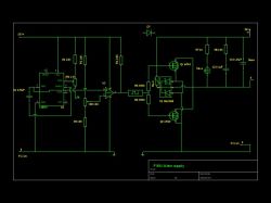
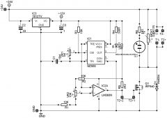
This diagram shows how it should be connected with a secondary supply. The V+ at the top supplys the circuit with power, while the V+ (secondary) supplys the load with power. There are two seperate PSUs such as batteries for example.
If your voltage is dropping, this indicates that your PSU is unable to supply enough current, or that you have something miswired.
Yes you can use a resonant load, but be aware of resonant voltage rise that may damage or interfere with the circuit.
Hello Richard,
Thank you for your response to my question that you graciously sent back. I’ll continue here as directed by that response.
Now that I understand that the second PSU pictured with your newer two PSU
controller module is another external PSU with a common ground to the first PSU, can that second PSU also be configured as a high voltage booster added adjacent to the PWM schematic pictured on this page? That would fulfil the common ground requirement and would supply a common 12 vdc input V+ for the two sections; which shouldn’t cause a problem — or would it?.
Secondly, previously I have tried to connect the output of a boosted high voltage section directly to my load as directed in your first response, but in the past; as soon as the direct high voltage connection is made; the high voltage level voltage drops to zero and the 12 vdc source input voltage level drops by at least 50 percent to around 5.5 vdc. Could it be that
the “open collector / open drain” condition for the ground switching MOSFET needs to be filfilled with a resistor with a value to be determined between the drain of the MOSFET and the boosted high level voltage V+ point in lieu of a direct connection? This would fill that particular “open collector / open drain” requirement as stated at the top of this page as being necessary for connecting a higher value voltage level to the load of the DIY Power Pulse Controller. This would also, in effect, make it a second pull up resistor, but the first one is used in the schematic for pulling up the gate drive voltage high enough to operate the MOSFET efficiently and the two shouldn’t cause a problem — or will it?.
Finally, I ask the following question because of your demonstrated knowledge base pertaining to Tesla based technology and resonance. Is there any reason that you are aware of that would preclude the use of a PWM schematic as pictured on this page with additional circuitry powering a high Q resonant tank circuit as the load if a boosted high voltage level output section was made available for connection to it?
I want to thank you for your helpo over the time that we have corresponded. It has been a great help.
Scott
I suspect your motor may be too large for it.
Hi RM
Thank you for your responses to my inquiry & your patience I will attempt to upload my circuit for a motor speed control power supply unit to drive a dc motor for building a coil winding machine, I have tried the suggestions you gave me but I guess I got something wrong because the motor did not turn it hummed for a short time then it blew the 7.5A fuse in my 36V power supply
The circuit is the first one I built it works fine for driving my ignition coils for my HV supply but not well for driving a motor
The capacitor should be about 1nf.
If you want something reliable, use one of our Power Pulse Modulators. The PWM-OCB would work great for pulsing fuel injectors.
i have built simple pulse controler it will dim a 12volt 21w bulb but not a 12volt 5w bulb. i want to use the controler for testing petrol injectors, i have tested it with an injector it just seems to click rather than pulse. i have used a 47nf capacitor in C1. you mentioned that a small capactor should be put accross load with induction coils, but what value should i use. could i run 4 injectors in paralell for testing or would that be to much for the controler. the injectors are about 14 ohms each.
Practical or not, that is the way you should do it. If you just rely on a single component to protect all your diodes, its failure would destroy every one of them.
Laser diodes typically use a constant current regulator, but again, you should use one of these per diode. Taking short cuts will just lead to poor results in the end.
Hi RM I need to use this circuit with many loads (lasers not LED’s) so adding a resistor for each load is just not practical – any suggestions would be appreciated.
A voltage regulator is used to keep a constant voltage, but this really is not the best approach.
You should make sure each individual LED has its own resistor that will limit current to within the LED’s specifications. This way whatever number of LED’s are connected, each one will get the right current.
Thanks heaps for your response RM.
I will use your suggestions for my testing.
I actually plan to connect this circuit to multiple diode array loads with current draw varing from 0.8A up to 8A – Is there a way that I can keep the output voltage constant at 3.5V under these various loads without having to change resistors?
You should put the resistor between the LED and the power supply.
You don’t calculate the resistor like that. If your LED is rated for 800mA max and you want to use a 6V supply, then you use ohms law as follows;
R = V / I
= 6 / 0.8
= 7.5 ohms
The resistor must also be rated for enough power;
P = I2R
= 0.82 x 7.5
= 4.8 watts
Hi I want to use this circuit to drive a bunch of diodes – load would be 3.5v 0.8A. In previous posts you have made a few suggestions namely:
1. Change the mosfet to a TIP142 transistor
2. Drop the extra volts across a resistor
I have built the circuit with a TIP142 and it worked well at 6V driving a light bulb – now if I want to drop the extra volts where would I connect the resistor? From collector (drain) to ground?
Given that I want to drop 2.5v and current is 800mA does that mean I need a 3ohm resistor? Seems low.
Yes. The best thing is to supply your IC’s via a voltage regulator and also include a fast diode reverse biased across the supply.
if i use a seperate power supply for my load(ignition coil) and tie the grounds together i know i can still damage the fet, but do i still have to worry about burning up ICs like several other have?
Dave,
Yes, tie the reset pin high. Not sure why you cant get lower than 45% though.
A MOSFET is a transistor. Do you mean a different type of transistor such as a bipolar type? The heat generated in your transistor depends on its parameters such as the ‘on state’ resistance and the switching speed.
hanyss,
No, you are not understanding how this circuit is working. The 555 is the oscillator. The comparator compares the voltage from C1 and VR2 to give a square wave output for driving the MOSFET.
thanks rmc..but now i was wondering what generate the pulse so can be injected to the gate mosfet?? it is generated by LM555?? and why this circuit just use only one comparator?? usually, to generate the pulse for mosfet it must have a several comparator to generate the pulse right?? or am i wrong??
Hi, thanks for circuit and your time, much appreciated.
I built this project to pulse fuel injectors for cleaning and flowing. It works very good. However I am not able to get duty cycle below 45%? I read to make sure that R2 and 4 are same value and/or reduce value of R2 slightly. Is there anything else it could be? Also, should the 555 reset pin be connected to +12V?
Would there be any difference in using a transister versus mosfet for driving injectors (16ohm). Scope showed better looking pulses with transistor and injectors possibly didn’t get as hot.
Thanks again
Dave
Manzz,
VR2 is to adjust the duty of the output. VR1 is for frequency.
You can see about PWM here.
Yes you can connect multiple loads in parallel.
hanyss,
Putting a 10k resistor parallel to the motor wont do anything noticeable.
There must be some problem with your circuit.
hello.. me again…
i wanna ask something….
when i test the circuit on oscilloscope, i do get the square wave output. but when i increase the VR1, the graph still the same.. it did expend when i increase the VR1 but it still square wave.. how can i know the duty cycle increase based on the waveform..
hello rmc..thanks for the answers..now i wanna ask some question..is it possible if i connect the 10k resistor parallel to the load(motor)? last week, i was constructed this circuit on PCB..but i don’t get the result..when supply was connected, the load(motor) was started vibrated plus become slower at 100% duty cycle rather than below 100% duty..why??
Im again… 🙂
Im not very clear what is the function of VR2(potentiometer)… can you explain it to me.. tq very much..
And one more thing, can i use two load at the circuit without any changing to the circuit?
Thanks again for your help.
hanyss,
No, 100% duty should give maximum speed.
manzz,
No an AC motor needs a totally different circuit.
hiee rmc..
im newbie here…
i have constructed this circuit and thanks to u it works.. for your information i use dc motor as the load.. is this circuit work on ac motor? and what drives the irf740? tq..
thanks rmc..but is that means the speed of dc motor will decreased if i set the duty to 100%?
With 100% duty, the current is just pure DC so it has no frequency or is at 0Hz.
I’m not sure why the motor would slow with 100% duty. Maybe the current is too high and the MOSFET is overheating.
thanks about the information..last friday i already construct this circuit on breadboard with a dc motor as the load..seem like i got a good result..hehehe..but, when i set the duty cycle to 100%, the frequency will decreased and speed of dc motor become slowly..is that true?
The square waveform is basically just repeated on/off/on/off cycles.
The ‘on voltage’ is always the same, no-matter the setting, but because it is on and off quickly you may measure a lower voltage with a meter. For example if the duty is set to 50% you might measure only 6V even if the ‘on voltage’ is actually 12V.
The brightness of the bulb changes because the average power changes. At 50% duty, the bulb is actually only getting some power for half for the time. It is because the pulses are so fast that we do not see the bulb flash.
hello rmc..in the practical, why we need the square waveform as the output waveform?? what is the function of the square waveform to this circuit?? if i tune the potentiometer to control the brightness of the light bulb, is it the square waveform will change?
hello rmc..i wanna ask u some questions..
is the output voltage change when i tune the duty cycle? let say if i use the light bulb as a load..then i set the duty cycle to 80%, is it can change the output voltage across the load or the output voltage is fixed?
hydro1,
Placing a 4k7 resistor in series with th IC’s power input wont make it 12V. You need to use a voltage divider.
Even better would be to use a voltage regulator. There are also several points on the circuit that use some voltage reference. If you change the supply voltage all these will change too. You need to make sure that all the parts that connect to the power (except transistor drain/collector) in this circuit, still connect to 12V.
TheFifth,
Using a single 555 means you can’t independantly adjust frequency and duty. Yes those transistors will work.
Hi RM,
First thanks a lot for the great project.
I’m just wondering why use two IC? Because I think I have seen a circuit somewhere using a single NE555 timer with two potentiometers to control the frequency and duty cycle.
Also can you please tell me if IRFP250 and IRFP460 will work with this circuit.
Thanks again for your help.
Thanks for you help. I made the PWM 12V and it Works well. I placed a 4.7k resistor on the + side of the 555 IC on the number 8 pin, to reduce the voltage from 24V to 12V but I could not get a frequency reading. I tried it on the – side and it still didn’t work.
What am I doing wrong here? I haven’t had much experience in electronics. I am Just learning, any advice you could offer would be much appreciated. thanks
The data sheet will show you which pins correspond to G D and S. You then need to connect as shown in the schematic.
Yes it will work with 24V as long as you use resistors to supply the correct voltages to the IC’s.
could you upgrade this system to 24V by changing the resistors, to protect the 555 and the 393.
thanks for your help.
Hi
Just need a bit of help connecting the MOSFET what pin is what. I have a Data sheet from IR but it didn’t help me much.
Thanks for your help
The PWM output is not AC, it is a DC pulse train. It just switches your load on and off at whatever interval you set. AC is where the current will reverse at some point. In this circuit it can only happen with an inductive load. Each time the power to your load is switched off, the magnetic field around the coils in it will collapse. This induces a reverse voltage which gives you the AC component.
opss sorry rmc..so the “driving AC voltage” means that my output waveform is in AC..it is the pulse width output waveform is in AC?so what is the on and off situation that you mentioned in the PWM notes??many thanks to you rmc..
I guess that Vmin is negative because you are driving an inductive load.
I don’t know what you mean by “driving the AC voltage”. What AC voltage are you referring to?
Follow this link to learn about duty cycle and pulse width modulation.
hello rmc…
so this is the result:
Vmax=11.5V, Vmin= -1.08, Vpk-pk=12.6, freq= 48Hz, Cyc RMS= 4.81, rise time= 33.6us and fall time= 9.2us..so what you can conclude with this result of the output of this circuit. i already got the square wave form. but my lecturer said my circuit is now driving the AC voltage. it is true?? and i’m not clear about the duty cycle and pulse width..can you help me rmc..thanks.
Yes, if the frequency is to high for you to see the bulb switch on and off, varying the pulse width (duty) would vary the brightness of the bulb.
When this circuit is built properly with protection from voltage spikes etc, it has a huge number of uses. See our PWM Circuits for details.
hello rmc…fianlly i got the square wave form with the 12 Vpk-pk. hehehe..many thanks to you..and now i really confuse about the function of this circuit..for example i use the light bulb as a load..if i change the pulse width (potentiometer) of the circuit, it is can make the light bulb is brighter? if not what the function of this power pulse controller? thankssss a lotttt rmc:)
hellooo….
i a little bit confuse..
how this device work?
i tried to simulate the circuit but i can’t get the square wave waveform. the voltage output drop to micro..
No, you can add a varistor as well as the diode but you should not remove it if you are driving n inductive load.
It is not an inverter. The output is pulsed DC. If you get a voltage rise it is due to some inductance in your circuit somewhere.
hello rm..thanks a lot for the information..another question to you..can i replace the diode In4007 with the varistor and is it this circuit convert the DC to AC(inverter) because i got the very high output voltage on it..thanks rm:)
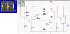
That waveform looks like typical ringing from an inductive load. If your load is a motor or transformer, that’s what you should expect. Notice the large voltages, this can damage your circuit if it is not damped sufficiently.
hello RM..many thanks about the information. finally, i got the square wave with some a little bit change in the circuit. But i got a distortion in the waveform (you can refer to the picture). how to get rid of it? and if you don’t mind can you check my circuit again? for your information, i have set all the potentiometers to 50%.
The diagram looks ok. What voltage is the straight line at? Have you set the position of the potentiometers for the simulation? You need to set them to 50%.
opss sory RMC..so this is the circuit..can you check it for me?and i don’t understand why everytime i run the circuit the output on the load will become straight line. maybe it something wrong somewhere in my circuit.thanks a lot RMC.
You need to crop your image too. There’s too much white space.
Palle B,
Not sure what you mean by “make a threshold”, but I guess your wiring is wrong somewhere. It should work with any IGBT. One thing you might try is to put a 10k resistor between the gate pin and GND. This can help switch off the transistor.
hanyss,
You need to crop your image before posting it.
Thanks RM
I can see that my picture of the schematics has gone lost somewhere i cyperspace?
I’ll try posting it again.
RMCybernetics thanks for the help.
but i still don’t get the square wave. i just get the straight line.
is it because of the problem of my connection in my circuit or something else?
in that picture is my simulation from multisim. can you check it for me?
i was wondering what is the causes that occurs in my circuit. thanks:)
HI i have a problem with my ignition coil driver(for my car).
I have mounted it like the scematic picture shows, but when i pulse the input, it just seems to make a threshold, and the IGBT gets very hot, then i turn of the power, and short the legs on the IGBT, only then it will turn off?
Have i been using a wrong IGBT?(since the circuit should be ok with other IGBT’s)
Or does any of you have an idea, of what to do, to make this work?
Thanks in advance
Palle.
It is a square wave with adjustable frequency and duty.
hello..
i’m really confuse about this project. i already simulate this project in the multisim but still don’t get the expected output.
so can you show me what is the output waveform of this power pulse controller?
is it in the square, triangle or sawtooth signal??
please give me the answer as soon as possible..
thanks:)
Thank you!
Yes.
I would like to use this as a duty cycle controller for an AC electric heating element by using the output from the circuit to trigger a solid state relay. What I had in mind was a fixed frequency of .1 Hz (10 sec cycles)using 1M ohm resitors for R1 and VR1 with a 4.7uF timing capacitor. In this configuration would the duty cycle of the pulse still be variable from 0-100% of the cycle?
Yes, you can use something called a frequency counter. Most of these will not give you a reading for pulse width though. Some multimeters even come with a frequency counter setting but with a limited range.
PS: Thankyou for your kind donation!
If I want to set my RMC ppm to a particular frequency and pulse width is there any meter that I can use other that an oscillascope?
der strom,
Try measuring the current through it, then you will know for sure.
bin,
If you use a microcontroler then there is no real need for this circuit. You can connect pots to a microcontroler and write software so it can vary frequency and duty of the output.
if i want to use microcontroller to control the Frequency or width of the Pulse,how should i adjust this circuit? can you give me some advice? thanks
I may have found another problem with my circuit. My pre-amplifying transistor doesn’t seem to be working the way it is supposed to, if at all. I measured the current output with my multimeter and found that the current from the transistor was the same as the output from the 393. Since the 2N3055 transistor has a maximum gain of 70, and a minimum gain of only 20, is it possible that it is not sourcing enough current?
My pre-amplifying transistor was an NPN bipolar transistor that had a gain of about 120.
Thanks for the help!
–Der Strom–
ahooper,
If you have only a small load on your coil, most of the pulse energy is being reflected back to your circuit. I would suggest using a seperate battery for the load and control circuit to minimise voltage spikes on the power rails.
der strom,
The output voltage from the coil is proportional to the input current. Since the coils impedance does not change, applying a higher voltage will create a higher flow of current.
The current ratings on the PSU’s are not telling you how much current will flow out of them, it is just how much can flow without it overheating. It is quite possible that your 1A supply can put out 10A for short periods or that your 6A one has a high internal resistance. You should measure the current directly as the numbers on the PSU’s will just confuse things.
bin,
Yes.
hi,RMCybernetics:
Great work! thanks for sharing! i have some questions for this work!
can i use this circuit to generate a pulsed magnetic field? the Peak of B=0.66T
Regarding posts 3280 and 3283:
I got hold of a 12 volt 6 amp power supply and connected it to your PWM circuit as an external power source but the arcs emitted by my ignition coil are even less impressive (hot) than when I had the 18 volt 1.1 amp power supply. I understand the 18 volts would increase the output spark length, but does the output current also rely on the input voltage? I have always thought that the input current controlled the output current, and the input voltage controlled the output voltage. Have I been mistaken?
Thank you very much, and keep up the good work with the site!
-der strom-
Thank you for taking a look at that. I decided to simplify things a little and have managed to get the circuit running however it seems to eat FETS and I am guessing this is due to the back EMF being generated.
The FETS used were IRF540 as they are 100V 32A and I have placed a free-wheel diode across them as well as a neon+resistor and an MOV. seems to help a little but not as much as I would have expected.
I will try and RC circuit instead of the MOV and see if that works any better.
Attached is the simplified diagram.
Hard to say, the diagram looks ok. What is the voltage output of the regulator? You should use 12V if you use a FET as these need a higher voltage than a bipolar type. Also more decoupling capacitors might help.
Shipping to NZ is just £6.19 by standard Airmail service.
I must be doing something wrong, I have built this circut a couple of times once on a PCB and once on protoboard but can not seem to get it working with a FET. I have managed to get it running with the addition of another transistor to drive a couple of 2N3055’s but its not exactly stable.
I would appreciate any insignt on this. I wish you guys had a shop down here in New Zealand as the shipping of one of one of your kits would be a killer.
I think that you would need some circuit that will give a pulse after a small delay. The pulse for the injector would activate the second circuit to fire the coil. If you want us to make this for you please give as much detail as you can on our custom electronics form.
Hi,
I would like to use either one or 2 of these units to pulse a 12v, 1.5amp fuel injector and immediately when the injector is closed then somehow fire one spark plug from the coil. It seems possible but I dont think I would have need of the var pots on the ignition as I would just wan it to fire after the injector is closed. Is this possible with this circuit? If so, is this something that you can customize for me? Thanks
Yes there would be a common ground, but having a separate supply means that the V+ that is always connected to the coil, is not also connected to the V+ supplying the control circuit. When the coil is ringing only its own supply sees the extra voltage. You still need some transient protection though due the common ground.
So is the answer just to run the pulse generator from a seperate battery/power source? But if I do this then surely both the coil circuit and the pulse circuit would need a common ground which would lead to the same problem of fried chips.
Thanks for your help.
The problem with driving ignition coils is that when there is no load (or the spark doesn’t fire properly) all the energy you put nto it during a pulse, gets reflectd back to the circuit at a higher voltage. You need to use some MOV’s or zenner diodes to clamp the voltage. Also if you are using a single battery the reflected pulse will partially appear on the low voltage supply to your circuit. Since the ICs are rated for about 15V only, they will be destroyed easily by this.
Hi,
I have made your circuit and used it to drive an ignition coil and spark plug. However, I am having trouble protecting it. I have tried a freewheel diode and a variety of RC combinations placed across the coild but I still seem to be burning out 555s and 393 when I generate big sparks or turn the frequency up. I don’t really understand why this happens – can you help me?
You would need a transistor rated for 80 Amps. The instantanious current is the same, but by using PWM the average is lower.
In your rm post #3580 you ask about current w/o pwm. I have a similar question. Hooked up direct to a 12V battery my HHO electrode pulls about 80A and the water fairly boils. Would this cook a IRF 540? Or does the FET limit the amps delivered to the electrode? Thanx much!
You will need to find a supplier of very high current transistors. They will be very expensive and will need a good drive circuit for making it switch on and off effectively.
I’m thinking electric vehicle motor controller.
How is the best way to scale this up to handle 500 amps peak load at 120 V DC? That would be about twice the power of your super high power unit.
50 IRF740’s in parallel on a very efficent heat sink? or is there a higher amperage transistor that will still handle the voltage? It would be 140V peak operating mostly at 120V driving a DC motor. I havn’t yet figgured out how to search for an availible transistor in the datasheets for a given job.
I have already used the pulse controller circuit as a low power unit to drive the power bipolar NPN’s on a 48V 15HP forklift motor where the control board was dead. That’s in an electric hybred car we built, I have a manufactured EV to repair and resell, and then I want to build another hybred
using a KIA sportage my neighbor is pulling an engine out of. I have an osciliscope to help me play with them, and would much rather build a controller than buy the one for $1500 US dollars that’s avalible.
Either way is ok as long as you cool the MOSFET adequately.
My hydrogen cell pulls 26 amps. So I`m thinking of either building the power pulse modulator using three IRF 740 mosfets connected in parallel or using a single IRF 540 mosfet which I think is rated at 30 amps. Do you agree?
You can add that same switching method. It wass just left off this diagram for simplicity.
Why is it that this circuit does not make use of the 4 pole switch between capacitors of different capacitys like the other low powered version of this circruit does?
Does this circuit still have the full range of the other 0-125k?
It does not matter if you supply less than 10A. The current flow is just dependant on your load an the settings you choose for duty and frequency.
When you say “Input 9 to 12V 10A (120W)”
Does that mean this circuit will fail if I use substantialy less than 10A?
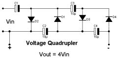
I plan on using this to drive my auto coil for my multiplier
And I further plan on running the whole thing on batteries =P possibly stacked A23’s or perhaps stacked 9 volts depending on the design of my auto coil.
I know this circuit and other designs for high voltage multipliers are made for higher wattages but the truth is I am trying for a design that looks the same as a high powered circuit but that runs on 2-20 watts max and that outputs milli amps at best.
Is this circuit still the one for me or do I need another?
You know the voltage and currents that are to be switched, so you can use this information to look through the IGBT / transistor section of an online electronics shop. Just find one that is rated for higher values that you want to switch. Choose one with a case style that is easiest for you to screw to a heatsink or whatever cooling you wil use.
ok , so what type of IGBT then ? 🙂 thank’s
Use an IGBT instead of a MOSFET. They work better for large currents.
hi rm,
i guess the problem is the mosfet that i’ve used can’t resist the heat caused by my bike’s dc current.
do u have ideas what mosfet i can use as substitute for the small IRF740/530 one.
i mean the UFO like mosfet like here.
i think it have bigger heat resistant
thank’s 🙂
You need to read the datasheet on the MOSFET you use and figure out what sort of cooling it will need for 5A. Your bike chassis is probably not a very good heatsink. You need something made from copper or Aluminium.
The circuit is stable so long as you don’t have really long leads. It also helps to place it in a earthed metal case if there is any source of noise nearby. The DC current that it can handle is determined by the transistor used, the cooling method, and the thickness of your power cables and PCB tracks.
i’m quite desperate for this mini PWM.. i already tried several times but it seems that the MOSFET can’t stand against the heat caused by just 12V 5A my bike’s volts..
i already patched the mosfet into the bike chassis. so the bike’s chassis become the heatsink itself.
my circuit was dead. i haven’t checked up yet what component was died.
i guest the circuit isn’t stable or just can handle small dc amperage.. thank;s 🙁
What voltage and crrent to you measure if you use no PWM at all and just connect directly? I suspect you still have some problem in your circuit or the way you are using it.
A PWM will not increase the gas production. It simply allows you control the rate or production by limiting the average current flowing in the water.
PS: Please don’t add so much space in your messages.
heelo rm,
i finally found the clues.. the IRF530 that i’ve used seems broken.. so i replace it with the 740 ones and it works, also my etched pcb seems have disconected line..
the result of mine tested on 12,4V 3A DC adapter
output
VR1
max = 3.25v
min=2.8v
vr2
max=1.77A
min=0.45A
i wonder why the output voltage drop so much ?
i don’t know the frequency cause i don’t have the osilloscope for testing it.
i use this for my HHOcell but the HHO gas seems not much produced..
my question is how i can raise the HHO gas production using this PWM circuit?
and which ways that will produce high HHO gas, the low frequency or high freq.?
thank u so much.. 😀
I don’t know about your other wires, you can check yourself. The circuit diagram at the top of the page combined with the component datasheets you can find using Google are all you need.
dear rm,
do you have detailed wiring so i can make it correctly ? i’m sorry coz i’m still newbie in electronics especially when using active components
thank’s
hi rmcyber, you mean my mistakes is only the transistor IRF530 connection ? how about the other’s is my wiring is correct according to my scheme?
thank you so much.. i really want to make this mini great PWM 🙂
Yes you can use either of those transistors, but you must connect it correctly to the circuit as shown in the circuit diagram.
It looks to me like your is not connected correctly. Check the datasheet to identify the pinout of whatever transistor you use.
Dear Rmcybernet,
I already use the etched board to make sure the wiring is not wrong again.
when I connect with DC Adaptor 9 V then I check the output current[using multitester]
is about 1.5 A
then I change the VR2 and VR1 and the result is still the same/doesn’t change.
The voltage output is also didn’t change either
I’m using IRF 530 as a substitute for IRF740. can IRF730 be used too ?
VR 1 = 1Mega Ohm. Using big Potentiometer.
My DC adaptor default current for 9V is 3A.
I wonder where’s my fault. Thank u so much for Any help.
No. There are many free ones available. Google it.
hello RM, do you have PCB software that can make the above scheme ?
thank’s
🙂
Adjusting the pots should make a huge difference. Something must be wrong with your wiring.
The IRF740 will get very hot unless you provide a large enough heatsink.
No, the schematics for our products are not available.
hi rmcyber,
do u have a scheme for the circuir that you sold ? especial for this Power Pulse Modulator..i wanna try to make it
https://www.rmcybernetics.com/shop/cyber-circuits/pulse-generators
thank’s
hi rmcyber, i allready made this circuit and i used it on my hho kit and use 12 V DC 5A but then it quickly become hot especially the IC IRF740 even i allready put processor heatsink..
how do i know / test the ciruit if it works ? i change the VR1 & VR2 but it seems no effect..
thank’s 🙂
here
hello friends, i wanna ask for the IC2[LM393] scheme.. where is the pin number on it ? i’m a little bit confuse to connect the pin since the LM393 have 8 pins
and what’s the meaning for + – in LM393 schema.
thank’s 🙂
Yes, but it will be more easily damaged by voltage spikes if you are driving inductive loads.
thanks a lot sir, sir can i use 2n3773 replace for mosfet irf740? Ihanks in advance
Okay, Thanks for the help
Look at the datasheet, look at the circuit diagram. Match the pins.
How would I connect it?
Yes, looks ok.
Hey RMC
Is it possible to use a LM311 ( http://www.national.com/mpf/LM/LM311.html ) instead of a LM393?
Thanks
Yes, it might squeal at the frequency at which it is set. You could try settig it to an inaudiable frequency.
Sometimes poor connections or wires that are too long or thin will make it more noisy.
Hi all. Have built this circuit 3 times now for use with a HHO generator but it keeps squealing loudly is this normal ?. Thanks in advance for any help.
1.1A is not really enough for good arcs. You really need a supply that can deliver about 5A or more.
1M pot controls frequency.
I set up this circuit with my ignition coil and finally got some pretty nice (unfortunately, not very hot) arcs out of it using my 18 volt, 1.1 Amp wall adapter. Then I decided to try it with an old Magneto I got out of an old lawnmower engine. Man!!! Those arcs were HOT!!!
Anyway, now to my question: I assume there is one variable resistor to adjust the frequency and another to adjust the duty cycle. Does the 1 M potentiometer control the frequency? Or the duty cycle? Thanks!!!
Sincerely,
Der Strom
Your 555 dies because of voltage spikes between your power rails. Power your load using a seperate battery.
Thanks for your guidance.I’m sending a
clip of my project with 1 2N3055 with 1 BD139 in darlington configuration.
The Arc is somewhat over than 1 inch.
However that 9 CM Arc that I see from
many a enthusiasts is yet a dream. I
have used 2 100cc motorcycle coils in
antiparallel connection. I have also tried one 800cc car ignition coil but
no good results at all.The 555 immediately breaks(555 seems more stable in antiparallel connection of coils).The P.S. used is 12V , 7.2 A.H. . However MOSFETs driven directly from 555 timer
do not give as good results(Arcs)as
one 2N3055 gives when in darlington
pair with another bipolar.
-: sovan from INDIA :-
Fern G,
If you use some other square wave source you wll need to add an integrator circiot betweein that and the LM393 so that the 393 is fed with a triangle wave.
sovan,
You can replace both bipolars with a single MOSFET and it should work well. Adding a driver IC for the MOSFET would improve efficiency.
Dear RMC, I can’t tell in words what childhood dream has been materialised thru your site. Now I have readyhand HV supply(pulsed) on my little desktop. However I’ve got some doubts. When I replace MOSFETs like IRF840 or so with 2N3055s the circuit doesn’t respond at all (only if there is a driving NPN transistor like BD139 in between the simple pulse generator and the MOSFET.). However 2N3055s work great. I’ve not destroyed a single one yet though I’ve lost a number of 555s. Does MOSFETs provide voltage gain. I’ve heard that bipolars like 3055s can only provide current amplification. In your Schematic you have said that T2 can be 2N3055 or IRF740. That means exat replacement in the circuit. But it doesn’t work. However if I connect the emitter of T1 (in my case BD139) to ground, collector to +ve rail via 470 ohms resistance and output (direct from collector via a 10 ohms resistance to the gate of MOSFET (the base of BD139 connected to the output of pulse generator) the circuit responds to some effect(not bad in fact). Your circuit seems to be a Darlington pair which doesn’t work with MOSFETs (if a MOSFET exactly replaces the 2N3055 in your schematic i.e. drain for collector, source for emitter and base for gate.). Please reply soon. I’m really getting impatient with HV.
NOTE : BD139 connected with 2N3055 in Darlington pair gives very good arcs. (collector of BD139 connected with the collector of 2N3055, emitter of 139 connected to base of 3055, and base of 139 to pulse generator.). Thanks for your benevolent site. -:SOVAN:-
This circuit looks great for what I wanted to do. But I wanted to know other options there are for 555 based timers, can anything else be used instead of a 555 timer?? In my circuit, I dont want to suppress the inductive collapse of the the High induction coil Im using. Can I issolate the mosfet from the IC with optical isolation?? Thanks for any info.
Yes, allthough they are pretty much the same.
Is this circuit better at driving ignition coils then the ignition coil driver?
Yes you could use those transistors. You just might need to add a resistor before the base pin to limit the current drawn from the 393 IC.
Hi RM; working on greenhouse power systems here. (I’m familiar with radio electronics from working with it many years ago)
Wouldn’t TV horizontal deflection drive transistors work OK for the transformer driver? They’re commenly rated 600-800V C-E, I have several from junk TV’s. just pulled a 2SD871 out. I built the circuit above, combined it with another simple 555 square wave generator, and watching the output on an osciliscope. Currently getting 600V at 2W with a defection transistor from a very small TV and I’m getting extreem voltage drop when connected to the application. I think I need at least 100W output at 2-3 thousand volts so I can put up with some current leakage without loosing the voltage. My load has a 7K ohm resistance but is highly variable.
Input needs to be ac. There two pages on this site about this circuit, here and here
not talking to the rah anymore?
der strom,
More input voltage to the coil.
me again thanks for being here i made this circuit put in 12 volts got 12 out what did i do wrong please help
thanks a mill
I built this circuit a couple of weeks ago (I safely de-soldered an LM393 from a circuit board) and it has worked very well for flyback coils. However, I can only draw it out roughly 7mm. Is there a way that I can make the arc hotter and able to stretch out further?
Thank you!
Der Strom
1. Only 2 pins of the pot VR1 are used.
2. This circuit will run from 12V directly without modification.
Circuit looks great. My question is
1) VR1 is connction to ???? – connection is not connected at all
2) I will be using these circuit on my Honda 110 cc bike with 12V 5A battery. Can I use this straight or do some modifications to lower the volatage usage ( now the lowest is 9V) to 3V. What component I need to Change.?
I was thinking to use it for Hidrogen Fuel Cell.
We have a selection of diferent pulse generator circuits.
Hi newbie here . i want to increase my hydrogen cells production, so will try thr above circuit. Can you supply a kit or do i have to order all the bits individually.
alan
hi its me again,thanks for being here. my question is i am building voltage multipliers for my cell and if this works i will apply it to other ideas.i am taking 24volts and quading it 2x which will give me about 400 volts is there any thing i need to do or look out for that would make this not work efficently. any ideas would be great
until next time im
going green!
You are welcome to answer questions, as is anyone.
To: Generator (regarding post #2976)
I searched a datasheet archive for an LM398 and eventually found one for a 54F398LM (I’m not sure if this is the same as what you asked about). It said it was a “Quad 2-Port Register.” It also said it had 20 pins!! The circuit that RMCybernetics used utilizes a much smaller chip with only 8 pins. I have found a few equivalents to the LM393 if you are having trouble finding one. One of the equivalents is the LM2903. You may want to google the datasheet to make sure you have the correct pinouts. Another equivalent, which I have found and used myself is the BA6993. This one has the same pinout as the 393. I hope this helps you, and if it doesn’t, you can always google “LM393 equivalents.”
And RMCybernetics, I am sorry for intruding on your site, and please forgive me for answering a question directed at you.
Sincerely,
Der Strom
It depends how precise and stable you want your output to be. You are quite specific so I would think that a digital circuit would be best as it will produce an exact and stable output.
Using an analogue circuit would mean that your output timing would vary slightly with temperature. You could use a pair of our PWM circuits and an AM Adapter. You would need to adjust to the output you need and measure with a scope. If you want the digital version for precision, we can build it for you, just send your requirements to our custom electronics dept.
Im looking at this circuit/kit
but I need 30hz output with a 500microsecond pulse width…turned on and off every half second.
Also need to be an output of 3-4volts and current limited to 10-12ma
What would I need to change in the circuit/kit to get those results.
Cheers
Lost,
Use a smaller capacitor for C1.
Generator,
I don’t know what it is but I doubt it will work. You need to use an LM393
What is a LM398 and can I use it instead of a LM393
would like to get a range of 8KHz-260KHz any ideas
No, not unles it is very low frequency. Hydrogen forms positive ions and Oxygen forms negative ones. DC is used so that the elctricity pulls the H2O mollecule apart by pulling the Hydrogen to the negative wire and the Oxygen to the positive.
oh yeah, i added some plates to my cell stop the heat THANKS A MILL!!!! now i need power i am making your ppwm should finish soon ill let you know what i find
hi once more,the info that i have recieved has been more than helpful THANK YOU!!! my now question is can you run a hydrogen cell on AC if not why?
You can decrease the resistance of your cell by using one or several of the follwing methods.
1. Decreace the spacing of your plates.
2. Increase the area of your plates.
3. Use a soluble compound or catalyist.
If you add a substance such a salt, it will make a huge difference, but you must choose the supbstance carefully. Salt will masivley increase gas production but you will also begin forming other very nasty gasses such as Chlorine. Ideally you would use a catalyist (something that increases the reaction but does not become part of the reaction) Potassium Hydroxide or Sodium Hydroxide might work.
hi me again,love this site question how can i decrease the resistance of my cell i fired it up yesterday got great production but it melted my pvc lid. HOT!!!!!!!! right now my cell is at 70K
thanks a mill
The basic idea is that the amount of gas produced is proportional to the charge flowing between the plates. This means more current = more gas. There are several ways to increase the current..
Increase the voltage or decrease the resistance. I = V/R
Changing the frequency may help if your system is somehow frequency dependant. Most are not.
Hi its me again,as always i love the fact that you really respond thanks!!!!
but my question is i installed my cell in my 1985 chevy pickup i got pretty good production,man i was just wondering would i get more production with voltage or frequency i think voltage.
thanks a mill
If you add resistance to limit current you will just drop the voltage across the resistor meaning a lower voltage for your cell. You need to increase the spacing of your electrodes.
Hi again as always great site! my question is i want a simply current limiter for my cell it is running 15volts 20 amps and 70k would like to keep or increase voltage but the amps are making the water boil any ideas
rah2son,
You can get up to 2MHz from some 555’s but you would need a different circuit. At that frequency you would also need a high speed comparator that works faster than the 393.
The voltage you can switch just depends on the output transistor used. The IRF740 used here is rated for 400V. To apply a higher voltage you would connect the + terminal of the load to your higher voltage source.
Chase_Easy,
The orientation of the pots here just determines which direction you would turn them for increasing or decreasing the respective parameter so you can use them either way around. Yes that pin is left unused.
Hi there, great site! I’m curious if you have a PCB layout for this circuit, or a little more detail drawing? I’m confused with the direction of the potent’s. Is the arrow into the back, or is there a general rule for pos/neg of the pots? It looks like the 1M pot pin 3 goes no where, is the pin not used?
Hi rah again,Great site my question is can a PWM be made to produce higher voltage and higher frequency and still use the 555 timer and how
thanks a mill
rah2son
No you cant realistically do that. You would need to buy or make something called a DC-DC converter. It will contain AC and a transformer but it will convert low voltage DC to high voltage DC.
hi i want to say i love your site very informative!!!!!!!! my question is i want to power my hydrogen cell with some high voltsge DC without a transformer or any AC is this possible and can you point me in the right direction or write me a schematic this will be for my car
thanks a mill!
rah2son
Up to the rated voltage of the IRF740 (400V) but you should keep it well below that for saftey reasons.
If I use separate voltage for generator and output, what is the voltage range?
Voltage range for pulse generator, and min. and max. voltage for output across IRF740?
Does it depend on voltage level of pulse generator?
It depends on the 555 used. The reset pin is active low and should be connected to V+ if necessary.
I was just looking at your circuit and have a questions.
On the 555 timer, reset (pin4) is not connected to anything in your circuit? why is this? I believe that the reset on a 555 is active high so shouldnt it be tied to gnd? Also, what about the control voltage (pin5) or can both of these be left unconnected without affecting opperability. I have built a circuit similar to this one using a 555 timer and 741 op-amp comparator and in order for it to work, it was necessary for pin 4 to be high and a .01uf capacitor be placed between pin 5 and ground.
All these years of elec engineering and I never really messed around with 555’s at all….
hello
i need to run a coil for flamethrowers. my truck is a diesel so i need a pulse controller. i have the ability to build this, but im clueless to the language. what do i need to do to build one (in idiot language lol) i need a 12V source to pulse as fast as possible. please help me! lol
thanks!
jeff
chris,
No, you can use a MOSFET driver after the 393. The 393 is needed to perform the PWM.
traveler,
Yes, Place them in parallel. THe disadvantage is that the wave becomes less square with each one you add.
i have a well, stupid question. is it possible to use more than one of the irf740’s it increase the amperage possabilities/capasity in this project?
love the circuit , but can you use a
ic7667 n channel mosfet driver for ic2 ?
my 555 is running at 98hz with the 7667
and it shows on the scope running well
but when fed into a power mosfet rated at
1200v 30amps , i get nothing ?
why is this ?
im stumped
any suggestions
thankyou !
Good day
I am busy building a Marx Impulse Generator and struggling to locate the pins of my Flyback Transformer.plz help!ZTFK82003A
A Triac will cause poor performance because it only switches at 0 crossing. The output of an ignitioncoil is proportional to the rate of change of current. i.e. swich off as fast as possible. The kickback voltage is not avoidable if you want good sparks as it is inherent of the physics used to create the spark.
Hello, I have used this circuit on an ignition coil but usually get IRF failure quite quickly even when using filters (MOV and caps). Optimal frequency is about 1kHz. I tried using a dimmer circuit with a “snubberless” triac circuit (BTA12600CW) (cuts at zero crossing, avoiding kickback) with line voltage (220V0 but performance is poor (thin spark) possibly because the optimal frequency is not reached. Would it be possible, in your opinion, to use a 1kH AC source and switch that with a snubberless triac driven by your circuit? This should avoid kickback altogether. many thanks. Sorry for the slighly off-topic post!
HighDessert,
The power input connections of the second circuit would be linked to the output connections of the first.
Unknownjarg,
No
HI I would like to know if this controller can be used to slow down or speed up an existing 12v dc pulse . Thanks in advance unknownjarg@hotmail.com
In message response #1952 you suggest using 1 circuit to power another. From what point to what point would this connection by made? Also, please talk more about double and multiple pulse circuit design. Thanks, this site rocks.
Yes, it can be set to between 0 and 100% of the length of time between pulses.
Will this circuit control pulse length as well as pulse frequency???
Thanks, great site btw!
It will work with 15V an no mods needed. This too.
I am looking for one of these to run on a hydrogen generator on my car. Can this handle up to 15v input? What modification could be done to do so?
Thanks!
-James
Depends on your 555 chosen. Some go up to 2MHz but the 393 will not work fast enough for that. You can get a good square wave to about 100kHz, then it becomes distorted upto about 250kHz, after which you will need to add extra components to make the signal useful again.
What is the variable frequency range of this circuit?
No, the diode is to protect against reverse voltage that may be produced in the load. About 100nF should hive you that low frequency range.
The pots should be the values shown then adjusted to give what you want.
me again,what sorta of values should teh 2 vr’s be to give 75% duty cycle @ 12v and 100 hz with the given capacitor i asked about before
many thanks
doesnt the diode just allow the input voltage to go straight to the output? what size capacitor should be used for ~10hz-10khz
1. No. It is not designed for use with square wave power.
2. Yes, the filtering works in both directions. You don’t need to connect it backwards. Connect the NST to ‘load’, and mains input to ‘line’.
Hello, two questions about your “EMI Line Filter 20A 115-250V AC“. 1. Would it work on the DIY pulse driver to avoid back EMF from the ignition coil? I see it is rated at 48Hz – up to which frequency does it pass signal? Unfortunately the ignition coil is working best around 1000Hz so I guess it won’t work. 2. I may also use one for protecting mains from a NST – should it be connected “backward” e.g. mains on load and NST on “line”, since I will actually be protecting the mains from back EMF from the NST? Many thanks
No.
could you post the new circuit with the optional combined hookups and AM control hookup or email it to me in a .pcb or eaglecad file to (email deleted)
You should ask Velleman. I would think that that MOSFET you mention is not rated for enough current for any sort of welding.
I bought a Velleman PWM Kit and I want to know if I can substitute an Internat Rectifier FA57SA50LC Mosfet for the little one that comes with the kit so I can Discharge a Capacitor Bank and hopefully make a Capacitive Discharge Spot Welder. I will use a LARGE heat sink for sure. Thank you for any help.
Neither will help. Your fence gets hit, the circuit gets fried, it’s that simple.
You would need to set up a lightening rod that would take the strikes instead of the fence.
If you are making an electric fence, the circuit needs have its GND connected to an earth rod anyway.
hello
how should i protect this circuit from lighting/thunder if i connect it to a fence (sort of electric fence)
pls help. can i just connect earth to the circuit ground ? or at groud of the coil ? with 1 better ?
C1 can be either of those. Any non polarised capacitor is fine. Its voltage rating should be anything above that of your supply voltage.
Snubber capacitors should be multilayer or something that can handle a litle power.
If C1 should be ceramic or multi layer type.
What kind of Capacitor should be use as snubbers ?
How to know the volt value for the ceramic/multi layer type ?
thanks
I think that should be ok. I wouldn’t expect much of a problem with voltage spikes because the transformer will be loaded with the hot wire.
Hi, very very good site and thanks for patiently answering so many questions.
I hoped I might use this circuit for driving another step down transformer to give about 3v at 15 amps max output to a resistance wire cutter.
Do you see any problem with this idea and would I need to protect the output of your pwm circuit? Thanks Graham
Yes, It is mentioned a couple of times allready. See here and here
hi sir,
is it possible to use another device stead of lm393 for example a simple comparator in electronic workbench(for simulation)?
thanks alot for the quick reply
bnzd123@yahoo.co.uk
Ok so i finally got my pic resized (sorry im lazy) but here it is!
Yes it will.
RMC,
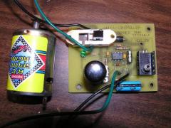
Yeah sorry I forgot about size. I will convert the image sometime today and upload it. The motor which I mentioned draws 1.35 amps @ 7.2 volts. You mentioned that the power pulse modulator will output up to 10 Amps of current, so can I assume that the circuit can run this motor?
Thanks for your help.
tomu,
I can’t give you a direct replacement, you will need to search yourself. There are potentially hundreds that will work. It just needs to be a low offset comparator for use with a single voltage supply.
Chris,
Your picture will only be accepted if it is a jpeg (.jpg) and less than 200kB in size. The device mentioned will drive motors up to 10 amps.
Can this Power Pulse Modulator power this motor? I havent gotten the specs yet, but I will find out this afternoon. Thanks for the quick reply!
what is the equivilant to a lm393 chip?
thankyou for taking the time to answer my question although some people abuse the privilage by asking questions that could be answered by googling lol thankyou great site by the way.
dexter,
Its getting hot because too much current is flowing through it. You can reduce the current by either lowering your supply voltage or increasing the resistance of the circuit. Insert a resistor (about 100 ohms) between the power supply and the IC’s power pin.
Chris,
If the motor is physically larger then yes it is likley to have overloaded the circuit. Our PWM circuit will work with large motors.
Hey RMC,
I recently bought a motor speed controller using a LM555. After completing the kit, it ran the included motor just fine, but when I connected my own DC motor, it would not move at all. At first test, nothing happened at first but then there was a burning smell and a pop. The LM555 was hot, so I thought that was why it wouldn’t move that load. Is that the reason or is it because my motor draws too many amps? (sorry i don’t know the specs right now, but i will test the motor tomorrow and find the amps). I have attached a picture of the speed controller and the motor which I wish to drive.
I have built this circuit, but instead of a 393 I used a lm2903, looked the same, and at c1 added a multi position switch so I could pick between 4 different values of capacitors. My problem is that the 555 is getting hot within about 20 seconds of operation. I am using this circuit for an electrolysis project. I have gone over the circuit to check my connections and everything looks good, can you help me out?
Thomas,
Yes fortunatley the IRF740 is avalanche rated, meaning it can tollerate such a breakdown if it is only temporoary and within certian limits. Unfortunatly driving an ignition coil with a variable frequency and little or no load on the output will produce lots of back EMF. Imagine the flow of energy in the circuit as if it is a wave. It flows into the primary coil and then from there into the secondary coil via a changing magnetic field. As this energy reaches the output terminal of the coil it sees a huge change in impedance (low in the metal coil to very high in the air). A change in impeadence always causes reflections of waves. This means the energy wave is reflected back into the coil and eventually back to your transistor.
You either need to absorb/dissipate this energy before it hits the transistor, or you need to allow the wave to flow out of the coils output. Once an arc is formed there is a low impedance and energy is not reflected much, but before it forms the air has a huge impedance and causes lots of reflection.
If you are not concerned so much with varying the frequency or voltage then you can use some sort of self resonant or even mechanical oscilator.
tomu,
Square, it will distort and become rounded at higher frequencies.
No. The FET does not effect the input voltage you use. The voltage appled must not exceed that of the comonents ratings. Obviosly the 400V of this mosfet is fine, but the 555 and 393 have lower tollerence.
what is the wave form produced?
and if i use a bigger fet vds = 600v then can my input voltage 12 be upgraded to 24+
Found the flybacks on eBay. Hooked the Pulse Controller to a real ignition coil. Get some nice corona, but all my neons lamps are lighting up (including the one with a 270k resistor, which is supposed to kick in at 220V) and the 200V MOV gets hot. Then the circuit stops working for a few seconds – I assume this is the MOV shorting then getting back to normal? I am out of ideas for snubbers… Is there any circuit that could keep the coil running for a long time without shorting?
Got it cheers, where did you find these transformers? The typical neons will light at about 90V.
Good point… I will add two more neons with different resistors to see if there is a cutoff. Since my neon is lighting up with its 1K resistor, can I estimate the value of the voltage spike? Is a neon lighting up from a specific voltage/current? Cheers
Shipped the flyback to you today BTW
newbie,
It should not be so low. You must have an error in your circuit but you will have to figure it out yourself. 4V is too low. 10V is a typical value for switching a MOSFET.
Thomas,
The resistor values normally used for the neons are chosen so that they can be lit constantly from the applied voltage source. In this case they only light briefly and we also use them to dissipate some energy. This is why the resistance value is significantly lower. If the voltage of the spike is high a larger current can flow through the neon and therefore more energy is dissipated as light and heat. The second neon will not light because the other snubbing devices are preventing the voltage from rising high enough to power the neon through its resistor.
Added filter with (all 4 in parallel)
-60 nF 3000V cap (18 3.3 nF 3000V caps in parallel – I had a lot of these!) with a 10K resistor (1W) in series,
-a MOV (200V)
-one neon (Maplin RX70, I assume 0.8 mA since for 220V needs 270k resistor) in serie with a 1K resistor
**basically the three items described for the ignition coil driver.
-a fourth neon ((Maplin BK53H, “built in resistance for 220V”)
The first neon (Maplin RX70) lights up. The second neon (BK53H) does NOT light up… am very confused now
I am using a 9V NiH 200mAh battery for this – using a PSU 16V 4 A max fried my IRF740 yesterday
hi. thank you for the suggestion. i followed it and it was a square wave for the gate pin. however, it was at a low voltage. more or less at 4V only. (under 9-12V supply) what do you think is the problem? Also, is it possible that my IRF740 is not turned on at such a low input voltage at the gate? Maybe my power supply is not that good? Should i address this insight? Thanks so much. Big help.
Sometimes the voltage spikes can be to quick for the MOV to respond. Maybe a neon bulb with a 1k resistor in parallel with load will give you an indication of when the voltage spikes are dangerously high. Does the rest of the circuit still function? A HV diode will drop too much voltage and is useless in a low voltage circuit. The one I linked to above drops <40V. A High amp diode with low enough voltage drop would be destroyed by the spikes. You would possibly need to employ one of the other snubber methods shown on the ignition coil page
Thanks… indeed the sound stopped when the IRF died. I used a MOV with 209V min breakdown Voltage and 388V max clamping between Drain and Sourge, so I assumed it would be okay. Also, I was measuring the amps when the IRF fried – it was about 1.4 amps. BTW would a high V high A diode in series from Drain to Load stop some of the spikes? I think this is used for small inductive load directly driven by a 555. cheers T
newbie,
Start with a low frequency, measure the signal on the gate pin (pin 1). This should be square and at a voltage just below your supply. If its not, remove the IRF740 and set the point which was connected to the gate pin. If it isn’t square, then your circuit is wrong somewhere an you will have to just recheck your wiring. if it is square until you put the transistor in then there’s possible something wrong with the transistor or the way you wired it.
Thomas,
This is happening because more than the rated current is passing through the device. I doesn’t matter how big your heatsink is if you allow too much current to flow. When this occurred did it stop making sound (at the frequency of your drive circuit)? If so, this means the mosfet or other component was damaged by a voltage spike which caused it to permanently latch on therefore allowing the full current to flow through and melt it. See the ignition coil driver page for info on voltage spikes. Sure, I’ll try out one of those xformers, I’ll send u a couple of HV caps and diodes in return if you like. email us for the address. Cheers
The circuit works… but when I tried drawing more current by tuning VR2, the IRF740 started to glow red (a spot between Drain and Source) then died! it is on a large heatsink (6C/W). What am I doing wrong? I have attached a pic of my small flyback. BTW if you would like one of these to tinker with, I’ll send it to you for free – you’ve helped me a lot Thanks Tom
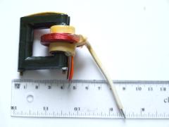
this is the signal in the 2nd pin of the IRF740.
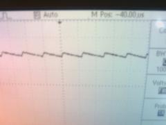
hi, it’s me again. i corrected the direction of my IRF740. i even replaced it with a new one just to be sure. it’s still not working. i’m attaching an image of the revised circuit as well as the signal in the drain pin of the transistor. i really want to make this work. thanks for the help.
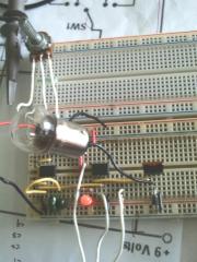
If the bottom row on your breadboard is for GND, then it looks as if your IFR740 is the wrong way around. Just rotate it 180. Here’s a link for the IRF740 Data sheet
i followed the circuit diagram above, however, when i connected it a light bulb as the load, it did not even light up. I am sure that the signal generator part is working (checked it using an oscilloscope and i used the circuit with pulse width modulation). the problem is in the IRF740. i don’t what i’m doing wrong because i rechecked everything. HELP! I am attaching an image here. hope you can see what’s wrong!??
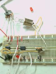
thanks!!! 😀
this site is really helpful! 😀
Yes. C1 is any non-polarized type like ceramic, mylar etc.
hi! i am planning to use this circuit in driving an electromagnetic coil. i want to introduce a time varying current to the coil so that i will have a changing magnetic field. will this do the work for that purpose?
also, what kind of capacitor is C1? is it electrolytic, mylar, ceramic..etc?
Yes, that should help protect your MOSFET between its gate and drain terminals. You might sill want to protect the gate pin (between gate and gnd)with a smaller aster device rated for a low voltage.
Great, very clear as usual. For this circuit, would a http://uk.rs-online.com/web/search/searchBrowseAction.html?method=getProduct&R=4864599 with 209V min breakdown Voltage and 388V max clamping voltage be okay? The 388V being under the IRF740 specs (400V), it should keep it protected?
I tried to make it, but it ain’t worked. Maybe my LM393’s are dead. I will order new one’s. I will keep you informed. And another thing, should I connect MOV between the lm393 output and gnd or parallel to load. You helped me a lot. I have already made a Tesla coil with my old
NE555 driver, but I want to make a new, just like that one on this site.
Thomas,
Maximum clamping voltage is the highest voltage that you can expect the MOV to keep between its terminals. If this value is 200V then you would not expect to see any voltages over 200V in your circuit (as long as it is used correctly).
The minimum breakdown voltage is the lowest voltage at which you can expect the device to begin to activate. If this value is 200V then your normal operating conditions must not reach this value.
CrazyMadMan,
Not exactly, but for this circuit it will not matter.
Pin 3 of the 555 outputs a square wave, there is no point in feeding that into the comparator and that is why pin 3 is not used in this circuit. If you have a 555 and a 393 why not build this circuit?
Are LM393N and LM393P the same as LM393?
I made an oscillator with NE555 and when I
connected ne555 pin3 to lm393p pin3, and other ( pot, v+,v-), voltage on output pin 1 and gnd was 0. I connected all properly. What do You think?
I am a bit confused with MOVs now – what is the difference between the minimum breakdown voltage and the maximum clamping voltage?
RS have lots of bidirectional MOVs. Even in the hundreds of volts range.
The cap and resistor combination used for a snubber is usually chosen to be the largest capacitance you can use with acceptable losses in efficiency of your circuit.
We are currentl out of stock, but we should have some available soon. Check the high voltage surplus page
Thanks for your explanations on the MOV. The 18CA will be between output and ground. I could not find high voltage bi-directionnal MOVs (at RS) – would a unidirectionnal be okay, and in which direction should it be connected? Should I use 2 in opposite dierctions?
Also, how would you test for best capacitor to connect across the load? I have heard that ignition coils usually operate best around 300-1000 Hz, so should I just put in a cap that starts conducting around 10 kHz?
Would you have any ignition coils that work well with this circuit for sale? My ignition coils always give pathetic sparks with either this circuit or the 2N3055 one. Many thanks!
CrazyMadMan,
The datasheet tells you it can. The circuit here with a 393 allows the pulse width to be varied independently of frequency and it will co from 0-100% just from varying one pot. A 555 on its own can not do anything like this.
Thomas,
1.5KE18CA (MOV) would be ok on the output of the 393 like you suggest, but if you place it across the load it might heat up and be destroyed. It would also reduce the efficiency of the circuit.
This is because every time a spike goes above 18V (which will be almost every pulse if the ignition coil is not heavily loaded) all the power meant for the coil will go through the MOV for that instant. If you want a MOV across the coil it should be rated for hundreds of volts so it just clips the top of the highest spikes so they are within the voltage range of your transistor.
Any capacitor across the load should be rated for at least 1kV. The capacitance value would depend on the frequency you operate at. Higher frequency, smaller capacitance. You will need to experiment to find a suitable value. you should also place a resistor in series with this capacitor.
Yes, all power carrying cables should be thick.
Hello, I am almost done finishing this circuit to drive an ignition coil. For suppressing spikes I am planning to use
** a 1.5KE18CA transcient voltage suppressor diode: SHOULD it be across the load, or between pin 1 of the LN393 (output) and ground, or both?
** a capacitor across the load – WHAT value (nF, Volts) would you recommend?
Finally do you use a fat cable from ground to source of the IRF740? It is going to handle a lot of amps?
Many many thanks – Thomas
I found this circuit in NE555 datasheet. Can it be used for pulse width modulation? Is it better than LM393? What do you think?
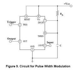
Yes. Almost any NPN transistor with similar properties (read its datasheet). It needs to be able to handle about 1 amp
Can I use some other transistor instead BFY51 and which, for audio modulation?
You can limit the current using a large power resistor in series.
You can still audio modulate the spark but you will always have the sound of drive signal. The drive signal should be as high as possible because it will only allow for accurate modulation by frequency’s which are half or lower than it.
How can I limit current through 2n3055?
My induction coils can’t create sparks at inaudiable freq. so i can’t make audio modulated spark? Please help, it’s for my school project.
PS. This site is the best!
No. its a 393. You can use almost any single supply low offset comparator
did you mean LM339 quad comparator because radio shack doesent have a LM393 lol
Yes it would, but you would need a suitable resistor to limit current or just connect the drain pin of the MOSFET to a seperate low voltage supply instead of the main supply rail.
(PS. I deleted the specs you posted as they took too much space on the page)
Would this circuit be suitable for driving a 2.8v 500mW 808nm laser diode?
(Edited by RMCybernetics)
The drive frequency needs to be adjusted to match your coils for best performance.
What voltage does your input signal reach?, It typically needs to reach 10V to switch a MOSFET on fully but you can sometimes get away with voltages as low as 6V.
HI and thanks for all information.
I’m building my own coil driver using 2 IRF 530 (100V/17A) driving 2 antipararell coils. I,m using a commercial signal generator to drive the IRF:s (through a 180 ohm resistor) And I have enough power (12v/20A) But.. The circuit only draws 0.5-0.7 Amps and the output voltage is roughly 15-20kV. I expected more. Any suggestions anyone?
See the ignition coil driver for protection methods.
you will need less than 235nF to get higher frequencies. 235nF will give a range of about 1Hz – 600Hz.
You can also increase the frequency by reducing the value of R1.
can i put a condenser across the output to protect the circuit from back emf? can i use two series capacitor with a value 470 nf to beef up the frequency? thanks
IRF540 will work fine as long as you are not diving highly inductive loads such as ignition coils. It has a voltage rating of just 100V compared to the 350V of the IRF740 so it will be less tolerant to back EMF.
Hi there, love this page. Has been a source of great entertainment and education. In NZ some components are hard to get hold of. Namely the IRF740. Would it be possible to use an IRF540 instead? Thanks.
kent,
Lifespan will depend on your load. Most MOSFETs will do if they are rated for more than the voltage and current you will be using.
mark,
See the ignition coil driver for protection methods
if i was to add a microwave cap in parrallel with the load wires of this circuit with a 1k resistor will this protect the circuit and ohh yes 6amp diodes as well but im not sure how i should wire them up
will this circuit have a long life span and can any mosfet be used if the vds is 4 x that of your power source thank you
Pulse width setting is as a percentage of one cycle (duty) therefore with a fixed duty of 50% for example, the pulse time would vary with the frequency. With two units you could set one to give a 10ms pulse at a low frequency and use another one to supply that one with its power. This would give you fixed 10ms pulses the frequency of which could change with the second unit. You could also use this setup to give double or multiple pulse bursts.
Hi. I have been looking at the power pulse modultor kit. My application requires a fixed pulse width (10ms) and a varible frequency (0-50hz). When adjusting the frequency will the pulse width stay fixed? Also can the frequency be controlled with an external variable 0-5v voltage source? Thanks in advance for your assistance to a newbie.
Probably not well. It needs to be a high frequency. Please post your coments on the relevant page. Your question should be on the plasma globe page.
Would this schematic work for a plasma globe?
Once again, thanks a bunch for all your help 🙂
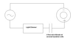
Solid state TCs usually use an IGBT. Your question does not relate to the article on this page. Please post relevant comments/questions only.
rmc , do you have plans for a high voltage switch , im building a solid state tesla coil running off a square wave and the power supply is a rectifiyed flyback producing dc up to 400 or more volts but i need a high voltage switch which will not effect frequency. do you have plans for this? signing off man cups are weird
Yes you can add decouplers as you suggest. You mention “the 100 microfarad capacitor” but there is not one on the schematic. I assume that you placed one across the power rails to act as a smoothing cap. You would not want a resistor with this.
Use a MOV (varistor) pull any voltage spikes down to ground.
You probably shouldn’t apply 15V directly to the circuit as it is shown because there are no resistor protecting the ICs. You would need to place a resistor between the ICs V+ and the +15V to keep the voltage within the manufacturers ratings. 15V is within the rated input range for both ICs (555 = 16V, 393 = 36V), but it would not be good practice to run them so close to the limits without some sort of current limiting resistor.
thanks in your reply, i will check my circuit connection and hopefully find the culprit, can i add a decoupling capacitor between pin 8 and 1 of the two ic’s and a 100 ohm resistor in series connected to the 100 microfarad capacitor and input supply voltage to protect the ic from unwanted voltage? can i use 15 volts power supply in this circuit? thanks again
Clearly it’s not working. VR1 and VR2 should make obvious changes.
If your fan is stuck on full speed it means that either there is a short circuit which bypasses the transistor, or that the oscillator is not oscillating and is stuck high causing the transistor to be switched on permanently.
i have build your circuit and i want to use it for driving a fan, but i can’t find any change in fan speed even varying vr1 and vr2? Im new in electronics. can you help me know that my circuit is working? thanks
It’s possible the voltage spike is on your power rails. You could place a MOV across your supply, but make sure it has a good response time or it could latch on and short your supply.
Another way is to place a reverse biased zener diode or MOV between the 393’s input and ground.
You could also use the spare amp in the 393 IC as a buffer for increasing its output impedance.
Most of these methods may have some small effect on performance such as increased switching time caused by extra capacitance.
It’s also worth noting that using a battery as the supply means that your ground connection has limited current sinking abilities therefore it’s not always going to stay at 0V when the circuit is active.
this controller is really good, i can easly draw arc with 10v input.(with quite a few lm393s fried lol) Thank you ! Rmcybernetics
i did the following to protect the circuit.
1. 1n4007 to lm393
2. 10nf@1kv cap also included across D1
3. a small cap and a MOV across the input of the ignition coil
i dont know if it is enough but i haven’t fried any 393 to now 🙂
do you have any other suggestion that i can protect the lm393?
Oh goody goody! I was hoping that my intuition would prove correct, thanks very much!
Yes, but you would need to connect the drain pin of the transistor to a seperate lower voltage source or just drop the extra volts across a resistor.
Greetings All!
I’ve been toying around with the idea of building this controller since I came across this site a few months back, and now think that I may have a valid project for it.
However, I wanted to seek out some advice as to whether or not this particular pulse controller is suitable to drive high (approx 250mW, 3v, 150mA) output laser diodes. If not in its native form, do you guys think that it would be feasible to change the component values to be more suited to these types of laser diodes?
Thanks for your input!
Hello, I’m curious as to whether or not this device is suitable to drive laser diodes?
Yes. Any 555 timer with the same pinout will work.
Hi!
Thanks for this grat project!
I’m just wondering if that LM555 could be replaced by the ordinary NE555. Because the former one is quite absent at my location?
The power pulse modulator has built in protection against electrical spikes.
Driving an ignition coil without any load on the output may cause very large spikes. The PWM-OC10A will indicate when the back emf is too large. The simplest way to reduce back emf from an ignition coil would be to load the output (i.e. place a capacitor or resistor between the output of the coil and GND). Alternatively you can place a capacitor across the two input terminals of the ignition coil. The larger the capacitance of the capacitor, the larger the snubbing effect will be. This type of snubber is dissipative and therefore reduces the efficiency of your system.
Further to my message yesterday re the pulse generator in which I asked for data regarding protection against electrical spikes. I neglected to ask you to tell me how to connect this item to the pulse generator. thank you for your patience
Yeah, I guess so. The power pulse modulator would allow you to link to an analogue sensor quite easily for automatic control.
Thank you for posting this project!
This looks like it could be useful for driving automotive fuel injectors in an “extra injector(s)” setup (I.E. to add more fuel only when need as in turbo boost mode activated by a boost pressure switch). Do you think so?
You can drive a step up transformer to give 400V pulses from a 12V source.
The MOSFET used is rated to a maximum of 400V so you could also use it to switch a HV source.
Can this circuit use for generating high voltage such as 400V pulse by switching a high voltage source?
Thanks,
We don’t currently have any HV caps for sale. eBay would probably be a good place to look.
Thanks for your replies. Those DC-DC converters are high voltage (even greater than 10KV) and they are advertised as for also charging capacitors, which is where my interest lies.
By the way, do you have good high voltage capacitors (>=3000V) for sale? If so what’s their cost? if not where can one get some at good retails prices?
Maybe 15 is the + pin, I don’t know for sure. It will work either way around but it’s better if it’s correct. You could try measuring the resistance between the output and an input pin. The pin with lowest resistance is GND but it might be hard to measure the difference.
The Atlas LCR is pretty handy for measuring inductance, capacitance and resistance.
I use a Brandenburg high voltage meter which is basically a big voltage divider and a panel voltmeter.
To measure the output of an ignition coil I use a rectifier and capacitor so can measure a DC voltage. It’s typically 20 – 30 kV from a big 12V SLA battery and a coil driver.
Those DC-DC converters are handy for low power and voltage but they are not good for things like Jacobs ladders and Tesla coils like ignition coils are.
Thank you very much for your response. My problem is, however, there are no apparent marks or indications on the ignition coils that will elicite a guess as to the polarity. But may be the numbers, for example, 1 and 15 written against some Bosch ignition coils could mean something, do they?
What Inductance meter would you recommend?
Also what do you use to measure those very high voltages? What are the normal voltages one can expect to get from 12V Bosch ignition and flyback coils, for example.
I would also like to have your opinion on whether one can use PCB mounted DC-DC converters as shown here, (http://www.hitekpower.com/pcbmountdc.htm), for example, thereby eliminating bulky ignition or flybacks if one’s design is not very high current or power?
Best regards.
Similar coils can be found attatched to the spark plugs in some cars such as a Renault.
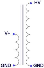
The wiring is represented in the diagram here. The pins marked GND are connected together inside the casing of the ignition coil. Finding the polarity of the coils can be done with an inductace meter between the output and an input pin. The pin with the lowest inductance is the GND pin.
I tested the flyback you mentioned by simply connecting a Power Pulse Modulator to pairs of input pins and measured the output. By process of elimination two of the input pins were found to create a good output when being driven by the 12V pulses.
Hi RM,
I was looking at your small ignition and liked what I saw but I believe I am living in a place far away from you to make it impractical to want to buy and get sent one of such coils, so I think I’d rather ask from which scrap equipment can one get such small ignition coils?
Also how does one determine the polarity of ignition coils when they are not indicated on the coils?
Again, I saw a flyback for sale on the same page, I have similar flybacks for projects I’d like to undertake, but how does one determine between the leads; which is primary, secondary and feedback coils leads when there is hardly any indication on the flybacks?
Thanks and keep up the good work.
BDSD.
dear rmc sorry im not on the topic but i have discovered somthing cool that i would think lots of people would like to know how to build.

using a tv you can make your very own ossiliscope by simple disconnecting the vertical defelctor and using that coil as an imput signal.
this is showing no signal and the vertical can clearly be seen.
There are now some Power pulse Modulators on sale on our cyber circuits page.
They provide all the features of this circuit and include extra features such as transient voltage spike protection and indicator.
These devices make an ideal compact yet powerful adjstable power supply or pulse controller. One of these circuits will help you with a huge variety of science and electronic projects. Get yours here.
R3 is used as a ‘pull up’ resistor so that the voltage level is high enough for the MOSFET gate pin.
Thanks for your recommendations re PCB software. I’m trying out Diptrace at the moment and I’m getting on ok with it. I’m a novice in this area :^). Can you tell me what function resistor #3 serves in this particular circuit (Power Pulse Generator)? Understanding the functions of the various components helps me to work out how the thing works. Many thanks ZS
I personally use Altium Designer but this is very expensive as it can do far more than just PCB design. I think the popular choice for home users is Eagle or Protel. I have not really used either of these so I don’t know how well they work.
Thanks very much for the circuit design and great info. I’ve looked at a few 555 and other circuits with adjustable frequency and duty cycle and your’s is the best.
I intend to use the circuit in a similar, high voltage research type project and would be happy to share my findings with the list.
I’m wondering whether you have any recommendations for PCB design software? It would have to be something that’s fairly easy for the likes of me to use.
Many thanks ZS
‘Back Order’ is just used to show that it is out of stock and that the item will be shipped when available.
Just go to the cyber circuits page and use the ‘back order’ button to add the item to your shopping basket. It works in the exact same way as buying any other products the button is just different. Once you complete the order I will get one made and shipped asap.
thank you for your reply to my enquiry I wish to order one ready made power pulse controller is this message sufficient to do that? I am not clear about what “back order” means.thank you
Jack2:
I have not yet sent out any newletter because there has been some delays in getting them made. The kit versions are available now in the Cyber Circuits section. If you want a ready made one, you can back order them and I will make them to order. The newsletter will go out when I’ve got a batch of ready made ones available.
hootsnboots:
You are exactly right. The duty cycle part works by simply comparing the oscilating voltage to a voltage you set with VR2.
just having an uneducated guess here but is this correct. ic1,c1,r1,and vr1 are the timing circut where as the rest are all for the width modulation(duty cycle). as the timer goes directly into the opamp(comparator) input (high impendance). you could have a few duty cycle circuts run off one timer??
for independant duty cycle but common freq??
further to my enquiry of 2nd May re purchasing a pulse controller I have not heard from you. As I am not yet confidant with computers I am wondering if I have missed something, if not would you please give me an update on when you will have one available my project is stalled until I get one.thank you
An LM393 damaged by overvoltage or static discharge can cause the pulse width to get stuck higher.
Make sure that the valuse of R2 and R4 are the same. Some resistors have a large tollerence value which means that there could be a difference of 20% of the stated value between your resistors.
A small reduction in the value of R2 will help tip the pulse width towards the lower end. Alternativley you could increase the value of R4.
The IRF740 will switch a 5V load no problems when the circuit is used in ‘open collector mode’.
RMCybernetics – I can’t seem to get down to a 10% duty cycle unless I lower the frequency or the voltage. What I am trying to achieve is 2k Hz and 10% to 90% duty cycle running on 12VDC. Do you have any suggestions? Also, will running +5.0 VDC (as an external source) through IRF740 work?
I figured out the problem: I was underpowering the circuit by a couple volts. Hope this helps anyone else with similar issues.
Maybe the pots you have leave the track at full turn. Measure the ouput voltage with a voltmeter to see if its what you would expect.
I built one of these and am using it to drive two LED flashlights in series from a 12 volt supply. It seems to work, except when I turn the frequency or width up too high instead of staying on the LEDs will dim down to nothing, then wait a bit, turn back on, and repeat. This doesn’t seem to happen with a single LED, so I though maybe 98 of them would be pulling too much current, but they shouldn’t be using any more than 10 watts. The power supply is rated to 5 amps. Any ideas?
The PCB’s are due to be dispached to us tomorrow. I estimate that the kits will be available early next week for around £30. The ready made units will be available about a week later for about £40.
There’s no need to order in advance. There will be quite a few available, and if you register your details we will email you when they go on sale.
further to my question of wed 4th april re power pulse controller. can you please give me an estimate of when a new batch will be avaliable,an idea of the price,and if I can afford it could I order one in advance?
This circuit will run on 6V without the need for modification. The gate terminal of the MOSFET works better with a higher drive voltage, but it will still work well at just 6V. If you are intending to drive a load near to the max rating of the MOSFET (10 amps), it may get hot more easily because of the low gate voltage not switching it ‘fully on’.
You could replace the mosfet with an equivalent bipolar transistor such as a TIP142 as this requires only a small voltage to activate fuly.
Good project. Live in Zimbabwe, where we try to develop LED Lighting circuits.
Q: Can this circuit run on 6 Volts or can it be modified to be happy with 6 Volts only?
Yep that’s correct. The frequency will vary slightly with temperature variations and the types of capacitors used, but it should remain high enough to be inperceivable.
For anyone wondering how to calculate frequency of the circuit…. (The value of VR1 being whatever you adjust it to)
Frequency = 1.44 / ( (R1+VR1+VR1) * C)
= 1.44 / ( (10k+VR1+VR1) * 0.000000047)
Pete’s f = 1.44 / ( (10k+54k) * 0.000000047)
= 1.44 / 0.003008
= 478.7234 Hz
Thanks for the tip on the transistor. Another question now. I don’t need the adjustable frequency since I’m going to just use this for dimming LED’s. I calculated that replacing VR1 with a 27k ohm resistor would give a frequency of 480 Hz. Is that right or am I missing something?
A continuous load of 10A will probably generate quite a lot of heat that would need to be dissapated. Maybe an alternative transistor would be better. This IRF740 is chosen because it is low cost and can handle up to 400 volts. If you are not driving an inductive load then you could just use a transistor rated for uch more current and a lower voltage. Maybe an IRFP240 would be good.
Thanks for the good work! I’m looking to use this to drive a bank of 490 led’s, so my current load is going to be near 10A. Would you suggest using 2 IRF740’s to split the load or just keep it simple and put a big heatsink on the one?
It seems like its stuck on. You can test to see if it is pulsing by using a bigger capacitor for C1. 220nf would allow you to pulse it at a rate you could see.
Hi RMC
I tried this circuit as a speed controller but no show, the dc motor still go at the same rate of speed. no matter how much I tweak the pots high or low.
I’m lost here please help
This is pretty much the circuit you need. You may need to make some sort of snubber to protect the circuit from HV spikes. We will have some for sale soon with this protection built in. Just register your details to recieve updades about when the items are available.
I’m trying to drive an ignition coil to create an oscillating spark through a spark plug. It needs to run off a 12V car battery because i am going to use it to shoot flames out of my 50 fords exhaust will this set up work for this.
I would just buy a thrower kit but this seems a little more fun and reliable.
thanks, I know this seems odd
Thanks
Here you can find an introduction to electronics. It also has a page covering the common component symbols.
Hi i am thirteen and was wondering about those symbols on the diagraming of the circut. Is there a websit/page i can visit for info or maybe even a tutorial?
Totally different circuit needed for that. This is an analogue circuit so the timing is not precice and would drift slightly with temperature changes.
Thanks for answering
Another question same topic
If I got a 12v signal pulsing at 10 times a second could I delay that pulse, but still pulse at 10 times a second. And stay in sync(or same percentage of delay) if the 12v input pulse was to go up to 50 a second or would i need a different device?
Thank You
Don’t know anything about engine managment, but the output of this could be modulated just by using a 12V pulsed signal as the input supply.
Can this be used to accept a pulsed signal from the imput of a coil or a fuel injector and change the out put faster or slower. ie; advance or retard timing or richen/lean fuel mixture
Sorry but we sold out of those pretty quick. There is a new batch being made that will also include extra features and improved desgn. If you want to be informed when they are in stock just sign up for an account here and leave the ‘recieve updades’ box checked.
your text above tells me that you have a few power pulse generators for sale in the science shop.Ihave looked there but cant locate them. I am new to computors please tell me what it is that I have to do. thank you.
There are often a few version of the same model. The CN in this case just indicates the package type (DIP 8). This is the easiest to solder.
If you use the same supply for the circuit and the transistor/load, the maxiumum is 12V @ 10A (120W)if the transistor is kept cool. If you are not using 100% of the duty the transistor will handle slightly more power.
Is the LM555 the same as a LM555CN timer and what is the input voltage,wattage and amperage if you plan to use it at just about full power
The voltage rating for C1 can be anything above your power supply voltage. 100V is a typical rating for these caps but it’s not important.
A trimpot is a type of variable resistor.
The tollerence (%) of the components indicates how much the actual value you get (resistance, capacitance, etc) might differ from the manufacturers stated value. The type is not too important, these were used for this project.
The 3rd terminal of VR1 is left unconnected.
Where dose the 3rd terminal of the VR1 go
What voltage is C1,
Is a variable resistor the same as a trimpot,
Is the R1 R2 R3 and R4 1% metal 5% carbon or wirewound
I think its up to you to find that out.
What would the approx price be for the parts at dick smiths
The output frequency is not quite linear through the full range of turning the pot. You could proably improve this with some additional resistors or maybe a logarithmic pot.
I’ve not tried this, so you may need to experiment a little.
would it be possible to produce a linear variable frequency from your generator, I would be grateful for any advice you could offer. I am new to computers and am ammazed at the great quality of your site.thankyou
This circuit can handle around 120W. if you use a 12V supply, the max current available will be 10A. You will need to add a good heatsink to the transistor if it is being used near full power.
Hi, How many watts can this curcit give because i want to run the supercooler of it but i don’t know how many peltiers it can handle
Thanks
There are quite a number of ways to protect driver circuits from back EMF, but they are often quite specific to the application. A varistor is a single component that will begin to conduct when the voltage across it breaches its preset value.
A varistor provides protection when it is placed between a pin of a voltage sensitive device and ground. The value of the varistor is chosen to be slightly lower than the max voltage of your device. With this setup, if the voltage on your protected pin rises too high, the varistor will activate and short the pin to ground. This can obviously have other concequences which would depend upon your specific application.
A varistor can be used in another way for protecting transistors. If it is placed between the collector/drain and the base/gate it will cause the transistor to switch on when the voltage rises too high. This then prevents over voltage between the collecter and emitter (drain and source).
A varistor will have will take a finite amount of time to activate. If the transients are rising too fast, the varistor is rather useless.
A zener diode can be used in a similar way. If one is connected in reverse bias mode between the pin you need to protect and ground, the zener will limit the voltage on that pin to the voltage ratin of the zener. These also have a finite response time.
Another method is to construct a snubber circuit. These come in many flavours, but are generally some combination of a resistor and capacitor. Thse can be made to limit the voltage rise, or they can limit the rate of rise of the transient. They can be placed in the DC part of your circuit, or they can be placed on the transformer output.
The design of switch mode power supplies (this is essentially what you are making) can be rather tricky, especially when the freqency is variable and the voltage difference between input and output is large. There will be a section on transient protection in the learn electronics section at some time, but I have not got a eta for its completion yet.
I’ll be using this circuit to drive a transformer. Could you describe the proper way to protect this board from Back EMF? You have mentioned a veristor, but I was hoping you could provide a connection scheme and possibly a suggested P/N? I upgraded the MOSFET to an 18A unit (1000V Max), but other than that, I’ve built the circuit exactly to your specifications. Any help would be great.
Thanks a lot man
I am tryin to get the coil to spark at a different time.
the ony thing holding me back is the fact that i am using an electronic ignition from a 92 honda an it has 3 wires coming out
I know that one comes from the trigger ond another goes to ig. switch. and im guessing the other is for 12v straight as well.
Ill try using two cables(12v +) and one for +pulsing from circuit. I will also ground the coil. hope this works alright.
thanks again
You can add another IRF740 in parallel with the original one to give you twice the current (I) rating, but they may not swith on at exactly the same time. This is down to slight differences in the components caused by the manufacturing process.
If you want to independantly control a seperate coil with a different frequency or pulse width, you will need a whole extra circuit.
RMC is it possible to add another IRF740 to this circuit?
I’m thinking to add another coil, but trying to be able to control it individually from the other. is it possible with this circuit.
thanks for all your help
thanks for the Info. RMC
Hunter Any succes with your project?
Just the common 0.25W or 0.6W types are fine. Pots are 0.4W. Larger ones will also work.
does the wattage of the resistors and potentiometers mater or is there just a minimum? Anyone?
I assume you would like to rectify (convert to DC) the output of your coil. If this is the case then the 1n1198 is not suitable. it has a max reverse voltage rating of only 600V.
The output voltage of an ignition coil depends on the specific model used, but I would say that 20kV is about average from a good 12V square wave driver.
The output current is only small and it is also pulsed. Semiconductor devices often have a rating for continuous current and a seperate rating for pulse or surge current.
If the coil steps up V from 12 to 20,000, we can assume that the current will be stepped down by the same amount (~1667 times). If the input current is 5A, then the output current will be about 2.9mA.
These values are pretty rough because of the pulsed nature and variablity of the system, but they should give you an idea of the minimum ratings for any component used on the output.
Maybe the BY8418 (22kV 100mA) would be suitable.
Hi everyone
Great site RMCybernetics
I’m thinking about placing the diode between the coil and the load(+).
1. If I use an electronic coil from a car, what Diode do you recommend to use that can take the voltage of the coil. will a 1n1198 do the job?
I’ve been told that a car coil can output over 40K volts. dont know about amps though.
any help would be greatly appreciated.
To get more power handling you could replace the MOSFET with a larger one or use an IGBT
You may need to wire an IGBT using thick cable rather than PCB tracks.
RMCybernetics, thanks for your help. Just one more question. Other than getting my hands on a PCB printout, I would love to know how to mod this to handle more amperage. Thanks again.
I seem to be failing at etching my own boards. Does anyone have a board printout for the schematic you can share?
I have tired a couple of PCB programs but im not having much luck. I have Eagle v4, seems nice, PCB123 gives me a headache.
Thanks in advance.
The output voltage is just the same as the input voltage (minus the small drop across the transistor). At higher frequencies the output measured on a voltmeter could be varied by adjusting the pulse width, but this would be a pseudoanalogue voltage reading. The same principles would apply for measuring current.
The frequency range depends upon the capcitor value of C1, but the full range would be about 0-125kHz
It would be nice to see meters to show the voltage, amperage and freq. How could this be done? What is the freq range?
47nF (low range) – 470pF (high range)
These values are pretty rough because the pot allows you to adjust a good range from each capacitor.
what value must C1 be changed to for full range?
Yes, this circuit will do that. You will need a good heatsink on the transistor if it is running at 10 amps constantly though.
sorry, I meant 125KHz not MHz. Is that more realistic for my application?
The efficieny of this circuit is totally dependant upon the load you are trying to drive with it.
There is no way of getting a frequency range of 0-125 MHz @ 10A with any circuit like this. The impedance in the MHz range is just too high for delivering that kind of current without any special power conversion.
is this the most efficient circuit to use for frequency and ampereage control from a 12V DC source or do you recommend another circuit? I want to control 0-125MHz and 0-10A with 12V DC.
came here while in search of links to sites I might possibly understand enough to build something useful
I got lucky…FINE site
neat time I come around it will be as a member, I hope
Have a look through the comments below the Ignition Coil Driver Page. There’s plenty of info and links that should help you learn how to protect your driver circuits.
I have built a couple of the PWM they work fine.
I want to drive a pair of ignition coils then a Tesla
PLEASE recommend how to put Varistor or other safety features to protect the PWM
I have used two inductors made from biro cases on the ign. coil inputs in the past with the single sign. gen and ign. coils but Iam not sure this is enough.. A good tip is to keep checking each completed section of the circuit as you build it with a small loudspeaker or piezo -electric beeper( scraped microwave oven?)
We etched our own PCB’s for this device. We will have some more kits and completed units available in the future.
The simples way to put the components together yourself may be to use a prototyping board, or breadboard.
what kind of circut boards did you use with this circut and where could i purchace this kind of board? And one last one how would you recomend me going and putting all of this on the board? Thank you.
Thank you for your response i was really stumped on this one, and i am going to use this pulse gen for electrolisis experiments and i will let you know how it works.
The voltage rating of your capacitors can be anything above your battery voltage. The power rating of resistors used on this are the typical 0.6W type. Potentiometers are 0.4W
I am fairly new to the electronics side of science but i understand the circut, so that is good. I had a few questions about the circut though? First of all i was wondering if the compassitor needs a specific voltage rating? Now for the next one i was wondering if the resistors needed to have a specific wattage rating, and the same for the potentiometers?
I think I’m going to borrow this circuit to pulse the ignition coil used for the flame thrower on my vehicles exhaust pipes. It’s perfect, 12v DC, and it was designed for a cars ignition coil.
hi, i wanna use this circuit as a pwm fan controller for my pc.. i think i can build it, but some bigger pics of the front/side would be appreciated 🙂
thnx
Yes you can connect resistors in series to add their values together.
stupid question, but oh well, can you put 2 1k ohm resistors then a 200 ohm one in a series to make the 2.2k?
Yes it is. This is mentioned in the article.
Is not necessary to protect the 555 timer from the voltage kicks of the ignition coil?
Suggestion.. When buying the two potentiometers, pay a little extra and get a type that can handle a few amps.The 2 I bought a couple of weeks ago are already giving problems. Serves my right for buying the cheapest.( not purchased from this site ).
Fitted the 2n3055`s to the heatsinks, but not working yet.Need to look into that.
You can find the pinouts for the lm393 in the comments on this page
Hello, i need de conection (pin out) for de lm393 at de circuit, eje: Pin 1?? Pin 2?? in the picture no have de conection por pins, please send my this info.
kilidjian@ciudad.com.ar
Tkanks !!!!!
Yeah, Computer heatsinks can come in handy 🙂
I sent you an email about the 2n3055 heatsinks to the address you provided.
I have looked at the heatsink link, these would be ideal. I would like to take you up on your offer..
Thanks..
Ok i have quit smoking the LM393`s ( yippee ).
I fitted the following. 2 Inductors, 1 to each input of the coil / coils. 2x1n4007, 1 to the power supply between the coil and lm393, and 1 on the negative of the lm393, Dont really know if it helps any but i have blown up nothing today. Tried driving 2 coils and found no problems, even when the spark is over 1 inch.
I can get a good 10mm arc with .5 amps. Jacobs ladder is no problem with 10 Volts into 2 coils.
***********************************************
Heatsinks for the 2n3055`s. At this time i am using CPU heatsinks. These work really well and have the added bonus of a fan. To use, drill the holes for the connections through the base into the channel for the retaining clip. Push the wire through the holes and then solder. Two self tapping screws to secure.Does that make sense?..
A fun day, thankyou again for all the help and advice..I may take you up on the offer of the heatsinks, I`ll see how i get on first..
Yes, the current can vary greatly when adjusting the frequency or duty, so its important to have a driver that will tollerate the peak current at least for a few seconds.
I got lucky finding my mega heatsink in a local electronics shop. I have a couple of double T0-3 type heatsinks around somewhere. Let me know if you want them, and you can have em both for £5, or whatever international shiping costs if you are not in the UK.
I’ve also seen some allmost identical ones on ebay here
I used nine 2n3055’s on the Power Pulse Generatorbecause it filled up the heatsink, but I think that its overkill really. It only ever gets warm when driving 4 ignition coils, but having nine leaves plenty of room for adding bigger or unknown loads like electromagnets.
Many thanks for the Information. I will take a look.
I made a small modification to you circuit over the weekend.Added an ampmeter so I can see what effect the tuning has on the current drawn,this should help a little.I am suprised at just how much the current will rise.
I will fit a pair of Inductors later to see what help they are, if any..
Many thanks for the help and tips..
My goal is the 12Volt tesla. I picked up 22 used 2n3055`s cheap, Looking out for heatsink now for 9?.. I am trying to Quit smoking LM393`s, honest Guv..
Ooops! 🙂 I can’t imagine that smoking LM393’s is gonna do you any good.
I’d add some surge supression if your gonna be stressing your circuit. Something like these Transient Voltage Supressors should help. You normally place them between a sensitive rail (like a signal input or output from 393) and ground.
It can sometimes help to just put one in parralel with your battery or DC supply so that if the voltage rises too high it will be shorted out. You will probably need a current limiting resistor too though if you do it like that.
Nice Video demonstration thankyou..
Oops another LM393 bites the dust.Running a 40 watt bulb as a plasma ball is ok till the negative croc clip drops off.Must buy better sticky tape..Awaiting LM393`s..
I wonder if smoking LM393`s is bad for my health..
This video is of arcs from a sphere on top of an pulse controller and a HV Spark Coil
Thanks for your feedback, I’m glad you like it. I blew quite a few MOSFET’s and LM393’s myself when driving ignition coils.
Its particualy susceptible when you are getting a high output from the ignition coil and you are making and breaking arcs. This is because breking of the arc causes HV spikes in the circuit which can damage sensitive parts like the 393 or 555. A capaictor helps, but a surge protector such as a varistor might be needed at high output levels.
This video is of a Jacobs Ladder I made with this pulse controller and a HV Spark Coil
Many thanks for the reply. Not fully understood by me yet, but i will go look for more info..
Update from Earlier post..
Found Ignition coil and 12Volt Supply.( wifes car lol ).
Connected it to the Pulse controller and blew the LM393, oops.Not good..Connected 4.7nf capacitor across the load ( ignition coil ) and tried again.Much Better. Coil produces sparks from 5Volts. At 10 volts the spark becomes and arc..Noted the IRF740 will warm up quite quickly if the coil is not tuned to well. With 12 Volts input I could easily run a jacobs ladder.
The best Ignition Coil driver I have tried.
The term ‘freewheel’ or ‘flywheel’ diode is often used to describe a diode that is placed across an inductive load such as a motor.
The diode is used as a path for the current when the transistor is switched off. If you think of the current in the load as carrying momentum, when the transistor is off the current can continue through a diode. With out a current path the voltage accross the load can rise quite high which may damage components in the circuit.
I tried this circuit today.Only had some old flash light bulbs to test it.
Now i have a Dimmer and flasher in 1 circuit.
Looking forward to playing ( experimenting ) with this.
Powered it up with a pp3 battery and it seems to run fine from that. 12 Volts later :-).
What is a wheel diode?. Never heard the expression before..
Great stuff, many thanks..
You can buy an advanced version of this circuit from Cyber Circuits.
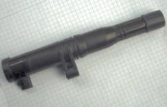
Some Ignition Coils ideal for use with this circuit have also been added to the science store.
Oops! Missed it off the list :). The diode used is just a 1n4007 or something similar. This diode is rated up to 1kV so it should be able to withstand any nasty spikes.
Dear Sir,
What kind of diode(part) is the D1 at the A DIY Power Pulse Controller ?
I am looking to use this circut to drive for paralel ignition coils.
Thanx