A DIY Homemade
Ignition Coil Driver Circuit – A High Voltage Power Supply
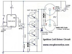
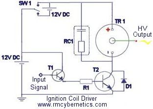
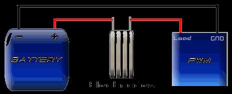
One of the simplest ways to make a battery powered High Voltage power supply is to use a common car ignition coil. Ignition coils are a type of induction transformer based on the Tesla Coil invented by Nikola Tesla in 1891. The voltage rise is not given by the turns ratio like in a standard transformer, but is proportional to the rate of change of current in the primary circuit. This means to get a high output voltage you must be able to stop the power flowing into the coil as quickly as possible. In old cars this was simply done mechanically. For use as a HV power supply this needs to happen rapidly over and over. To do this a spacial square wave power supply is uses which switches power on and off to the coil hundreds or thousands of times per second.
![]() WARNING: High Voltage is generated by this device!
WARNING: High Voltage is generated by this device!


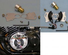
Standard ignition coils can be obtained from most car parts stores for around £25. It is not essential to use two 12V batteries like shown in the circuits shown below, but it will allow you to obtain bigger sparks. We have some compact induction coils available for sale for under £20. Click the link to check stock.
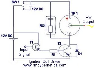
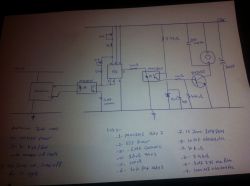
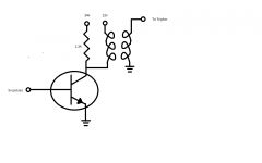
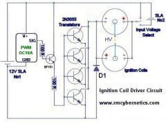
| TR1 | Ignition Coil |
| T1 | BFY51 Small Transistor |
| T2 | 2n3055 Power Transistors or HV MOSFET or IGBT |
| R1 | 100 Ohm Resistor |
| D1 |
1N4007 will do but preferably a Schottky Diode |
| RC1 | 0.1µF Capacitor + 10K Resistor |
This driver circuit is based on the commonly used 2n3055 transistor due to it high power switching capability. While these are cheap and high temperature tolerant, they are susceptible to voltage spikes caused by the inductive nature of the load (ignition coil). Pretty much any power transistor, IGBT or MOSFET can be used in this circuit as long as it is rated for at last 5A and 100V. Ones with higher voltage ratings will be less likely to be damaged by spikes. Further protection methods are outlined lower down this page and in the comments. If you use a MOSFET or IGBT instead of a bipolar transistor like the 2n3055, you should also add a pulldown resistor of about 10k between the base/gate pin and GND.
RC1 is used to help suppress high voltage spikes that can destroy the power transistors.
T2 represents two power transistors connected in parallel and mounted on a heatsink.
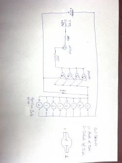
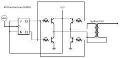
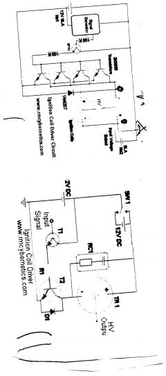
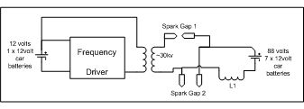
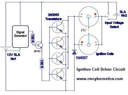 This next circuit is designed for a higher powered output. Two ignition Coils are connected in parallel but with opposite polarity. This means that the output voltages of each coil are out of phase or opposite to each other (when one is positive, the other is negative). Using this configuration the output is taken from the two coils output terminals, whereas the circuit above uses the output terminal and ground.
These circuits will work great for driving ignition coils for high voltage but they can be susceptible to damage from inductive spikes. When an ignition coil is being driven unloaded (open circuit on the output) there will be significantly increased back emf and risk of damaging the driver circuit. We sell an ignition coil driver module which has built in protection against most spikes that would damage a driver. It also includes an early warning indicator which will show you how severe the back emf is from your load.
Protecting Your Ignition Coil Driver
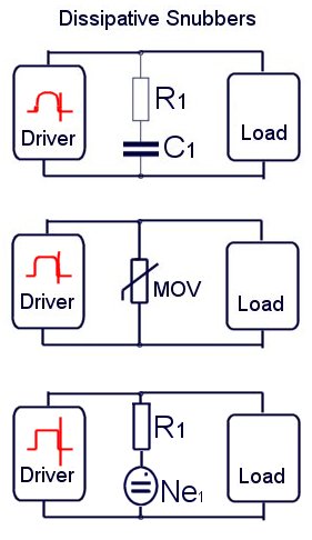 If you build an ignition coil driver to make high voltage sparks and arcs, you will need some sort of EMI protection for your circuit. Without it, it is very likely you will destroy the transistors or driver ICs.
Snubbers are a tricky subject, but in general they are used to reduce electromagnetic interference (EMI) or voltage spikes. There are many ways to reduce EMI and it can often be useful to use various snubbers in different parts of the circuit. These diagrams represent a few possible ways you can snub EMI in an ignition coil driver. These are known as dissipative snubbers because the excess energy is disspated as heat or light.
The top digram uses a series connected capacitor and resistor. The values used will depend on your drive frequency. (See RC1 at top of this page). Generally speaking, a bigger capacitance and smaller resistance will snub more, but also absorb more drive power thefore reducing efficiency. A compromise must be found that best suits your setup.
The next diagram uses a device known as a MOV (Metal Oxide Varistor). These are semiconductor devices which will only begin conducting when the voltage between its terminals exceeds its rated value. It will stop conducting when the voltage goes low again. In the example shown above, the MOV will short out any spikes coming from the load, but it is also shorting the driver circuits output for the same brief instant. The MOV chosen must be able to dissipate the power ans have a voltage rating that will cause it to activate before the voltage gets too high for the drive circuit.
You can also place a small neon indicator bulb (Ne1)in series with a 1k resistor and place this between the low voltage wires to your ignition coil. This bulb will begin to glow when the back EMF reaches about 100V or more. If you see it glowing, you need a better snubber like RC1 (top diagram) or a MOV (varistor) rated to clamp the voltage below the maximum your components will tolerate.


Hello
Is the PWM-OCXi v2.2 capable of driving two ignition coils at the same time? I would like to have one ignition coil output Positive and the other output Negative, but without the problems associated with the diy drivers above.
Thank you for your help.
Yes, Just connect the two coils inputs in parallel, but with one of them reversed.
Hello, Sir. I looked thouroughly the schem of HV Coil Driver with one coil. I want to use it for automotive ignition system. What is the frequency of switches of SW1 and where can I buy it. I’m an enthusiast. Will automotive TVS diods be able to save the circuits of ECU and driver. I mean 200 W diod 12V , Vt=13,3 Should they be installed in power line of 12V battery ? Or on the HV output also? Thanks in advance.
SW1 is just an on/off power switch which you can buy in our store. TVS diodes will help, though it is not a total solution. You need to filter the power input to the circuit so that noise does not get sent back to the ECU via the power lines. Filter design will depend on your operating conditions.
Hello!
Does anyone have a link to free software for making circuit drawings like the above illustrations of the ignition coil driver circuits? Mac preferred O.S,but windows ok >
Hello All!
I Am posting this here as a courtesy as the answer I got could benefit others too!
Greetings!
I Am working on an experimental Multi-wave oscillator. I want to use the setup you have listed here that employs 2 ignition coils.
https://www.rmcybernetics.com/science/diy-devices/diy-ignition-coil-driver
The HV output from each coil will be used to drive two MWO antennas simultaneously, one driven by each coil. So I want both ignition coils to be on at the same time. How do I modify the wiring diagram you have shown on that page to have both coils operational at the same time?
It is ingenious the way you allow the use of a signal generator to drive this circuit. One question I have on that is based on this. You show power connections for + and – to power the generator. Then you show ONE WIRE outputting from the generator to a 100R resistor.
The output leads from my signal generators all have a + and -.. In my research I do not always use the – lead and it is not connected to anything. In your diagram is this the + or – output lead from the generator being sent to the resistor? Also if I wanted to use both output leads from the generator to drive this circuit, how would I connect them?
Many thanks for your assistance!
God bless and be well!
ANSWER Hello,
Both coils are on at the same time, but the voltage will be of opposite polarity. If you want the same polarity, simply switch the ± connections around on one of the coils.
The signal generator must share a common ground with the circuit. The positive output goes to the transistor base pin, while the other connects to the circuit power supply ground.
Hello Again!
I also want to have spark gaps on both coils and a way to easily tune the coils to resonance. Re-tuning may be needed regularly depending on the test subject.
Also why are two sealed lead acid batteries placed in this circuit? I Am planning to use a high wattage PC computer power supply as the source to power both the coils and the Frequency generator.
A diagram rather than worded answer will help me understand best and avoid any HV OWCH mistakes.
Please advise…
God bless and be well!
The SLA batteries were used so it could be portable and to avoid using mains power. A PC PSU will also work.
I think these were done in Paintshop Pro, but there’s lots of online tools available now like his one.
https://www.circuit-diagram.org/editor/
What TVS would suit to protect this circuit??
Would your component number 1.5KE440CA 77V do the trick??
Polybus
Hello guys,
I’m facing EMI problem with 555 timer circuit when I connect it to Arduino as the LCD showing or behiave abnormal also resetting issue .
Iv changed the above design lil bit but I didn’t test it yet please have a look and let me know if you have any comments or idea .
Sorry for mt typos
not sure the correct image was uploaded, 2nd try
Hi!
Really love this site. I was wondering. I have a 80W CO2 laser which I’ve been powering using an old 10kV/23ma transformer (to mains via a Variac) and a full-wave doubler to power. 25kV ionizes the gas then I back it up to use it. (btw yes, I’ve got the experience from both school and professionally). I have heard and wondered about the possibility of powering it from a car batt using twoparallel HEIs and pulser. My electronics is pretty good but regulators and such were not my area and things have improved since then. Any circuit recommendations. I love your high current pulser and am planning on getting it…. along with other goodies.
Question 2: I have made tons of HV supplies but found that coming up with a low voltage high current supply (and also battery but it could be a car batt as well) has Frustrated me. 1.8VDC at 10.1 amps for an 8W near-IR diode laser.
I’ve seen some new regulators out there but am not sure how available they are and although I’d learn about them (and get better with the 555) I’d rather have someone who knows where their towel is give me a circuit I know is good.
here’s an image from an LM338 datasheet and I was thrilled to find it. I should talk to you about your custom work for either of these!
Our PWM-OCXi v2 is ideal for driving coils for high voltage.
Hi,
I want to build a high voltage Power supply With square wave (or cosine square wave) 15 kV 1kHz, 0,5mA output. I am going to Connect this to two electodes with a distance of 50 to 70mm to make a high electrical Field. My plan was to use a auto coil. Where can a finde a pulse modulator that can make good modulated square wave?
0.6W
What was the Wattage Rating on your resistors? Thanks
Hi everyone!
I have an MSD Blaster 2 car coil (50KV) and another normal car coil at home and i wanted to achieve the following conditions: 70KV, at 11 mA, and i believe high frequency.. its to try and replicate Herman Andersons project. He says he uses 7 cycles per second, does this mean hertz? i highly doubt it..
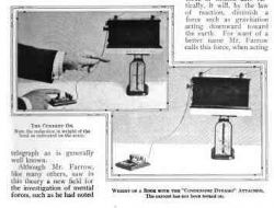
I am interested in reading about anyone’s experiences in reproducing Edward S. Farrow’s Gravity Reduction experiments circa 1911. The link is:
http://scripturalphysics.org/4v4a/ADVPROP.html#FarrowLinks
There are no descriptions of the internals of the device he used. The photographs give the impression of a Rhumkorff coil, probably with a "buzzer" type of interrupter. It was probably battery powered, and if so, would give an asymmetric waveform like that from an ignition coil. If so, reproducing the effect should be straight-forward. (Make careful note of the experimental setup; the polarity of the high tension tower on the ignition coil should be positive, but try negative too, as a Rhumkorff would have had both.)
If you have any thoughts or experiences on this topic, please share them.
It is to do with the first law of thermodynamics (conservation of energy), and the relationship between power, voltage, current, and, resistance (or impedance) as described in ohms law.
When the current switches off, the magnetic field around the coil will collapse. The energy in the field is transferred to the coil as an electric current flowing in the opposite direction to the initial current. Ignoring losses, the power (energy/time) in field will be equivalent to V x I. Since the transistor is now off the resistance of the circuit is very very large. Therefore in order to balance the equation V=IR, V must become very large and I very small.
hi! I have question in my mind which is in induction , that is, what are the factors that rise the output voltage of the coil to become grater than the voltage of the DC source supply when switching off the R-L circuit? thankyou
The efficiency of the coil does drop off as frequency increases due to losses in the core. Smaller coils usually work better at higher frequencies. The impedance of the coil will also increase with frequency. This means for the same input current at a high frequency, you would need to use a larger input voltage. After about 20kHz you will only get very low current on most ingition coils when using a 12V supply.
Gentlemen, You have an outstanding site! Keep up the fun and fantastic work. My question: during your work with the common ignition coil, have you identified an upper frequency limit where the operation and efficiency of the coil dropped off?
Thanks in advance.
R
You will need to use a much higher value of resistance, and use a several resistors to form a voltage divider to that it will suit your scope.. You should also discharge the spark to ground via the resistor so that your scope has a ground reference.
The spark will also discharge a lot of EMI, so you might want to shield it or at least keep it a reasonable distance away.
I have built the ignition coil driver circuit posted on your website(4th dec 2006) and I am getting a good spark with a spark plug. I am now trying to measure the current in the secondary circuit using a .24 ohm resistor(actually a piece of wire) in series with the spark plug and measuring the voltage drop across it. I continually get an overscale reading on my meter. Can you explain this and suggest an alternative way of measuring the secondary current.
Robert, you that you’ve built coil by scheme. I can’t get one thing. Sw1 need to be opened or closed? Or is it an activation key for HV coil to produce voltage? Thanks in advance
That transistor looks ok, but please consider my comment in post #4704
Hi, i’m trying to run a coil on plug system, the ecu that i will be using requires the use of ignitors to drive the coils, would this circuit be ok for this purpose and would BU508A transistors be a good replacement for the 2n3055
The power capacity is limited mainly by the chosen transistor. If you need more power than the one shown, simply choose a different transistor. There are some quite powerful IGBTs available these days.
Allthough this circuit works, it is really not good. Paralleling bipolar transistors in this way is not reliable. You can use MOSFETs or IGBTs in parallel and they will be much more effective.
As you are using an OCXI as your drive signal, you can simply connect the SIG output terminal connector to the gates of your array of parallel MOSFETs/IGBTs without the need for the BFY51 preamplifier. You will still need to protect the array from voltage transients though
I just realized that the TSV placements I depicted are way wrong, where not the least of which is the one in parallel with the switched common side of the coils.
So please disregard my previous posts and images, as I obviously do not have these circuit anywhere near ready for your review.
sincerely,
mac
The application of driving two ignition coils in anti-parallel is still most unique and of distinct interest, as I am also aware this is a very old article. However with references being made to a “modern alternative being available”, the PWM and PPC modules being referenced do not seem to have sufficient power capacity to drive two ignition coils, much less two HEI coils (outside of the OCXH which is tad above a hobbyist budget). If I have missed finding such an application or the relevant DIY project, please let me know.
Else, note the attached modified duel coil schematic with which my intention is to drive two anti-parallel HEI coils utilizing an OCXI PWM coupled to the recommended IGBTs. I would like to verify this design, along with whether the TSVs and load limiting resistors are appropriately sized and are placed correctly within the circuit for adequate back EMF suppression. In addition, should consideration be made for the current rating of the other two 100 ohm, and 2.2K ohm resistors; i.e. more than ¼ watt?
I would also like to commend the RMCybernetics sales and warehouse staff for their accurate filling and prompt delivery for each one of my on-line orders.
Thanks in advance,
Mac
This circuit is really not worth building. As I have stated before, this article is very old and there is a modern alternative available. See power pulse controller.
I just had a few questions about this. I redrew the schema to show what im going for. These values may not work. I chose the 2n6059 because it can carry more current than the 3055 and it should take less of them to do a larger job. The coils are still wired in anti-phase there are just 8 of them now.
1. Will this work?
2. How many amps will my power supply need to be (I want to be on the safe side)
3.Will the 2n3904 deliver enough voltage and current to fully switch on and off the 2n6059’s
Thanks for any help guys. This site is awesome.
The values needed for the snubber will depend on the operating frequency, the spec of the coil, and the load on the coil. You will need to detimine what works best for your setup. In the twin coil example you might also need a snubber. It was just left off the diagram for simplicity.
May I just say first off Great web site. My question is, is the snubber in your circuit below (I’ve just re-drawn it so I’ve got the pin outs on it) sufficient for this circuit as on another of your pages you recomend using a 100 ohm 50 watt resistor with a 330nF 1kv capacitor for general use. I’ve also noted that on your twin coil circuit that there’s no snubber. Am I right in thinking thats because they counteract each other.
Something like the power pulse controller would work well with an IGBT. We also have similar devices available in the shop.
Most older ign coils are around 1.0-1.3 ohms. the newer coils are 0.4-0.6 or so
Will this drive them using a IGBT. You said the circuit shown is the old circuit, where do i find the new one?
The OCBI is not complex. Ignition coils make a lot of voltage spikes so your circuit needs to deal with this otherwise it will just fail.
jerry – Friday, 6th May 2011 5:03am – #4559
I would like to drive a new automotive coil (coil on plug) I need to be able to drive 4 at one time. Coils are .4 to 1.1 ohms each. will this work….about 30 – 60 times a second.???..You responded i could use ocxi or ocbi..but I don’t need anything that complex. I would like to drive 1 coil with 4 drivers. I don’t need any adjustments to change p/w or anything once done. the coils will be in a clear plastic case to display the spark. could I somehow just make a simple circuit to drive them without the adjustments? I thought i saw boards that you sell for this, do you still have them?
You will certainly need to protect your circuit. Use an RC snubber at least, also a power resistor of a few ohms in series with the coil. You may also need zener diodes and schottky diodes on the power lines.
Hi
I have designed similar circuit using AVR microcontroller as a driver. I have few questions concerning these circuits:
1. After watching your website I have decided to change mosfet to IGBT transistor but the question is do I have to protect it by MOV or internal protection of IGBT would be enough to this application?
2. Do I need necessarily use optocoupler? I have two power sources (one for uC and one for coils) and I wonder can spikes from the ignition coils can do much harm to the uC if they go through common ground. Or asking the same question in different way – does common ground in this case is dangerous to the microcontroller?
I have posted my whole project with questions on
http://www.edaboard.com/thread227710.html#post970918
thanks in advance!
Great website
The output voltage proportional to the rate of change of current at the input. You can vary the fall time, or the pulse width of the drive signal to change the output voltage.
Hi,
How to regulate spark length (Strength) for your circute diagram of Ignition coil driver, i require, 0 to 20 KV. out put High voltage.Pl, guide.
Thanks
Thank you
The results you get will depend on how quickly your magnetic filed near the sensor is flipping. It would need to be about 50Hz or more.
I appologize, Iguess I was still confusing in the way I asked the earlier question. I was thinking of using a latching type of hall effect sensor where T-1 is shown in the circuit. The output of the sensor feeds 12v+and- to the gate of an ibgt to charge and then discharge the ignition coil. So would the circuit remain as shown with those changes, not considering the required 12v+ and 12v- going to the sensor?
You can replace both transistors with a single IGBT, but you will need at least 10V of signal to switch it well. You should also have a 10k resistor between gate and GND.
I guess I should have asked my previous question this way, How would this circuit differ using a hall effect sensor like the melexis us 1881 ua configuration and a ibgt transistor.
Thank you, D
What changes would be required to this circuit if a hall effect sensor and a igbt was used in place of T1 and T2?
You should use polypropylene or another quality capacitor good for power circuits.
Dear Sir, i also confused with RC1 capacitor value also. and what type of capacitor is this? metal, polystert? ceramic or what type? as size does matters in module. small parts small module also. thanks
The 2n4055 Would not be suitable for those coils. You would need to use an IGBT rated for more current. If you are driving four coils at once, you should use a separate transistor for each. If you want a ready made unit, Our Power Pulse Modulators will work well. You can easily link four of these together to do what you need. You can use the PWM-OCXI, or PWM-OCBI.
I would like to drive a new automotive coil (coil on plug) I need to be able to drive 4 at one time. Coils are .4 to 1.1 ohms each. will this work….about 30 – 60 times a second.??? Or hoe can I make this work? do you have something that will work…
Yes, in the diagrams there is a switch for selecting between 12V and 24V
Does this circuit works with 12V? i want to make this for motorcycle.
R1 should be 1 watt or more.
RC1 should be 10W, and 1kV. You can use a variety of values here. I often use a 1kV 220nF capacitor with a 50W 120R resistor. You may have to determine experimentally what values work best at the frequencies and duties you will use.
Hello, i was talking about R1 & RC1 [capacitor voltage? + resistor watt?] thanks
Which components are you asking about exactly?
I m in need of a circuit to replace point brake from my motorcycle( yamahard350) 2stroke. it has double cylinder and i want to use double TCI saperately. i have seen some in market but as i m from India and can not buy from outside India. you did not explain wattage or volts of your capecitor and resistors. it is quit difficult to find it without knowing volt and wattage for both. attaching an image also for showing the readymade TCi for RD . t hanks
This is actually quite an old article, I would recommend you use a modern transistor such as an IGBT. The IRGB4061DPBF would be suitable.
Hello, I have a question on your Ignition Coil Driver – A High Voltage Power Supply… You state that “T2 represents two power transistors connected in parallel and mounted on a heatsink.” So that means you must use two 2n3055 Power Transistors or one IRF740 MOSFET?
Thank you so much you have a great site!
Jack Hallaran Atlanta, USA
hi… in my last message I spoke about NAUDIN, SRSG M.M.C and NST (see the subject) With this heading, I think qu’ it T possible to carry out same the tests with two electrodes (stainless and stainless in l’ water and of sodium bicarbonate. the exit being able to be amplified by the part after flyback coming from a television set. this assembly will allow other expéiences. if you summers intersse by the production of fuel gases: gonin.jean@neuf.fr .merci
Cabral,
The input voltage for most ignition coils 12 – 16V. If they are blowing up, it is most likely due to over heating.
Jim,
I don’t know. Look up the part number on-line.
Noah Spurrier,
Yes you can use a TVS.
The driver must be square wave to work properly.
Would a Transient Voltage Suppression diode (TVS) be appropriate across the load (in place of RC1)? Could one also be used in place of D1?
Would a sine-wave oscillator instead of a square-wave give better efficiency for driving an ignition coil?
I have an ignition coil with 3 pins – i presume one of these is an internal ignitor, but i can’t get any output from the coil. Can you give me any information on how a COP with internal ignitor works? What sort of signal does the ignitor require?
Hello friend! First congratulations on your site!
I have some questions and hope you can help me:
Rode a circuit with a 555, but only with an astable common, not with PWM and am using a transformer 3A / 24V automotive and coil, but also do a lot of spark off the coil, still had some problems that just exploded ! I wonder:
How many volts can support an automotive coil?
What is the maximum frequency that it can support (I’m using 2kHz)
What would be the reason it blew up, since it does not is not too hot?
I appreciate the help! Hug from Brazil!
Cabral
I don’t understand what you are tying to describe by “sends high voltage from the negative side of the coil terminal to ground”
I have duplicated your 555 timer circuit including the snubber and all. I am using only one ignition coil. When the 555 timer drops the voltage to zero volts, the coil sends high voltage from the negative side of the coil terminal to ground. Any ideas why this is occurring? No spark is produced…
If you need a custom circuit made, please submit your information to the custom electronics page.
This is a terrific site. Many ignition coils now seem to be geared towards capacitor discharges, instead of transistor switching designs. Do you have any interest in developing a CD based ignition coil circuit?
Cheers!
You can’t do it with one transistor, h-bridge is what you need.
I would suggest not using the 2n3055 though. This is an old article and there are much better alternatives available now. You would be better off using a MOSFET or IGBT as you can get ones with a higher voltage rating than the meagre 100V of the 2n3055.
With most ignition coils the HV return is internally connected so you would have no choice, but if possible, you should use the common ground.
Be aware that ignition coils can make a lot of feedback so you should make sure your low voltage electronics are well protected.
Ok, so, it cant be done with a single transistor? When you say bride arrangement, I assume your meaning something like a motor “H-Bridge” driver. I set this circuit up in a circuit simulator, and it seemed to work ok, but it seems overly complex. Is this what you were talking about? Would it be better to ground the high voltage output to the ‘common’ ground? or the ground terminal of the coil? For simplicity, I left out most of the 5v circuitry, and the protection circuitry (is it even needed in this configuration?) for the 2n3055s.
You will need to use a bridge arrangement of transistors in order to use a bipolar square wave.
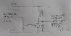
I built a circuit similar to these and have decided to take it a step further. I am looking to make the coil input “see” a square wave AC signal that pulses high at 12v and low at -12v. I modified my circuit to something similar to this image, but it doesn’t work for some reason, likely a simple problem I’m just overlooking.
The finished product will be connected to a 30kv TV tripler, to rectify the voltage, and obviously, triple it. So it needs to be an AC signal.
When turned on and fully connected (without the tripler), the 555 timing circuit doesn’t work, but when setup in a more classic way, it still does, and once this circuit is disconnected from the timing circuit, the timer starts pulsing again. All the components test good.
Do you have any suggestions of how to achieve what I want to do? Or can you see why my pictured circuit wont work?
The output spark length is proportional to the rate of change of current in the primary coil. This means more current, or fast transistors can improve performance.
I also did a circuit using a dimmer and a capacitor, and the sparks were good but it is unstable so I’m looking for something that functions more stable
Hi, I made a circuit using a 555 timer and a power trasnsitor a BU941 voltage of 12 volts using a bosch ignition coil of 36 kv i can get it to work but the spark they produce is too short as 7 mm
How could I do to increase the spark to more than 3 cm
tks
They would be tough enough, but they are very fast. Such a fast diode would prevent the ignition coil from working.
Hi, I notice that that you have some fast high current diodes FFPF30U60STU -would these be tough enough to act as freewheel diodes on the ignition coil?
[Perhaps stacked in some way?]
-I have had really nice arcs using the IRF740’s but I havent managed to get these to live for much more than a minute, yet 🙂
I don’t know. This is beyond the scope of this article.
But still, is it possible to control this circuit using a hall effect sensor instead of using the chansaws HV transformer?
Would you mind pointing me a schematic?
Use the “Search” link at the top of the page.
hello. How to find the page which makes it possible to be able to read the questions that j’ (jango) already posed .merci
Ignition coils need a DC pulse to fire a spark. I’m not sure the voltage from the alternator would change quickly enough to do that.
Hi
Is it possible for me to use this circuit as a replacement for an old ignition circuit from an old chainsaw 2 stroke engine? I was thinking of re-winding the high voltage transformer with very little windings so that i get a very small ammount of output voltage and then use that output as the input of this circuit, instead of using a signal generator, in fact the transformer would act as a signal generator.
Then i would connect the high voltage output from the sparkcoil from this circuit to the engine’s sparkplug.
The bad thing about this is that i need an external power source, as a battery, to run this ignition system, expecially because there’s no return current to the battery. Maybe i should had a dyno to charge the battery at the same time.
Hi
I have a Stihl 2 stroke chainsaw engine and i want to replace the entire ignition circuit as it is badly damaged. Is it possible for me to still use the flywheel mounted in the engine and the transformer in it too but re-winding the transformer so that i have the necessary output voltage to drive this circuit throught the -input signal-? Which at the same time, the output would be connected to the engine’s sparkplug.
Thanks!
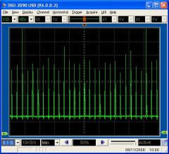
this is what i get at the power transistor’s collector’s terminal. is my snubber ok?if not, what waveform i should get?
this is what i get at the power transistor’s collector’s terminal. is my snubber ok?if not, what waveform i should get?
You need to protect the transistor from over voltage by using voltage clamping devices such as MOVs or Zener diodes. You could also use snubbers.
So, i have tried and failed. I made a flashy pcb with uart, analog inputs, lcd port, etc. and an IGBT transistor. (https://www1.elfa.se/data1/wwwroot/webroot/Z_DATA/07109796.pdf).
The attached image has the part of the schematic with the IGBT transistor and an 3d image of the complete board (the kicad-components i made have no 3d footprint). The reason for the “dual” gate connection to the IGBT is that i was not sure if the microcontroller was able to control the igbt, but in the end it was.
I was able to create a tiny arc (3 mm) by adjusting the frequency and duty cycle, and the diode (D1) got quite hot. I removed the diode with hope for a bigger arc, and that broke the igbt in one second. The power supply i used was an old pc psu with 12 amps from the 12v output.
So, before i buy another igbt for 15$, should i replace the diode with a cap and resistor, or should i use some different kind of transistor?
The coil would have quite a high impedance at 40kHz so you might need to increase the input voltage to get a good output.
Hi
This looks really interesting!
Recently i have seen some videos on youtube about plasma speakers http://www.youtube.com/watch?v=3AD-deOyljA&feature=channel.
My idea is to use an AVR microcontroller to generate the PWM signal at something like 70 kHz and sample sound with the a/d converter at something like 30-40 kHz. The sampled values would then be used to set the duty cycle of the PWM signal. Do you think this could work with an old car ignition coil to generate sound? It would be really cool.
If i manage to build this i will post the schematics and the source code in case someone is interested.
Thanks!
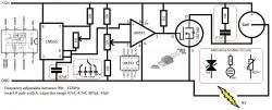
Yes, Just replace the capacitor C1 with one of a lower capacitance. It can simply be unplugged from the board and replaced without soldering. 220nF should give a range of about 3Hz to 600Hz.
I just tested the OC10A pwm on a fuel injector and it works great. I do have some back current I need to adjust with a varistor but so far nothing is heating up at all.
My question is what would be the best way to lower the frequency of the 1mohm pot? I would like to fire about once per second to perhaps 20 times per second. Is this feasible on this board?
If so what would you suggest?
Thanks,
Bing
Yes
hello. Then I to connect a FLYBACK in the same way a cell HH O Thank you
many thanks, Thats very helpful, I have seen Yuasa 4AH SLA batteries on ebay that should do the trick. I will be shopping with you on Thursday, either online or by phone if thats ok, there are some other parts I need that i couldnt find on your site. thanks again
Colin
Actually the Ah rating of the battery refers to its capacity rather than the possible output current. For example a 3.3Ah battery would last about 3.3 hours with 1A being drawn from it. Practically you would get less time than this as they do not discharge in a linear fashion. I would suggest a 3.3Ah SLA would be the smallest you could use without it running out annoyingly fast. A bigger battery wont improve performance but would last longer.
thanks for the answer
i have been looking at SLA batteries on eBay. Unless you sell these as well?
what sort of AH should I be looking at for reasonable result
sorry, just looked at the spec of your PPM, 10A
You can use a mains adaptor but it should be rated for about 4A or more. These can be a bit expensive.
You don’t need a car battery, you can buy smaller 12V batteries called SLA (Sealed Lead Acid) batteries.
hi, instead of using car batteries would it be possible to use a mains transformer to 12v DC and what output would be needed, using your PPM and one of your High Voltage Spark coil with a single 100mm Electrode plate.
the whole thing needs to be transportable by a single person to take it to Uni
Thank You
Colin Cade
That is a good question.
The reason is due to the way transistors work. The transistor is activated by applying a voltage or current (depending on the type of trnasistor) to the base (or gate) pin. The voltage is applied relative to the emitter (or source) pin.
For example;
Some transistor is rated to switch on when the voltage on the gate pin is 8V. This voltage is measured between the gate and the source pin. When the source (or emmitter) pin is grounded, then the voltage you apply to the gate pin is always relative to ground (0V). If the source pin is connected to the load (ignition coil), which is then connected to ground, then the source pin will be higher than 0V when the transistor is on. If you are only applying 8V to the gate pin (relative to ground) then it wont be enough to switch the transistor properly.
This is epecially problematic with coils becasue the voltage would oscillate and the circuit would be unstable.
I am curious, most of the designs I have found for driving ignition coils put the coil on the positive supply rail and the switching device in its path to ground. (Yours uses this arrangement as well) My own initial thought would have been to do the inverse, with the switching device on positive rail and coils common negative on the ground. (Isn’t it like this in a car anyways?) Is there any reason the former arrangement seems to be preferred? I would think it should work equally well in either orientation? (But admittedly I haven’t tested this)
luke,
You need to post a circuit diagram otherwise I can’t help you.
jango,
I don’t understand you.
Hello. In your “Page” HH O , a diagram shows how to connect the electrodes. Then to connect same manner a FLYBACK with a couple RC1. (Even with a low power of exit). thank you
Hello. I wanted to deliver my opinion to Paul Kilidjian@ciudad.com.ar The addresse e-mail was refused What is the error. Thank you
i have jest bought the maplin’s 555 Astable Switch Kit and i am trying to use it as a ignition coil driver but i have no ider how to wire it up plz help
Jango,
You control the current by adjusting the setting of the duty (pulse width).
A snubber (RC1) should just be placed in parallel with the load.
atuk,
A potentiometer would likely be destroyed if you put it on the HV output side. If you want to control the output current, you can just control the input current using Pulse Width Modulation.
The output current could be measured by placing an ammeter in series with the output, or by measuring the voltage drop across a small resistor and calculating it using ohms law.
hi, how if i want to contol and measure the arcing current? can i just put ammeter and variable resistor in the high voltage side of the ignition coil?
Hello. I wish to connect a ” flyback ” on is my HWM .is the diagram of connection it correct? The couple ” Is RC1 it correct? thanks
Hello. While observing, without knowledge in electronics diagram II, I think that to protect my PWM, I can include couple RC1 between the points ” A”. Is my idea it distorts?
hi RM.
i’m bulding a spark generator like andrew’s design. i need your advice, if i want to measure and control the arcing current,what should i do? is just putting some potentiometer and ammeter?
hello. with the diagram attached (for production HHO), then I to regulate l’ amperage Thank you
hello. I wish to make use of my PWM, like a generator which can provide me a going current of 0.2 mA to 5A.what connections must I use?. Thanhs
Hello., Thank you very much for your answer concerning the circuit with 4 transistors. I also wish to make l’ electrodeposition (plating)(CU). Which are the terminals to be used. Then I to regulate l’ amperage of 0.2 mA to 5 A. Thank . With your good answers, I
ordered a PWM
Close. The best way would be to use the SIG connector on the PWM circuit.
C du BFY51
2 B E
+ batterie B collecteurs 4 2055
Emetteurs 4 2055
– batterie
Helo. I want to connect a PWM to the circuit with 4 transistors and 2 ignition coil.en l’ without knowledge in electronics, I studied the diagrams for HHO, the gun, the first diagram of this page. I found a solution! ! shown in my message. I connect L+ connection to resistance (100 r) of the BFY. Thank you to say to me if my idea is good. So not which is the correction. All my thanks. I think my schéma is bad .
Thanks I was afraid of that. Spark Gap 2 really represents two electrode plates. It is a special type of Plasma generator we are setting up in our lab. We know we need to have both HV and 88 volts DC on either side of the electrodes to get the desired effects. We’ll try placing a HV Diode where L1 is. If you think of anything I’d appreciate your thoughts. Thanks again.
hello. a good diagram is better than text, made me the diagram of the branchpoints of the PWM and connections on the circuit with 4 transistors and 2 ignitions coils. For me that is more precise Thanks
Yes, they will be restocked soon.
hello. our stock of PWM is close to zero.going to restock or offer an equivalent and compatible model.
One of the terminals for the PWM circuit is common with the PSU. This means that if you put power into the circuit (V+, 0v), you connect the load to the output (L+, L-) where L+ and V+ are allreday connected to the same place.
Hello. I received an answer to my last message. Large mercy. A message s’ is lost. I repeats it. All my excuses if that is doubled bloom. in the diagram presented in top of the page, with two ignition coils and 4 transistors, the generator presents only 3 exits. Which is the connection with a PWM which requires one + – battery and v+, v. Thank you for your answer. Cordially. PS Your site is a mine of information a little hidden
ello I wish to connect your PWM on the diagram with 2 ” ignition coils (see DER strom 2614). On the diagram, I see only three exits for the generator. Which are the points V+, V, it + and it – battery. Thank you
You will need a lot of inductance to block the 250Hz. What are you trying to achive?
I have a spark gap (spark gap 2) that requires both a ~30kv HV at about 250hz combined with a constant ~85volt DC. The 2 DC source grounds are not connected. I’ve used your driver circuit, it works great. When I hook up the 88volt supply I completely loose my HV. Have isolated the secondary of the HV coil with spark gap 1. When I hook the 85volt DC across Spark Gap 2, I still get the HV at spark gap 1 but no HV at spark gap 2. I presume that’s because the resistance of the 85volt batteries is less than that across spark gap 2 and thus appears as a short. I’ve tried to introduce some reactance with L1 but haven’t had much luck. Is there a better way to do this?
Simply connect the termianls. Gate to gate, source to source, drain to drain.
how can i parallel 2 Mosfet?
There are too many posibilities. Just check your connections are correct and the components are functional.
i found and read up on the opto-isolator, and i get how to use it now, so i’ll do that.
what do you think might be wrong? where should i start looking? any suggestions or ideas?
thanks:)
Waseem Chehab,
You would need to use an opto-isolator and make sure the input and output are not connected to the same power supply.
No it is not designed to only spark when you switch the power. You have a problem in your circuit.
Aldrin,
Yes, but the output will be DC and of lower current.
Der strom,
It is not likely to help unless you just make brief pulses at a very low frequency. The flash circuit steps up the voltage, and will release it as a pulse of current. If you are drawing power continually from it, it will just be wasting energy as heat in the electronics.
I designed this ignition coil driver circuit based on something I saw on the web a long while ago. It uses the flash circuitry from a disposable camera to charge a capacitor (the original flash capacitor). Then, the 555 timer circuit turns on and off a high-power MOSFET several thousand times a second, connecting the 300 volts from the camera circuit to the ignition coil. I was wondering if this would be a safe circuit to try, or if it can destroy the MOSFET and/or the ignition coil. Any help and suggestions would be greatly appreciated!!!
Sincerely,
Der Strom
Thank you, i ask another question.. can i use voltage multiplier in this circuit? to maximize the output?
i build this and it works great but im having a small problem now… im not sure if its what the circuit is designed to do or not but the only way i can get a spark is if i turn the power on and off, is there a way i can make it keep sparking when its on? or did i build it wrong.
btw great page this is my 3rd driver i try building, the first one was a 555 n it worked on a speaker as a nice signal gen, but never worked on a coil, the second was another type of 555 but just flat out didn’t work. i like this one cuz its nice and simple, i just used part of my first driver on the input signal, and bam worked :), thanks for the page
yeah i was thinking of some isolation, can you please elaborate on that idea?
Yes, but you should optically isolate your PC from your circuit
can i use the program audacity for the input signal and generate the square waves?
Yes. You should also add a 10k resistor between the gate pin and ground.
hello Mr. RMC, can i substitute the value of 2n3055 to IRF840 Mosfet? and how? thank in advance
Vaughano,
It is possible that it is ‘freewheeling’ too much current. What diode do you use? The RC will only help if it is over voltage which kills your diodes.
Richard Jones,
The connection you describe may give you odd reading because of protective components or reversed diodes in the circuits. Just measure between the coils input pins.
Thanks for the reply. I had the scope connected between 0V and the coil negetive terminal. Assuming that the primary coil would act as a pull up resistor, I expected to see OV while the ignition module (car) or IRF740 (my coil driver circuit) is closed, and 12V when it is open.
I also have your resistor and capacitor snubber circuit in parallel with the coil in my DIY driver to try to prevent damage to the MOSFET. I’m wondering whether this is affecting the oscilloscope trace? I think I’ll try disconnecting them to see if I can get a trace without for comparison.
Also, I had a thought which may be useful for your high voltage experimantal circuits. As well as using car ignition coils, why not use a car ignition driver module too? Most mid 80’s to mid 90’d VW’s, and many other cars have the ignition driver module as a seperate unit inder the bonnet. Typically they have half as many coil drivers inside as the number of engine cylinders from cars with an even number of cylinders (wasted spark ignition, and are driven by a 12V square wave from the ECU. You can’t dismantle them to see what is inside, as they tend to be bespoke chips, but they obviously have all the necessary transient suppression built in, and can be bought for next to nothing from scrap yards or eBay.
Hi, just a quick one… I keep blowing the D1 diode every once in a while, luckily i have a large supply of them. What would be the solution to protecting this diode? I dont think the RC1 arrangement would be protecting this would it? I see in Andrew’s circuit (comment 563) that he has a capacitor in parallel, would this be a solution? What values would be appropriate? (Im using two ignition coils wired in anti-parallel, running off 6 2n3055’s, otherwise everything is as above)… Cheers
I found the problem and I have fixed it. My driver works very well. Thank you for your help!
Maximising the duty would not neccesarily be advantagous as is could saturate the magnetic core, and just waste energy. It is doubtfult that it would be near 100% for efficient operation.
Where are you connecting your scope?
Hi, I’ve built a coil driver based on your IRF740 MOSFET circuit. It’s actually to simulate the primary side of a car ignition system, so I don’t have any big spark gaps or anything like that. The gap is provided by a standard spark plug. The circuit works fine – thanks for the info.
I have traces of real car primary signals from my oscilloscope (a cheap PC based DSO), which I have compared to the trace I get from my driver circuit, and they are quite different.
There is no noticeable 0V part to the 12V square wave which I am assuming is driving the coils in the car circuit. It looks more like a continuous 12V signal with the expacted back emf spikes of around 300V. I assume it’s beneficial in a car maximise the duty cycle of the wave, as the coil takes time to charge, but discharges almost instantly, and that the OV section must be there (otherwise there would be no spark), and that my oscilloscope is too slow to catch it. This seems odd though as it catches the back emf spike well. Do you think this is a reasonable explanation, or is there something happening that I am missing?
Sorry if the question is slightly off topic, but you seem to know far more about how to drive car ignition coils than anyone else I have found. Thanks,
Max,
Anwers to both yor question are on this page allready.
ScotchTapeLord,
It sems as if there is some problem with the 555 output. Possibly it is not at a good frequency for your coil, or the duty could be wrong. Also it could be that for some reason the 555 does not swith off quickly enough. Are you aple to observe its output on a scope?
Typically a MOSFET needs about 10V to switch fully on, make sure yur 555 is outputting enough voltage.
I am now using IRF740 (after turning my 730’s into low value resistors)…
I have the gate grounded with 10K ohms, and when I remove gate voltage the ignition coil sparks. However, when I put the pulsed output from the 555 to the gate, I still get next to nothing on the output. I’m using a very low frequency, and I have tried feeding the gate directly from the 555’s output, with and without resistance, and I have also tried a small transistor to amplify the pulse, which shouldn’t be necessary with a MOSFET… but I don’t know what else to do. My setup is like the first image on this page, using a basic 555-timer astable multivibrator.
The MOSFET works, and the pulsed output of the 555 makes an LED flash, so I am really confused as to why this is not working. I’ve tried replacing the 555 chip, and I get the same result.
What is other type of transistor other than BFY51 that i can replace? another thing is, what for ‘input signal’ at base of BFY51
I’m not sure of your 555 setup, but it can be used to sink some current. It is still usually neccesary to have a pull down resistor on the gate.
A simple test of your mosfet part of the circuit is to tap quickly the gate pin on a 12V source. This should make the ignition coil spark as you release the connection.
The MOSFET works when the gate is grounded (testing it with just a battery, not the circuit). Why doesn’t the 555 sink the gate current when it drops to Low?
I’ll get a few potentiometers and ditch the diode to figure out what’s wrong… I put 10K ohms of resistance between the gate and collector and got rid of the diode and saw no improvement.
If current is passing when you have no applied gate voltage you could try adding a 10k resistor from the gate to ground to make sure it is off.
Also maybe the diode is not great. if it is too fast, it would stop the dI/dt being fast enough for a HV output.
I’m now sure the problem is the MOSFET. I replaced it but had the same result. I even tested an unused one and saw it was passing an amp at 12 volts from emitter to collector with no gate voltage. Are all my MOSFETs defective? This would explain the lack of current drop.
Hello,
I’m controlling the gate to my IRF740 directly with 555 pulsed output, and have my coil between the collector and ground, but I can’t get over 400V (I charged a capacitor with it and tested that). I have a small capacitor across the coil inputs and a fast-switching diode antiparallel with the collector and emitter of the MOSFET. I’m guessing dI/dt isn’t enough, do I have to sink current from the IRF’s gate or something?
Type your message here message pour ANDREW
avec le schéma présenté en décembre 2006
quelle tension ( en kilo volts ) obtenez vous
remerciements
Electronic translation of gonin’s post:
*** with the diagram of ” DER STROM ” ” which is the ” ” hight voltage ” ” obtained *** for this diagram can one use your module PWM OC10A *** which is the power suplémetaire (in Kv) brought by a second ” ignition coil ” if I am not on the good bond, (my English has lacks) to indicate to me the good thank you and better greetings.
I translated your post using this page
In future please use this to traslate your mesages.
The translaton is not great so i am not exacly sure what you are asking. You mention a diagram by dr strom, what is the post number of this diagram?
Type your message here bonjour
*** avec le schéma de ” DER STROM “”
quel est le “” hight voltage “” obtenu
*** pour ce schéma peut on utiliser votre module PWM OC10A
*** quelle est la puissance suplémetaire ( en kv) apportée par un deuxième “ignition coil “
si je ne suis pas sur le bon lien ,
(mon anglais a des manques )
indiquer moi le bon
merci et meilleures salutations
The transistors wont determine the current flowing in your circuit. Assuming that your power supply is capable of supplying more than 4A, the final current flow would be determined by the impedance of your motor.
i wanted to drive a dc motor of 12volt and of 4 amperes so will a darlington pair of bfy51 and 2n3055 will be able to give 4 amps of current frm 12v input supply?
GONIN,
English only please.
rahul,
What motor? Use a fuse or a resistor to limit current flow.
wat kind of diode should i use to protect the motor frm current of 4 amps?
do the darlington pair of bfy51 and 2n3055 at 12 vdc input can generate current of 3.5 amps?
Type your message here
quel est le schéma de branchement d’un
POWER PULSE MODERATOR PWM-0C10A
avec une bobine de voiture
quel voltage puis je obtenir
10.000v 50.000v
merci et meilleures salutations
JackN,
No, just use a different transistor such as a MOSFET or IGBT. IRF740 is a good example.
richie,
Yes, this pulse width modulator would work great for that.
hi
i have several aftermarket ignition coils for motorcycle. i want to test which one works gives longer and bigger spark. meaning i want to know which aftermarket coil works best.
do you have a circuit that will provide spark for the ignition coil so that i can determine which one works best?
I was wondering if it would be useful to also Series connect a couple 2N3055 (E of 1 to C of 2 – Isolated from the other collector connections) with the Bases tied, for more voltage protection?
Would it be worth the trouble to guard against back spikes dividing the Voltage by 2 in series like that?
Then Parallel a few series sets for more Current support?
Would there be any problem of noticable propagation of the switching between them that would ruin performance of the spark signal (In other words: If the two transistors don’t exactly switch on at the same time)?
I don’t know how unsafe it would be. I can only suggest you don’t try it.
I actually have three of them, and if I connect them in series, I would get a total capacitance of about 833uF (sorry, it was 2500uF, not 2200uF). If I run it in very short “bursts,” do you think it might be safe? (Obviously, nothing at these voltages and currents are really “safe,” but I mean “not extremely dangerous/deadly).
Thanks again!!
Der Strom
The capacitor is used to limit the current into the ignition coil. More current = hotter spark. A larger capacitor will allow more AC current to pass through it.
I would think what you suggest is not safe. The capacitor and the ignition coil are probably not designed for so much current and could heat up and explode.
A while ago, I built an ignition coil driver like this one, but it used a .5uF, 250 volt capacitor. It seemed to work pretty well, except the output was not very hot. I was wondering if it would work (and/or even be safe to) put in a 2200uF, 300 volt capacitor instead of the smaller one? I imagine the output would be much, much more powerful, and I was wondering if it would even be safe. I read on a website somewhere that someone used a 24uF capacitor, and that output was very powerful. Any help on this would be greatly appreciated.
Thanks!!
-Der Strom
I have some links saved somewhere form when I designed an air cored inductor for something else, for which I also bought an inductance meter. Making an iron cored inductor for this application hadn’t occurred to me for some reason. I’ll look in to it. Thanks for your help.
How about a DIY inductor made from thick wire wound on an iron core?
Hi,
I am looking to build a very small circuit to allow aftermarket rev counters to read a 12V square wave – effectively a miniture replica of the driver and primary side of an ignition circuit. Such rev counters have a filter circuit on their input to stop the back EFM spike from the ‘-‘ terminal of the ignition coil damaging the circuitry. This circuit also prevents them working from a 12V square wave. My plan was to drive a small inductor (about 5mH?) from the 12V square wave via a transistor driver. Hopefully it’s ‘-‘ terminal will have a big enough back EMF spike to drive the rev counter. I have run in to a problem with the very low coil resistances of small inductors. They will burn out if connected across 12V. If you know of any simple way around this it would be very useful. Thankyou.
It depends how many 2n3055’s you are using. The BFY51 is used if your signal source is something like a 555 IC. Such an IC can’t deliver much current and could be damaged by driving the big transistors directly.
I could not get your second circuit to work when using the BYF51 transistor but as soon as I removed it from the circuit the 2n3055’s started switching properly, is the BYF51 really necessary or can I leave it out?
Thanks again for all your help
Could I use a LM358 for anything
Sorry this is beyond the scope of this article. This page is about driving individual ignition coils which is not related to the ignition systems of cars.
hello..
i’d like to ask your opinion regarding my final year project. i’m implementing voice recognition in car security system..so,if possible could you provide me the appropriate car ignition circuit..my project accepts voice command as input and processed by PIC microcontroller. the output from the microcontroller will be directed to car ignition circuit for activation..i’m just building the prototype,not the real one..many thanks..
I built one of these with a 555 with a nice big t4 heat sink, when i hooked it to my coil i can just hear the coil humming, and the pitch changing as i change the frequency on my knobs. i have the coil hooked to a spark plug, maybe im not hooking the spark plug correctly? i have the coil HV to the spark plug head then the body of the spark plug hooked to the – terminal on the battery… or could it be coil polarity?
Yes, The Schottky is used as it will respond quickly to and reverse voltage spikes and prevent the 2n3055 from being destroyed, but that can also have a negative effect on the output becasue of it preventing the current from being switched off quickly.
For an electric fence you will be using very low frequency and low duty with a mostly unloaded output. This will give you quite large spikes after each output pulse. A 1n4007 would help, but I would reccomend using a different transistor. A MOSFET like the IRF740 would work well as it can tollerate 4x the voltage of the 2n3055. A MOV rated just below the 400V rating of the MOSFET should be placed in parallel with the diode. If you are using a single supply for the whole circuit, you should also place a MOV rated to keep your PSU voltage low (a 10VAC MOV will be good for a 12VDC supply) between your V+ and Ground to prevent your ICs’ from being fried by voltage spikes on the power rails.
The Driver you have in the very first schematic on the page uses a Schottky diode across the 3055 transistor(s). This is an expensive item, especially if two are needed. However, in a later schematic posted by Andrew the diode across the 3055 is a 1N4007. I’m building an electric fence type circuit powered by the coil and my cycle time is more like 1 cycle per second. I’m using a 555 chip to drive the 3055 via a small signal NPN. Do you think the circuit using the 1N4007/MOV variant in place of the Schottky to drive the coil will work in this application?
You thought right.
i thought that the coil pack increased the voltage but lowered the amperage. ex +v -A. Am i wrong.
The amount of mobile charge carriers (electrons) in the coil does not change so no charge builds in the coil. When the voltage is applied to the input of the coil (an inductor the current flow begins to increase. When this flow of current is halted the magnetic field which was sustained by that current will collapse. A changing (or collapsing) magnetic field will induce a current in any conductors within this field. If the secondary coil is open at this time a large current can’t flow so the voltage will rise very high so that the overall energy is the same as what was put in.
P = V x I
If I is small because the only current is tiny from ionising the air, V must be high to keep P out equal to P in.
If your input voltage/current is within the ratings of the coil it will be fine, but if you exceed these it is possible that the insulation will breakdown just like the air does.
Another question or two, if you don’t mind.
Once a charge is built up in a coil and the primary circuit is switched off, what happens to the charge in the secondary winding if there is no path for it to discharge to?
Is the charge ever able to bridge the insulation within the coil to the primary winding to discharge, assuming a sound, unbroken insulation between the windings?
Thanx, yet again. I have learned much from your answers.
This whole line of questions stemmed from this Thread on a Motorcycle Forum I belong to. http://www.nakedgoldwings.com/forum/viewtopic.php?t=11577&sid=ff6c575c05a2220e6433123f1a7eb150
Should you have the patience to look at it, I would be interested in your comments on the veracity of some of the information offered. I am Briang on that site, btw.
Richard,
Both. The spark structure may vary slightly, but ionization will occur on both poles causing a spark to grow from each. When the two sides meet, a conductive channel of air will exist between the electrode allowing more current to flow. This is when you hear the typical ‘snap’ sound of the spark because the higher current flow super-heats the air causing it to expand rapidly and create pressure (sound) waves.
Alex,
No it wont output a square wave. If you want minimum current from it, you will need to limit the current using a resistor on the output. 5V is not really enough to get a good output from an ignition coil.
Hello. Is it possible to send high frequency square waves to an ignition coil and have it still transmit square waves or will it distort them. Also what is the best way to protect the PWM from the surge and still have it transmit those waves to the ign coil? am hoping for 10,000+ volts (the higher range I can get the better) and running off a PWM that puts out 5V. I want minimum amps coming from the coil. Thanks.
Just as a follow up, from which charged end, positive or negative (+ve or -ve), would the spark originate from the centre electrode of a spark plug?
Ok, that’s what my other tests have also pointed to. Thanks for your time!
I can only guess that the transistor that switches the current to that coil is damaged. I don’t know about cars, but I think it may be called the electronic ignition module.
Hello, I hope you don’t mind me asking a somewhat related question..no one seems to have an answer for this one. And I’ll also state upfront that I know very little about electronics so please go easy on me and use small words. 🙂
I’m trying to fix a 1999 Chrysler Intrepid (2.7L V6) that my grandfather owns. We’re getting a misfire on cylinder #4 (verified by fault codes and other testing). This is a Coil On Plug engine, no plug wires. We tried switching coils but the misfire stays at #4. Also tried new spark plugs. No change.
I checked continuity in the coil driver wire from the #4 cylinder coil connector to the PCM and there is continuity with no resistance. So the coil driver wire seems to be fine.
With the engine running, I am getting a reading of 13.4/13.5 volts on every coil connector (by disconnecting one connector at a time and probing the power feed wire). Here’s the interesting part. When I probed the coil driver wire in the same way, I get a reading of -0.06 volts at all the good, proper firing cylinders. On #4 where I’m getting the misfire, I’m reading (+)0.03 volts. And it’s a constant reading on all of them, it doesn’t fluctuate (as least not on the multimeter display).
Any idea what that means or why the “good” readings are negative voltage (reverse polarity?)? I’m not sure what the specs should be or if I should even being reading the coil driver wire with a voltmeter (multimeter).
Any ideas or explanations would be really appreciated, you guys definitely seem to know what you’re talking about.
Thanks!
Thanx for answering my questions. it has been most helpful.
When the voltage is sufficiently high the air ionizes and becomes conductive. The energy then passes to the ground. The grounded part of the spark plugs is common with the circuit which completes the return path for current. A return path is not always necesary and becomes partiularly apparent with high voltages. Any conductive body can act as a sink or source for electrical energy by having some electrons removed or added. This would often charge an object but it may not remain charged as electrons will leak off or back onto the object from the surroundings, therefore allowing it to absorb energy from the HV source again.
By conventional circuit I mean the need for a power supply to be connected to a load and the load needing to return to the power supply. Interrupt this circuit (ie with a switch or simply disconnect a wire)and the current stops flowing.
This, of course, is what is happening, generally, with the primary winding in a coil. Once the current stops the field collapses and the energy built up within the secondary windings has to go somewhere. But what has me confused is that this energy can flow without the apparent need for a return path, as in a circuit.
Yes they fire independantly. I dont know what you mean about needing a conventional circuit.
Thanx for answering one of my questions re Wasted Spark Ignition systems. Am I to understand, then, that it is not required that either end be actually needed for the opposite end to fire? That is to say that the common practise for a mechanic to pull off a spark plug cap while an engine is running, in order to test if a particular spark plug is firing is not causing the opposite spark plug to stop firing as well. Therefore, would you say that the need for a conventional “circuit” is not required when dealing with such high voltage devices?
The voltage at any instant is a measure of a potential difference between two points. If the difference between the common ground (0V) is large enough, a spark will form. Being +ve or -ve does not matter it is the difference between the two electrodes that matters.
I am interested in how a Wasted Spark Ignition System functions. In such a thing the spark plugs are connected at each end of the secondary winding and both plugs fire somewhat simultaneously. Apparently there is no reference to ground from within the coil to the secondary winding. Essentially both plugs and the secondary winding is in series.
My question is, what is the science behind the ability for both the positive end and the negative end to spark to the same ground reference? I would also ask how it is possible for either plug to continue to fire if the other end is actually disconnected from its respective spark plug?
Hey RMCybernetics, I just wanted to drop in and say thanks for the great schematics and invaluable help! I’ve finished and it works great!
Ignition coils produe an output proportional to the rate of change of current. LC resonating them will not work well.
There will be several resonant modes of a coil. At several frequencies, you will see a distinct rise in output voltage.
I was thinking about making some kind of dual resonant tesla coil (drsstc) from an ignition coil. What do you think? 2 hv capacitors paralleled with each coil,to make from them LC (and 1 capacitor is variable). Then tune them to resonance.(or near-resonant frequency) And then drive it with wave,which has same frequency. How about that? If i’ll find way to measure inductance of each coil,i’ll definetly try to realise this idea.
—-
And what will be,when you drive your coil with resonant frequency? (i have kV meter (it shows 20kV max) ) Voltage will suddenly rise up?
The impedance of the coil increases with frequency. This means the higher the frequency the lower the current flowing in the coil. Also the driver circuit will produce less square pulses as the frequency increases, The pulses must be as square as possible.
I was able to get the circuit to make an arc using an ignition coil, but it only works when the frequency is below 1.5kHz. Above that the arc dies, but I can still the coil humming. Do you have any ideas why that is happening? I want to drive the coil at around 45kHz.
The expansion of the gas will be related to its temperature. You will need a large capacitor, the larger the better.
Would this be the sort of capacitor used in flashtube or would something smaller be enough?
I was hoping it could be excited somewhat close to how lasers or flourescent bulbs are excited.
The voltage is plenty but the current of the coil alone would not be. It would be neccesary to charge a capacitor and discharge it as a large current pulse to cause rapid expansion of the gas.
I am seeking to do a project wherein high voltage electricity is used to excite carbon dioxide gas so as to cause the CO2’s pressure to be increased thereby exerting a force that can do work. And I am wondering if an ignition coil high voltage power supply would be able to deliver enough high voltage and current to excite about 3 ounces of CO2 gas to a pressure of 50-60 psi.
i’ve scrolled this site and i found out that some people make little mistake.
– a 2N3055 is not advisable for an ignition coil due to kick-back voltages (30-3000V) and as you know a 2N3055 can only withstand 50-60V (i think).
i would advise an 2N3773 those can handle 100-160V i think
-also placing a diode over the collector-emitter isn’t that goed if you want high voltage peaks
of course it will protect the transistor, but it will filter away that high voltage peak.
– The best method for building an ignition coil driver is
(and im talking out of experience)
a 555-signal driver powerd by a battery or some other low voltage source (note that the voltage must be at least 5V)its also advisable to use a darlington transistor to magnify the signal coming out of the 555.
then as switching transistor a 2N3773 or a robbust MOSFET that can handle some voltage. and over the Transistor/MOSFET, you place an 100V VDR this should protect it from kickback
and at last not least,the current trough the coil. an voltage from 12V to 80V should be enough and a current of maximum 6A or else the oil in the coil wil boil and eventuelly the coil will explode under the pressure.
i find it important to give this information to you becouse ive seen a lot of accidents with those things.
i hoped you learnt from it 😀
The output is biased AC with a waveform mile this. An inductor reacts against a change in the flow of current. When the square wave goes from off to on, it takes some time for the current to begin flowing fully. When it is switched off again it takes some time for the current to stop flowing, but when the transistor goes off it forces the current to stop very quickly which causes a high voltage spike.
When the coils are wired in opposition they both output pulses of opposite polarity. So if one outputs +20kV, the other outputs -20kV at the same time. The difference between these voltages is 40kV.
I was under the impression that the square wave signal (pulsed DC) caused a magnetic field in the inductor, when the square wave is at zero, this field and creates a high voltage DC spike.
You have mentioned that he coils are orientated so that when one is fully positive, the other is fully negative so there is a larger voltage between the two, this however would involve the output of the coils to be AC.
I’m a bit new to all this, so i’m sure most of what is written herein is wrong, but if does generate am AC output could you please explain how?
Thanks
Yes you can place it there to absorb high voltage spikes.
Where do you need to put the MOV? is it between the +ve and -ve of the two coils? (on the same track as the diode but in between the low voltage terminals of the coils???)
All help appreciated, great project.
I’m wanting to test out this circuit with the most appropriate IGNITION COIL possible and am wondering whether I should use one built for Inductive-Discharge or Capacitive-Discharge. Any advice?
p.s. this circuit is untested and dangerous!!!
khobby@gmail.com
Guys I need help….Where do I get a circuit board for this proyect…..
Well im still learning on the induction heating side, but i can answer the mechanic question about driving with a shot ignition coil, and my experience says that if have a shot ignition coil you arn’t driving anywhere. and if its just starting to wear i would imagine it wouldnt hurt the engine, just merely not allow it to operate at its full potential. FYI the ignition coil is the part that is actually turned on and off when you turn to key on (in relation to the engine) and its main job is to multiply the engergy from the 12 volt battery system so it can send a really hot spark to jump the gap on the spark plug thus igniting the air/fuel ratio. if you trying to find one on a junk car, find the spark plug wires (if 4 cylinder there will be four wires running to the side of the engine, 6 cylinder there will be 6, so on with 8 or even 1 for that matter) anyway the opposite end of those spark plug wires go into whats called the distrubutor cap. there should be the number of cylinders the car has going into the cap plus one more (this wire is what carries the mulitplied voltage to the distributor to be distributed. follow that wire and grab that S.O.B!
Haha, You should ask a car mechanic, I don’t know.
Is it safe to drive a car if an ignition coil is shot or will that cause more damage?
Tracker,
A plasma globe needs to be AC. The difficulty in what you want to create is the variability of it. It would be relatively simple to make a circuit which oscillates at a fixed frequency anywhere in that range, but being able to adjust from DC to 5MHz with one HV device would be very tricky and expensive.
Dan,
The capacitor would need to be charged to a higher voltage than the supply for it to give you a better arc.
All i was thinking was that the 2nd circuit could be triggered so the capacitor discharges through the coil; creating a higher powered arc.
thanks!
Hello
Thanks for the reply, what I want to do is to drive a plasma globe at frequencies up to 5 meg so I sumize I would not need the DC side of this etc, is that perhaps something you could organise with your services.
Dan,
No, not really. What exactly do you want to do?
Tracker,
No. The reactance produced in the coils of the transformer will impede the flow of current more as the frequency increases.
In order to cause significant current flow in the coil at this frequency, the input voltage would need to be much higher. This would need a whole different setup.
hello
When using these various circuits to generate a high frequency spark. Would the circuit be cabable of operating in the mHz range typical 0 -5 mHz and if not what would limit this factor.
Thanks
RMCybernetics, thanks for taking time to do this for everyone. is there any way to ‘splice’ your circuit
https://www.rmcybernetics.com/projects/DIY_Devices/homemade_signal_generator2.htm
with this:
http://www.velleman.be/downloads/0/illustrated/illustrated_assembly_manual_k2543.pdf
to create a more powerful (capacitor discharge) pulse?
It could be anything! I’m not psychic. If you built exactly what is shown on the site, connect it to a suitable power supply and coil, it will work as described.
I tried your circuit with an ignition coil, but it doesn’t work. Do you have any ideas of why not?
The resistor is used to limit the current drawn from the signal generator. Without it the signal generators output IC (a 555 timer) would likley heat up and burn out. Without the resisor the circuit will still work for a while until it overheats.
What would happen if there wasn’t a 100 ohm resistor after the signal generator in your circuit? Is it there to protect the signal generator, or does it increase performance?
I got my signal generator working, but it doesn’t work very well on my igniton coil. I forgot to add a 100 ohm resistor on the output of the 555 timer, so is that my problem?
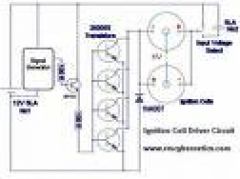
You can just replace it like for like and add a resistor (about 10k or less) between the gate pin and GND. The best way though is to use a MOSFET Driver.
How i should connect an IGBT instead 2n3055?
Many thanks…
khush,
Eh?
student,
The output waveform is not square, it looks like this.
lets say on the input i apply a square wave what type of waveform will i get at the output. i know it will be high voltages bt im wondering if it will appear the same as input but amplified or same as input aplified and biased.plz help im in a tight corner!
hellow i wud lyk 2 know what type of insulation wire u can use to connect on the spark area when using the coil for projects instead of a spark wire or plug?
First I must recommend you don’t use an MOT if you are not experienced with HV.
The current limiting effect of a capacitor can be calculated as follows.
The reactance of the capacitor (measured in ohms) is;
1 / (2*pi*f*C)
pi is 3.142, f is the mains frequency, c is the capacitance.
You then use ohms law to calculate the current that can flow.
I have A question about a Microwave transformer if you could please help? I want to limit the current to the transformer im going to connect my 25uf ac cap in the positive line then into the transformer to limit its current will this work ok? is 25uf good for a microwave transformer? Its going to be a jacobs ladder, also how long can I run the transformer before it gets to hot? thankyou. PS love your site
Not quite the same because the gate pin is ‘seen’ as a capacitor by the driving signal. You will need to place a resistor (about 2k – 3k) between this pin and ground to make sure the pin goes low correctly during each cycle.
How can IGBT’s be connected to this circuit. Is it the same as a standard bipolar transistor?
Thanks!
Breadboard is not suitable. You need some wire capable of taking at least 5 Amps for connecting wires to the ignition coil and battery. The other wires can be smaller.
The parts list is all there. The capacitors and resistors do not have codes, you just buy something of the same value.
I’m a student trying to build the top ignition coil driver circuit. I have a couple questions:
1) What wire gauge size should I be using to connect each component? Is connecting all the components through a bread board OK?
2) You have provided a parts list, but only some have their actual code provided (i understand that each part code will depend on the type of ignition coil used), but is it possible for you to provide me with the list of parts you used, so that i may compare to what i should be using?
I am using the cylinder type bosch ignition coil .
Thank you and any help will be greatly appreciated.
You would need to have a signal from the hall effect sensor that goes high when you want the coil to spark. You would feed the signal into a circuit like this where it says “Modulation signal”. I can’t give you anything more that that really as its specific to your own project.
If I wanted to use this on a bike motor, could you tell me how to incorporate a hall effect switch and recomend the parameters the hall switch would need?
ducatidragon916,
Ideally the transformer for a multiplier needs to be a proper AC output, the output from an ignition coil does not reveres very much so they are not great for driving a multiplier. A pair of them used and pulsed at opposite times and with opposite voltages would work much better.
What energy X-rays are you trying to produce (100keV, 1MeV ?) I would assume it would be in the lower keV range otherwise you would need a long accelerating tube for the electrons. Is your purpose for X-ray imaging? If so then I guess the high current is important so that a good exposure can be taken before the subject moves and blurs the image. Since this would be a short burst of X-rays the best way to achieve the stable HV and high current from batteries would be to charge a large HV capacitor with the multiplier, this would then need to be dumped into the accelerating tube through a resistor in a controlled way.
newbie, carlo,
Any NPN bipolar transistor rated similar to the BFY51 will be fine. (capable of 1A)
sorry, it’s me again. i was mistaken. i only have the 2N3904. can it substitute for the BFY51? thank you very much.
hey, can’t find BFY51. i have three NPNs, 2N3904, 2N1613 and 2N2218A. which is better?
can i use this to drive an electromagnet coil?
hi, i can’t find BFY51. any substitute for that?
That is precisely what I am attempting to do. I am trying to power an xray tube with a battery configuration for portablility research. I am trying to produce a working unit to test and perhaps manufacture. I understand the dangers of xrays and the shielding required.I have radiation detectors and lead shielding to protect my self or anyone else etc. I just need to be able to attain these high voltages in a hand held configuration to experiment at this point. I have built several ( glass blown) xray tubes which i have made much more smaller than the manufactured units out there. So i just need a stable high voltage PSU with the most current output with a multiplier stage to produce enough power to run the tubes within 20-60 ms range. Any ideas?
Thanks
The heat generated inside the transistor comes from several sources but generally it i proportional to the current flowing through it. When there is a spark, your coil is essentially short circuited and therefore drawing a lot of current. You need to screw your transistors to a large heatsink for them to stay cool and work better.
The brightness (temperature) of a discharge is proportional to the current flowing through it. Creating very high voltage is not necessary and can produce dangerous x-rays when applied to vacuum tubes. It would be more efficient to use a voltage that is just enough to start the discharge and to use as much input current as possible.
I wanted to add one more thing. The multiplier circuit wil run around 60 -80KV. So i need the most current i can get out of this portable configuration. Any ideas or thought would be greatly appreciated!!!!
I have been testing out circuits posted here with a MSD ignition that is rated to 48kV. The input resistance and output is .44 ohm and 3.1kohms respectively. Inductance is 7mH and the current is 300mA. I am not going to use the HV to create sparks rather…I am using it to use in HV experiment in vacuum tube discharge. I will be using a multiplier circuit in conjunction with this HV generator. My question is how to gte the most efficieny to produce the most highest potential and current for the tube discharge. I have been using the 555 timer with MJE13009 and 2SC5244. They both have been getting hot and especially when I spark them which I am doing to determine voltage level and current. Any suggestions to making the circuit run cool and efficiently for discarge tube?
Thanks
The diode D1 in the top digram is used to protect the transistors from reverse voltage. Ideally it would be a Schottky diode but a common one like a 1n4007 will provide some protection.
Placing the diode across the load as you describe will cause the diode to absorb the whole reverse voltage spike which will be large like you say. The RC circuit does work to absorb spikes (the resistor heats up too) but it is going to reduce the possible output voltage of the coil. When your capacitor is charged or there is nothing on the output of the coil there will be more EMF because the energy is reflected back.
Hi, I have been looking closely at the PSU for the tesla coil, and I am currently finding it very useful as I am doing an A-Level physics projects comparing the length of sparks to the conditions which they are being created (voltage, heat, water content of air). So for this I am just using the primary circuit, and nothing after the capacitor bank, as I do not need amazingly high voltage to conduct the experiment. I just have one question about the design. Would it not be a good idea to connect a diode allowing pass from the -ve to the +ve terminals of the ignition coils. As I may be putting my transistors in danger of the high EMF induced as the coil is switched off. I see the little circuit the with the cap and resistor, but is that really enough to take the possibly very large induced EMF? I have tried this with and without the diodes (running for a sort time) and when the diodes are in place, they get very hot, showing that there is in fact a lot of current going through them. Do you have any thoughts on the matter?
Thanks very much,
Sam.
Thanks… I have tried with a battery (I assume a battery can deliver a very large current)but I still get very small sparks. Will check the 2N3055
I use 12V SLA batteries for a power source. They are smaller than a car battery, can provide more than enough current, and will not be ruined by back EMF.
I can’t say for sure why your sparks are small, but I would expect the coil to draw more than 3.4A at 15V. It is possible that your PSU is limiting the current too much.
Hi RM – hope you are okay. I managed to have your circuit working with a computer transformer (16V, 3.4A) now, using one 2N3055 and one coil. However sparks are very small – around 2 mm. When I replace the load by a 470R and plug a scope in parallel to that resistance, I get a clean, 15.2 volts square signal of which I can change the freqency and duty of with the sig. generator (best sparks around 1KHz). How come the sparks are so small? I also tried a 12V car battery – I also get the same small sparks. This coil was fine when used with a dimmer and capacitor for a Jacob’s ladder – Many thanks Thomas
Hi RM, what power source would you recommend for this project, apart from car batteries? I tried a laptop charger (says 16V 3.4 A on the specs) but it does not seem to work. Same question for your Power Pulse Modulator Kit – do you need a car battery or are there lighter (!) alternatives you’d recommend? Many thanks Thomas
It will work to some extent but I can’t say how well. Yes BC549 and BC549C are equivalent.
Also, is the BC549 the same as the BC549C?
Here is a schematic for a square wave generator I found on the web. It is the only chip-free one I’ve found. Would it work as the signal input for your driver schematic?
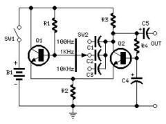
There are many ways, several of which are already discussed in the comments. The 1n4007 is used to protect the 2n3055 from reverse voltage spikes.
Your 555’s are being destroyed because energy is being reflected back from your ignition coil in the form of high voltage transients. There is some info on how to protect against this in the article and in the comments.
Is there any alternative to using a 555 timer to create the signal? I’ve been using an astable 555 circuit and so far have blown through at least 10 555’s! At a dollar a piece, this is getting expensive 🙁 Also, what is the purpose of the 1n4007 diode in your top schematic?
Please read previous comments before asking a question. It has been answered here
For the 2N3055 power transistor: the transistor I have has two pins, neither of which are labelled. The schematic on the PDF labelled Further information on 2N3055 on this site http://www.maplin.co.uk/module.aspx?ITAG=SPEC&ModuleNo=33878&doy=12m12#spec shows them as (1) and (2), B and E respectively – but this is not indicated on the component itself. How can I tell one from the other? And what does C (TAB) refer to on this schematic?
Thanks.
Yor diode must be either in the wrong place or the wrong way around. The end of the diode marked with a stripe must be connected so that it normally ‘sees’ a +ve voltage. This would mean it does not normally conduct (i.e. it is reverse biased).
Alright so I tested it out again today, after replacing the diode. The first time I tried it out nothing happened, but it was working perfectly the next time! Turned out the diode had fallen out between the first and second attempts. So it works when the diode is out, but not the the diode is in. Now im even more confused!
I would guess your diode is the wrong way around and thefore shorting out the power.
Hey, I recently finished you driver circuit [the simple one], but when I turned it on, the diode started smoking and eventually cracked in two. I’ve double-checked my circuit and it all seems good. It only smokes when both batteries are providing juice, and when the ignition coil is hooked up. Any ideas?
Once you have had significant arcing at that sort of power it may be hard to prent further. Any burning on the insulation will conduct and eventually lead to a permanent short circuit. You could try oil immersion, but like you say, it can be messy.
I’m no expert in ignition coils and have never even seen one like the one in the image (looks cool though). I couldnt really suggest what the best type to use is. Let us know how your project goes.
Working on a Jacobs Ladder
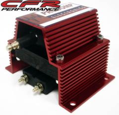
Using 555 pulsed circuit with Mosfet driver IRFP450 and paralleled auto ignition coils, upright oil filled type.
With the circuit tuned well, I can get hot streaming arcs up to 9-10 cm but having problems with arcing from the HV out terminals to the primary coil terminals on top, very bad on one of the coils where there seems to be a small crack in the housing. Since I have the input AC on a Powerstat, I can bring the volatge up slowly to see where the arc begins on the ignition coil out to the screw terminals. Even with some insulation, at full voltage there is some arcing everywhere over the tops of the coils. The two ignition coils I currently have are different brands but similar upright cylindrical, oil filed types. Only a problem when I try to get a long spark. At 1-2 inches there is no problem. I have HV wires soldered to the screw terminals and I tried to insulate the primary terminal with hot glue last night but no go.
Is there anything that can insulate this area to stop the arcing? e.g. Silcone putty, Hot glue, mineral oil emersion (messy) etc??
If not, should I just buy another set of ignition coils on ebay?
There appear to be many kinds of coils and I was told that certain types do not work well with the solid state driver circuits….e.g HEI type shown below.
Which coil will give the best arcs, HV out and durability? Cost no object.
Procomp below has primary and secondary terminal far apart, may reduce arcing??? Not sure what type it is???
Procomp Ignition Coil
ProformHigh Perf 66943C HEI Ignition Coil 50,000 Volts
Crane Cams – GM External Ignition Coil PS-91 Fire Ball
One website said the first coil shown above was no good…” Pro-Comp…Chinese masquerading as Australian, run as fast as you can away from that junk.”
Thanks much for any help!
Dan
try to add diffrernsiator circuit before coil input… it can make flucktuative pulse in AC
YEs, you should definatley use opto-isolation! MOVS can be purchased that will work in one direction only which may give improved reaction time over a seperate series diode. The HV spikes will be produced in both directions due to ringing, but snubbing the initial reverse spike might be ok.
Thanks DB, will give that a go.
RMC: Im planning on adding audio modulation to my driver, and im just wondering would it be wise to use opto-isolators on the inputs to the audio modulation, would this kill any risk of smoking my laptop/signal generator? Furthermore, for feedback protection across the load would an MOV with a series resistor and series diode (facing -ve to +ve) help eliminate feedback without shorting out the power to the coil? Thanks for your help.
Richard, I used a 2N2219 instead of the BFY51. It’s a TO-39. Fast. Jameco sells them. They work pretty well.
Richard J (NZ),
Match coils will work better. BC139 should be ok if you have a resistor to limit the current like shown in the diagrams. A larger one might be better though.
Simon Dodd,
The current limiting will just reduce the max voltage you can get. It should still work noticeably. You can put a speaker in place of the coils to test the circuit (it should be pretty loud).
I think I have found the problem but I want to be sure before I go out and buy more equipment!! The power supply unit I am using limits the current at 3A! Would this stop the ignition coils from stepping up the voltage or should they step up slightly even with a lower current going through them. Also can I connect a speaker to the output of the 2n3055’s to test that section of the circuit, if not where are the best places for testing. I recently discovered my osciloscope is extremely faulty and am thinking of building a new control circuit for it using the same box and switches as I thoguht this would be easier than trying to repair it.
thanks again for all your help
Simon
ps I am building the second circuit on this page.
When running two coils in anti-parallel, do the two coils have to be a matched pair with similar/identical resonant frequencies for maximum output? Furthermore, I can’t get a BFY51 transistor, the closest i can get is a BC639, which has a TO-92 case instead of the TO-39 case of the BFY51. Will this get smoked and/or will I need a second preamp transistor to drive 4 2N3055’s.
Cheers
This MOSFET Version uses an IRF740 (400V 10A)
The 2n3055s collector terminals are connected to V+ via the ignition coils. When the signal at the base pin goes high current will flow from V+, through the coils, and then through the transistors to ground.
Gday RMC, just been having a play with this circuit and thought that 2N3055’s are kind of an ugly transistor due to their high base drive demands and low (100V) max operating voltages. Im thinking of using high power mosfets instead because of their lower drive demands, and higher operating voltages. Ive estimated that the voltage on the primary of my ignition coil is around 400-500V, any ideas for a suitable mosfet. PCB artwork coming soon for anyone whos interested. Cheers
I have built the second circuit on this page using your signal generator which works great. The circuit is pulsing (i have tested it with a speaker) I think I am having some problems with the wiring of the 2n3055’s, I have 4 of them mounted but I don’t understand why the collectors aren’t connected to V+. surely there needs to be a voltage across the transistors that is switched by the base input. I seem to still be having problems with my ignition coils as well but this could be because of my problems on the power transistors.
thanks again for all your help
i have a circuit that works much like a impending transformer only for square waves though but i just need a high current switch that produces the main square wave. feed bacik is no issue with my cicuit its just a small tc and i have an input of 40 to 120vdc rectifiyed dc.
inga,
Yes you could use a high frequency sinal instead of the V+ connection to the coil. The flow of current (for the same voltage) will be significantly reduced though due to the reactance of the coil.
A 2n3055 is not suitable because it has a breakdown voltage of just 100V. IRF70 is a good MOSFET for dealing with switchmode power as it has a breakdown of 400V and a current of 10A. It is also avalanche rated so an over voltage breakdown will not destroy it as long as the current is kept below 10A.
A true SSTC is not a simple thing to make. They are prone to destroying your MOSFETs. Preventing this involves overcoming many technical chalanges which are beyond the scope of this article.
DB,
The 1n4007 is there do do this in both diagrams. Diodes have alimited response time though so it is not always effective. A schottky diode would be better if it had sufficient power ratings as these respond quicker.
The interfernece is not just reverse polarity allthough the initial large spike may be.
I’d hate to bother you further. But I will.
How about hooking up a high voltage, high current diode across the + and the collector of the transistor?
Isn’t the interference of reverse polarity of the input? Shouldn’t that just short out the back EMF?
the main dc power supply lol i dont think it would effect it but if i was to use a mosfet what type would be most usefull? or will the 2n3055 work for heavy current switching such as a primary to a tesla? im making a sstc and like this simple design as a basic structure thanks for your advice
I’m not sure what you mean by replacing the DC with HF. Do you mean the DC supply to the coil or the square wave signal input?
dear rmc
refering to your ignition coil driver at the top would putting a high frequency through the circuit instead of dc affect its operation in a way that it will not switch ? also i plan to use a mosfet but have no clue as to what type i should use or how to identify which pin is which thankyou
p.s i dont think that the 2n3055 would last very long for my plans lol.
DB, Putting chokes there wouldn’t really work, but you could put one between your battery + and the signal gens + input. The snubber using capacitor needs a resistor too to work properly. Arcs to the coils input terminals is ok if your snubber arrangement is working.
Cracking resource page, answered all my questions without posting a thing, Thanks!
Well, thank you. Glad I didn’t do that. I have however experimented with the capacitors. At one point I was using a 1MFD capacitor and no resistor. Even then the neon was lighting up and the comparator died.
I switched the 339 for a 393. It dies too.
What about using a choke on the wires that go into the coil?
Oh, and it’s a bad thing if the arcs come out of the top of the coil and strike the inputs?
Is is bad that corona appears traveling through the alkyd tower thing and into the inputs?
The resistor in the RC snubber dissipates the excess energy as heat. Most common POTs are not designed for any power and would be damaged quite easily if used like this.
I’m thinking that I will take a microwave oven capacitor and put it in parallel with the low voltage leads. I will uses a 10K variable resistor to adjust it until the neon light stops lighting.
Yes you can snub spikes at the source and you can also place devices between your power rails to prevent unwanted voltage levels. You can place a few capacitors of different values in parallel with the supply to smooth out any oscillations. A MOV could also be used here to limit any remaining voltage spikes to safe levels.
I am using a LM339 quad comparator. Not the 393. Might that be a problem? I don’t think it is.
For protecting it, should I employ the snubbers you have?
I am using capacitors and neon.
The neon i’m using is a module with a built in resistor. I think it’s 33K. Should I remove this resistors or replace it?
ohio texas,
Separate drivers can be used, but they must share the same input signal so the coils are pulsed at exactly the same time.
DB
You need to adequately control the back e.m.f produced. When you are driving the coil and there is no arc, massive amounts of e.m.f are getting back to your circuit. This is because you are pulsing energy into the coil but not absorbing it on the output, the only place for the energy to go is to reflect back into your circuit. You must absorb this energy before it gets to your 393.
Whenever I draw arcs, it seems that my comparator dies. The signal becomes very flat. I’ve had to replace it a few times.
Everything else is fine. The 555 is fine. All the transistors are fine. It’s just the comparator. Time after time. It’s an LM339.
Oh, and I found this circuit works a lot better substituting 2N6547 for the 2N3055.
dear rmc
will placing two transformers running on different drivers still inceace voltage if connected or do they have to be connected to the same driver?
This is discussed following post 1001
how does 12 volt ignition coil converts 12volt into 15kilo volt to 40kilo volt plz give me mathematically equation and
dear rmc
your neon globe design works perfectly in protecting the 555 timer circuit plus rc1. im putting more in parrallel to run my flyback i just wanted to thankyou for all your help, laters
yes
Have you actually tried googling “square wave to sine converter” or something like that?
how can you turn a square wave generator into a sine wave generator ? i was thinking of putting a zender diode in parrallel with the wave but then again i have no idea please help thank you.
The 555 was working fine far as I could tell. I replaced it just for good measure, still nothing 🙁 I’m getting a bunch of new 3055’s Wednesday though. Hopefully that’s the problem. Also for all people considering this project, I recommend you spend some time with your breadboarding, it will save you from a lot of troubleshooting.
yes sorry its me agian , i have designed a new circuit that should reduce emf voltage its hard to read, its an add on to your circuit posted at the top’ i still have rc1′ . this circuit uses 1 impending matching transformer to transfer load , 2 high voltage chokes ‘ i read some comments’ 3 1000v diodes ,2 hv caps and the light indicator , basically its over done but tesla coils have a lot of feedback let alone running the flyback,
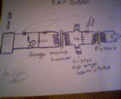
Yes. Chokes are used in the plasma gun project.
will a high voltage choke help reduce high voltage feedback? it seems to work on neon transformers.
Bob Dole,
I would guess the 555 is blown. Are you able to verify that it is oscillating?
jason t-bert,
Yes, if the output of your coil is connected to a load there will be much less back EMF produced.
if you dont draw long arcs with you flyback will this help protect your circuit for exsample if i had this driver running my flyback charging a main cap will this reduce violence in my 2n3055?
Hello again! Yesterday I finally managed to get your driver [the top one] up and running. I was toying around with it, and a large arc jumped between the HV output and the negative terminal of the coil. Since then it has stopped working. I am using my own 555 timer astable circuit to create the square wave. I tested that part of the crcuit by using an LED indicator light and it seems to be functioning fine. So far, I have replaced the 3904 transistor [which I am using as my small signal transistor], all of the resistors and capacitors, and the ignition coil itself. I only have one 2n3055, so I haven’t been able to replace it yet, but I did test it using a simple test circuit [see picture], and it seems to be functioning fine. I am at a loss. Do you have any idea what could be wrong? Any help is appreciated.
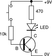
If you want to snub out the spikes at the source then yes, but this can effect performance. The basic idea is that you place a MOV between any two points to limit the voltage that appears there. For example; If your transistor has a max Vce of 100V, you could place a MOV rated for 90V between c and e (collector and emitter).
Should the mov be placed over the + and – points of the coil?If not where should it be placed?
Thanks a lot!
Albert Como,
No.
justin,
Wax will help prevent unwanted arcing but don’t forget that wax is a hydrocarbon (a fuel) and will burn when soaked into things.
No your varistor will not be adequate. It will only activate at around 275 volts. If you are using a 2n3055, then the max voltage it will take (Vce) is 100V. You need a varistor that will activate just before 100V, or a transistor with a higher Vce (Vds for a MOSFET).
dear rmc i found a metal oxide varistor but i have no idea if it will work on my 12v circuit so if i specifi it can you tell me if it will work or not?
maximum operating voltage 275v AC
pulse energy rating 20 joules
peak pulse current 2000amps
device types ve17mo275k, 275A20A, TNR15G431K,INR1D431,TVR14431
$ 1.50 i dont know if this would work or not but a varisitor seems more efficiant for this circuit.
my picture did not send urrr ohh well its pretty similar to yours only i have two caps in parrallel and two sets of 1k plus lights in parrallel and two 6amp diodes in the same direction in serires plus transistor protection lol i really dont want to blow my circuits , my caps are rated at 0.1uf 3000 volt tolerance, aside from all this i have a problem with my magneto coil , its not made for high frequencies and so as a result discharges between the hv out and primary i was thinking of pouring wax around the transformer to prevent this discharge would this work?
I’m using a square wave generator. Could I use an SCR instead of the power transistor?
Just added a bit more info to the article about protecting circuits.
hey its me again havent been here for a while but i have a problem lol im trying to run my tesla through an ignition coil but nasty feedback screws my 555 so i thought of this simple circuit wheather it works or not i dont know but i wanted you to cheack over it if thats ok by you otherwise never mind.
Many other transistors can be used. This circuit uses a mosfet.
yer i read it but dosent state how to protect my ic chip i iwll try thr indicator using the 1kr and the light bulb thats a good idea yes but still does not protect my ic also would a mosfet be more effective in this circuit i herd that the 2n3055 acts like a resistor when in circuits like this?
Dave,
1) Yes that is a good way to protect your circuit.
2) There are many ways to do this. You could place a mov across your load but this would add capacitance (decreasing dI/dt) and would need to be rated to dissipate a reasonable amount of power. Placing one between c and e of the transistor would also work if it were rated for similar power levels.
You can also place a MOV or zener diode between base and collector so that the transistor automatically switches on if the voltage is high.
john,
Yes, read the information on this page.
instead of using the signal gen. i used my
ipod playing a constant tone.
it works great!
i built your crcuit but instead of the byf51 npn transistor i used the basic square wave circuit but after 5 minytes of 7.2 volts the timer blew and i had 6amp 1000v diodes in each direction of the out signal wires it only worked for so long can you suggest why im having these problems thankyou
Thanks for the helpful info. I’ve got two questions, though:
1) Would it make sense to optically isolate the signal generator section from the power stage (e.g. use the phototransistor of an optoisolator as the first stage of the Darlington pair)? Then if back EMF roasts the optoisolator, it wouldn’t affect the comparator and 555.
2) Where would be the best place for a varistor in this circuit? Would it be across the primary terminals of the coil, or between the collector and emitter of the power transistor? I’m thinking the latter option makes more sense, since it would shunt any high-voltage EMF to ground and (hopefully) bypass the power transistor (sparing it from an untimely demise ;^) ).
Thanks in advance,
Dave
Sounds like a damaged 2n3055 to me. If you are making sparks, the ignition coil will make a huge amount of back EMF whenever a spark stops. If you have nothing (like a snubber or MOV) to limit the voltage of these EMF spikes, they will damage your drive circuit.
My circiut was working perfectly for some time,but all of a sudden it lost a lot of power,The output voltage became very poorand the 2n3055 transistor becomes very hot as soon as i apply power to the circuit.Can a blown capacitor on the rotary switch be the cause?
Yes. The current flows out of the +9V battery through the signal wire, then through the drive transistors. There needs to be another wire returning to the other connector of the 9V battery to complete the circuit.
Even if it’s being powered by a separate 9v battery?
Yes, because the current from the output of the signal generator will only flow if it has a path to the ground of its own power supply.
Do the grounds from the signal generator and 12v suppy have to be common? If so, why?
I’m not sure how you are getting this square wave. Ignition coil drivers are prone to failure unless careful attention is paid to reducing back emf. The article above has been updated with a little more info regarding this.
not yet but i have a square wave for some reason the second wire is ground lol thats what i meant i just need a simple driver to run my tc that has a long life because all my other drivers have a classical fait after a 1 min run
There is only one input signal wire. How is crossed? A relay is a switch, not a signal source. They can be wired to oscillate though, is this what you have done?
you know that driver circuit you have posted at the top well i noticed a square wave effect when the input signal wires were crossed. if you have a relay in series with a 1k varible resistor could you use this as you signal supply 1k been the frequency conroller. please relpy soon.
Danger of what? Fire, electric shock, RF interference?
If there is no mains voltage and no HV capacitor on the output, then the electric shock is unlikely to kill directly. It could still make you jump or cause muscle reflex which could indirectly hurt you or someone else.
If all metal parts are insulated and the coil is running at high frequency, then there is little danger from touching the glass.
You still need obvious safety measures like making sure things aren’t getting hot or internally arcing.
How significant is the danger from this driver when used to create a plasma globe?
Your supply is likely to get damaged unless you are able to suppress the voltage spikes effectively.
Would it work to run an ignition coil directly off of a 12v power supply for spark gap experiments, or would the voltage that occurs on the primary side of the coil when it is discharged be likely to cook the power supply? I’ve emailed a couple of people about this question, but haven’t gotten a response.
Thanks a lot for your help.
Wait, you mean put in on the pin 1 or 8?
Or do you mean in series with the ignition coil?
Either pin, but it is most often placed between +ve and your device. A Voltage regulator would be better.
Where do I put that 100 ohm resistor? On pin 1 or 8?
On the connection to the comparator? On the whole circuit?
Can I have a voltage regulator chip on the VCC of the 555?
Bob Dole,
Common ground is just a connection between the ground, 0v, or -ve terminals in seperate circuits. e.g. To connect a signal source with a 9V battery to the ignition coil driver a wire is connected between -ve terminal on the 9V battery and the -ve terminal of the 12V battery. This is your common ground. You can then connect the signal output of 1 circuit to the signal input of the other.
Albert
Yes, See above. It should not fry on 11 V. You probably just need to limit the current with a 100 R resistor.
The 555 is fried when ever I bring the voltage over 11 volts. With or without the coil.
Is is possible to run the signal generator off of a separate 3v source and run a full 12 through the 2N3055?
What is the common ground?
kerk man red,
Yes most npn transistors will work if it has similar current and voltage ratings.
john redcorn,
100 ohms is still ok for 9V.
Bob Dole,
A neon or fluorescent light will glow when connected to the HV output
How can I test the circuit to see if it is producing an HV output?
Different coil types will not work so well together. Each coil will have a different resonant frequecy at which it works best.
Yes you can, if they are all the same model coil.
Alright. Hopefully my last question. I have 3 different coils. They are all different types. Will hooking two of these up in anti-parallel work, or will their frequencies be messed up or something?
And can I do a set up where I have 2 parallel sets of coils hooked up in antiparallel? (4 coils. 2x voltage. 2x current)
dear rmc i just made the circuit that you have posted up the top and it works but i noticed that when a dc signal is applied the oscilloscope shows that very same signal been interupted is this normal. i also wanted to know that if i apply a 9v signal what resistance should i use so i dont blow the npn gate transistor’byf51′ im not sure but i think it only needs about 3 to 4 volts to drive it but i have no clue as to what resistor i should use. thankyou for your help it will be much appreshiated , i should use a varible resistor in case of different applications
dear rmc with your ignition coil plans at the top i have most of the components but have a couple of questions: will any npn transistor drive the 2n3055 transistor provided within the voltage range?’meaning tolerance’ and will any diode say about a 6 amp diode work on this circuit instead of the one posted? thankyou for your help i plan on making a wave generator that can sweep up to 10khz to 100khz and i wanted to know if i could find resonace of my coil withing these ranges thankyou so very much i love this site only one like it around keep up the good work.
Nope. You have a couple of things wrong. Don’t use the spark plug cable. It uses a carbon based material for the conductor which has a high resistance. You need to use a normal wire with a metal conductor.
The light bulbs electrical connections should be shorted (linked together), then a single wire from this should be connected to the HV output of the ignition coil. This makes the fillament inside the bulb at a high voltage compared to the ground (and surrounding objects). The plasma filaments will reach out for grounded objects placed near to the bulb.
It’s best to keep HV wires as short as possible so that energy is not lost to the surrounding air. The best way to connect your bulb is to stick it right onto the output of the ignition coil with some wire or foil inside to make the connection (like this).
Oh sorry, I’ve hooked the HV output up to a light bulb to create [hopefully] a plasma globe. The terminal on the bottom of the lightbulb is connected to a spark plug wire connected to the HV output, and I have part of the light bulb that actually screws in connected to the ground of the driver. Is this right?
The switch allow you to select 12 or 24 V operation.
What light bulb?
The signal generator can have its own battery or just run from the same source as the coil
Does the ground on the first schematic connect to the “side” of the light bulb? Also, I am using the dead bug signal generator. Does it require its own 9v battery for power? I’ve set up the project on a breadboard and tested it out. So far nothing has happened. I disconnected the light bulb and help a screwdriver in the HV output of the ignition coil, and no spark appeared. What possible issues should I be looking for, other than the basics? Your help and website is much appreciated.
I don’t understand why there is a 3-way switch. Shouldn’t there just be a simple on-off switch?
Anti-parallel will cause the output voltage to be of the coils to be equal and opposite (when one is +10kV the other is -10kV). The spark would jump between the two output terminals. The two output voltages are considered to be 180 degrees out of phase.
When in parallel the outputs are in phase. This means that the voltage between the two outputs will always be zero. If the outputs are connected together they will operate as a single ignition coil would but with the potential to deliver 2x the current.
Why does antiparallel double the voltage when parallel doubles the amps?
Is the output the two output terminals connected or does the spark jump between the coils?
Antiparallel refers to placing polarized (has a + and -) component in parallel but with the opposite polarity to each other.
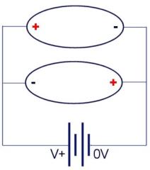
What’s the difference between anti-parallel and series?
More than enough. You will probably need 1k of resistance and about 1uF capacitor in series. The resistor will prevent the transistor from blowing and the capacitor will block DC. Start on a very low volume to test things out. I would also reccomend replacing the ignition coil with a speaker while you get it working.
Also don’t use your PC or anything expensive as your audio source if you are modulating an ignition coil. There is a high risk that you will damage your source.
Look for info on optoisolators for keeping your audio source electrically isolated from your HV circuit.
would a typical head phone port be enough power to switch the byf51 transistor and when you state the resistors and diodes could you please state the values i havent advanced this far lol your too smart for me i dont get some of the basic stuff lol love this site very unique
A small note on the RC component of the circuit. The effectiveness(ability to produce sparks) is reduced with the exclusion of the R from the RC filter since this effectively defeats the switching function of the transistor.
In fact, the resonant frequency generally increased with increasing resistance. This seemingly paradoxical behavior is due to the non-linear character of the diode.
Just a small note…
Placing transistors in parallel theoretically will give you more current handling, but it only works to some degree.
Each transistor will switch at very slightly different times due to manufacturing tolerances. This has two major drawbacks in this application.
1. If the peak current exceeds the capacity of a single transistor, the first one in the array to switch on is likely to get destroyed. With many cycles happening within a second you can blow several transistors quite easily.
You can prevent this from happening by placing a current limiting resistor in series with each transistor. This will protect the transistors but it is not efficient because a lot of heat is generated when the high current flows through a resistor. One reason multiple transistors are used here is to reduce the total ‘on resistance’ which allows more current to the coil.
2. The output voltage of the coil is proportional to the rate of change of current in the primary coil. With an array of transistors, they are not switching together so this rate of change is reduced slightly. The added junction capacitance also increases the time it takes to switch off.
The TIP3055 does switch off pretty slowly compared to the BFY51 (1us vs 60ns). You probably don’t need a preamplifying transistor anyway if you are using just one 2n3055.
To get the full output of your ignition coil you must ensure the transistor is switched fully on before it is switched off, and you must switch it off in the shortest time possible.
I built a very similar circuit myself. The only differences though is that is uses only 1 2N3055. and instead of a BFY51, I’m using a TIP3055. I’m only getting 1 cm arcs. This is supposedly a 42000 volt ignition coil.
I wondering what you think the problem is. I think that I need to switch the TIP3055 with something faster. The TIP only does 3MHZ. I don’t have a BFY51. Could I just get a few fast, low current transistors and hook them up in parallel to meet the current requirements? Do you think that a faster switching transistor would solve my problem?
When a single wire is shown like this in circuit diagrams it represents a signal/voltage with respect to ground. This means that if you are connecting two circuits together (your audio source and the coil driver), there must be a common ground between them. A common ground is created by simply connecting the ground point of one circuit to the ground point of another circuit with a single wire.
I can only guess that one of the wires in your pair is ground, the other will be signal.
Like I already mentioned, I don’t think this will work properly with a self resonating design. The frequency generated by the self resonating circuit is equivalent to the HF drive signal, but if you start trying to modulate this the feedback loop will become unstable and therefore cause the drive frequency to change.
Yes, almost any npn transistor will work if it rated for the voltage you use.
Two or more 23055s can be placed in parallel to allow for more current.
Hello. Would it be possible for me to replace the BFY51 Transistor with a 3904? Also, I see that under the parts list it says “2n3055 Power Transistors”. Is this a typo or are there actually two of these transistors [I can see only one in the schematic]? Thanks for the help.
The HF signal is a single frequency square wave from a 555 timer or any other signal generator. This is what you have in a typical ignition coil driver to make your arc. You then modulate this arc with your audio.
What second audio input?
i get how it works but what is the HF drive signal and were does the second audio input go sorry baout all this but thanks again for the help. i was planningon using a self resonating design could this be impamented some how thanks.
could you please post a simple design its hard to understand in words lol sorry , i am good at electronics but i cannot make the connections in my head.
The diagram just shows the basic components. You will still need to add things like RC1 and a diode.
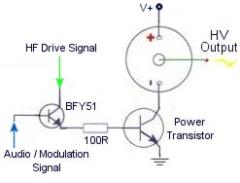
this diagram shows how a BFY51 transistor is used like a switch or valve for controling how much of the HF (high frequency) signal is allowed to get to the power transistor.
With 0V placed on the modulation input, the HF signal will be blocked and thefore the power transistor will not switch on. When some voltage is applied to the modulation input, the HF signal can pass through and drive the power transistor. The level of the HF signal reaching the power transistor will be proportional to voltage applied to the modulation input. Therefore if the modulation input voltage is varying with time, the output power of the ignition coil at the HF drive frequency will vary with it.
Sam,
They have not been designed or tested for use with engines, but the circuit does drive auto ignition coils. Your suggestions seem sound, but I couldn’t comment on the effectiveness of an arc ignition compared to a spark ignition.
alan swane,
It may be possible to do it like that but I would excpect a lot of distortion in your input signal caused by the feedback/self resonanting system.
The best way is to drive the HV supply (a flyback or TC) at a set frequency which is high enough to be inaudiable to humans. This signal is then amplitude modulated with the audio signal which you wish to hear.
For example; you have a driver like on this page driving an ignition coil at a set frequency. You would disconnect the signal from the base pin of the 2n3055 (or equivalent) then connect it to the collector of another transistor (such as BFY51). This transistors emitter pin would then go to the base pin of the 2n3055s. You can now add your audio signal to the new transistor. The audio signal would dynamicaly alter the resistance of the transistor so that the power level of the drive frequency becomes proportional to the audio input. Of course there may be a need for a few R’s and C’s to keep the voltages in your circuit correct. Now any arc could easily be modulated with audio.
dear rmc
im interested in musical tesla coils but need some background information first: for a solid state tesla if you use say a simple design like the self resonating flyback could you just add the music input into the feed back wires to switch to the frequency of the musci? thank you for your help.
Can one of these circuits be used in place of a regular auto ignition system –
e.g. – Have the HV generator running constantly and switching the HV to multiple spark plugs (according to ignition timing) via some thyristor.
or – Have multiple HV spark generators (one for each set of spark plugs) and turn them on/off according to the ignition timing.
For a 4 cylinder engine – 4 sparks per revolution @ 750(min)/8000(max) RPM -> 3000(min)/32000(max) sparks per minute -> 50(min)/534(max) sparks per second or Hz……
In theory “arc” ignition sounds better than spark ignition……
It depends on the manufacturers specs for the ignition coil used. I would expect that under heavy load with large current draw the coil could eventually overheat.
The output voltage will depend on the specs for your specific coil. It averages around 20kV
How long can this thing work Continuously? Will the coil not overheat??
Thanks your circiut works perfectly!
Any similar npn bipolar transistor will do the trick. The current drawn depend upon frequency, load etc but is usually around 5A.
difficult to find BFY51 transistor,is there any substitute.For 12v power supply battery how much amps battery is used.
Small differences in the performance of each 2n3055 can cause this sort of effect. The hot one is probably partly damaged and not switching on fully. A higher voltage on the base pins may also help ensure the transistors are fully switched.
Hello,
i got 12 2n3055 transistors on large heatsink. I noticed that they are not equally heating. One is very hot and some are cold or warm. What can I do to fix this?
Many thanks!!!1
Not practically. You need to use variable frequency source on the input.
I would like to increase the frequency of the high voltage output of my ac ignition coil driver. is there a way to make and attach a device on the secondary of the ignition coil to get a higher frequency voltage?
The internal resistor is for limiting the current in the coil to prevent damage. If the ignition coil is designed to fire more spark plugs at once, it is likley to be able to deliver more current. You would have to treer to the manufacturer for more specific details.
Hello, some ignition coils have an internal resistor others have no internal resistor witch coil is better to use for an AC ignition coil driver? Also is a ignition coil off a v8 engine give higher voltage then one from a six or four cylinder engine?
You need a device known as an RF choke or an EMI filter between your mains outlet and dimmer circuit. You can find these on eBay.
Connecting your capacitors in parallel will not cause problems if they both have a suitable voltage rating.
My ignition coil driver uses a 7.5uf capacitor for current limiting, i also have a 4.0uf capacitor, each capacitor has two terminals each. they were expensive and i want to know if there is a way i can hook them together to get more current to the coil if so i could get 11.5uf i want to ask before i try connecting them together because i think that since the one cap is bigger then the other its charge will destroy the smaller capacitor.
Hello I have made a ignition coil driver that works using a dimmer switch and a 7.5 uf capacitor it uses 110v Ac. I noticed when the coil was operating that a lamp that was pugged into the wall was flickering on and off very fast the switch on the lamp was off, im getting feed back into the house. I have the high voltage output set to arc to the negative terminal of the coil, is that putting feed back into the house if so how can i change my set up to stop high voltage feed back, the lamp no longer works i tried a new light bulb, its fried.
Double current from parallel coils. Double voltage for ‘anti-parallel’ as shown in the lower diagram
would putting 2 ignition coils in parallel double the output current or the output voltage?
Josh:
You may be able to get single sparks if you can press and release your switch fast enough. It would be pretty easy to burn out your 2n3055’s like that though.
venu:
It is totally dependant upon your loads impedance. You can calculate the current using ohms law.
Driving a common cylinder type ignition coil at its resonant frequency from 12V will typicaly draw about 5 amps.
with 12v dc how much current in amps is given as input to this ignition coil driver?
Okay the circuit is sinple enoguh but for the signal could I just use a switch and a small amount of power to trigger the spark then after that build the 555 circuit ? Otheer than that I’ll put it on a perf board and I think it will work.
The simplest way to get DC is to connect a high voltage diode in series with the output.
Using a power pulse modulator set to high frequency and with a smoothing capacitor in parallel with the output will serve as an adjustable switch mode power supply.
how can i get a DC HV output from this ignition coil driver?if possible please provide me a circuit.And also please provide me a 0-30v 3amps variable simple low cost dc power supply unit circuit diagram for my experiments.
Not directly. More input power will give longer sparks as long as it is not wasted in the circuit somewhere.
Increasing the voltage applied to the ignition coil wlll mean that it will draw more current, but it could just be wasted if the core is becomes saturated (can’t contain any more magnetic flux).
Is more current from power suply means longer sparks ( about 18 or 24 Amps )? I will use it to power Tesla Coil.
Yes you can. You may need to adjust the values of RC1 to better match your coil.
Hi,
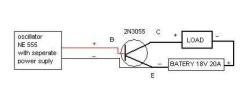
can I use this circuit to drive ignition coil ( with
RC1 and diode for protecting 2n3055 )- to have one battery for oscillator and to have an other for induction coil?
Many Thanks!!!
The power to the ignition coil needs to be switched on and off repeatedly. By applying a square wave signal from a signal generator, the transistors will switch the large currents for the coils on and off in time with the signal.
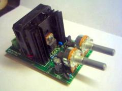
A common signal source is based on a 555 timer like this DIY signal generator.
You can also buy such a circuit with the signal generator, power transistor and added transient protection in our Cyber Circuits shop.
sorry to ask this but i am very new at this so here i go. i just wanna know what is the input signal for on T1 and what do you hook it up to?
The dimmer circuit is limited to a low frequency modulation of the mains frequency.
You will need a circuit designed for higher frequencies if this is what you need.
Our Power Pulse Modulator will drive flyback, ignition coils and almost anything else. The frequency is adjustable so you can set it to whatever works best.
Hello i enjoy (trying) to make all kinds of high voltage devices my last was the dimmer capacitor and ignition coil, what i wanted to know is could i use the same circuit i used to power the ignition coil to power a Flyback transformer? or is there a (very simple circuit) i could make to power the flyback i want to have high frequency electricity i can,t get that from an ignition coil……thanks
JimmyFromAus:
You seem to be missing the point. People are here and asking questions so they can learn new things. Were you somehow born with the knowledge you have?
artemoonlv:
The 2n3055 needs a resonable current for it to switch. Unlike a MOSFET, these often need more current than an IC (like a 555) can supply.
Why do we need pre-amplifying transistor? BFY51? why we cant just send signal directly to the 2n3055?
Ignition coils will not come close to the power output of your NST. They do not have any current limiting built in. It is common to drive them through a large power resistor of a few ohms.
For a saltwater cap the water needs to be saturated with salt (no more will dissolve). Also avoid aluminium as the electodes as the salt water will cause them to oxidise on the surface and give poor conductivity.
You can find the HV caps and RF chokes on eBay.
I have a neon sign transformer rated at 15000 volts at 30 millamps i use it for a Tesla Coil,is the current of 2 ignition coils in parallel close to or higher then 30 millamps? witch would work better for the TC? I want to use the ignition coils so i don,t have damage to the NST,also my Capacitor is a salt water capacitor it works poorly how could i make a better cap or buy ones that would work?,Do ignition coils have current limiting like a NST? do you know where i could get RF chokes to protect my Neon sign Transformer? Thank you very much.
It’s the extra high voltages and running coils with no load (nothing on the output of the coil) that leads to failiure. When the voltage is very high and there is no load attatched, the internal insulation can break down leading to a short circuit. Oil filled coils may last a little longer because the oil acts as a ‘self healing’ dielectric, but the performance will certanly degrade over time.
The peak output voltage you can get from a coil is determined by the input voltage and the rate of change of curent (dI/dt). Since the dimmer has total control over dI/dt and the input voltage is always at mains level there is not much you can do.
If a DC output is ok, then you could use the ignition coil to drive a voltage multiplier for increased voltage.
Hello Is there a way to hook up my coils to get more voltage that won,t damage the coils? since anti parrallel destroys the coils eventually,(Thanks for telling me that). The circuit im using works on Ac,i would like to use Dc but its to complex for me, and thank you for the parrallel diagram it works good for more current.
You will need to connect ignition coils in parrallel for more current. See this post.
The primary capacitor in a TC is essential as its value determines the resonant frequency of the system.
I have a question im going to use 2 ignition coils in series for more current to power a tesla coil, since the ignition coils work on square waves and the secondary of the coils turn on and off many times a second they already have a rising and collapsing field so would i still need a high voltage capacitor connected in the primary cicuit of the tesla coil?
Using this circuit with a capacitor of about 1uF for C1 will give DC pulses every second or so. To avoid saturating the transformer core you would need to set the pulse width very low by adjusting VR2.
A snubber circuit of some sort would probably be needed to stop high voltage spikes damaging the ICs. Just placing a capacitor across the coils input terminals would help but it would also reduce the output voltage by a small amount.
i admire your work and your knowledge. So that leads me to ask you your advice on building a 6 volt electric fencer using a 6 volt car coil,solar powered to keep the battery charged, using ne555 timer,3055 transistors. i was wondering if you had any ideas for pulsing the coil correctly?
Thank You,
EE
The equation you mention is for a perfect inductor. This means that it would have no resistance and no capacitance. There is simply no such thing in any practiacl sense.
Your question about a true square wave causing the voltage to rise to infinity is a good one. This would be true if it were possible to instantly stop the curent flowing in the inductor, but because of several factors, this can not happen.
The wire that makes the coil obviously has some resistance, but this is not our main concern because we allready know that superconductors having zero resistance are possible. Assuming we have eliminated all resistance from the coil, we are now left with inductance and the self capacitance of the coil. The self capacitance is a product of the seperate coil windings and the voltage difference between them. This capacitance is only very small, but it is plenty enough to prevent the voltage rising to infinity. A capacitor has an associated time constant which means it will take a finite amount of time to charge or discharge. This prevents any instant change of current in the coil and therefore limits the voltage rise produced.
The output votage is calculable, but it can get tricky to account for all the factors, especially when some of the values are not known.
If you use a sine wave then the dI/dt will naturally be smaller and therfore will give a lower output voltage. You would need to se a higher voltage sine wave to get the same output voltage as you would from a low voltage square wave.
With a square wave input the ripple is likley to be significant so a large capacitor is often the only solution. Alternativley combinations of capacitors and inductors can help smoth it out.
If the coil is driven at resonance, the output voltage will be higher and the waveform more sine like.
Hello,
I have a few questions about these ignition coils and drivers in general, and was wondering if anyone here could answer them. First, it is my understanding that the high voltage output of an ignition coil is produced in part by the voltage produced across the inductor as a result of the square wave with the equation (e = L(di/dt)). Is this correct? Also, if this is correct, it seems that a perfect square wave would produce an infinite voltage across the inductor, but this is obviously not true. Why is this? Also, is the peak voltage mathematically predictable or is it entirely due to stray resistance and/or inductance? Also, what kind of voltage could I expect to get out of the ignition coil if I ran it with a sine wave instead of a square wave, using it as a normal autotransformer?
I’m planning on trying to build a HVDC power supply based on ignition coils. Most such designs use a bridge rectifier and a smoothing capacitor. With ignition coils producing very short peak voltages, wouldn’t the ripple be significant unless a very large smoothing capacitor was used? And is there any way to decrease/prevent this ripple other than by using such a large capacitor?
Thanks,
Chules
Yes most bipolar transistors will work fine.
for a 555 timing circuit dose it matter on the type of transistor that is used for example a 2n3055 transistor replaced by a bd243c or etc im not sure so i need you to repli soon please im working tonight.?
An MOT is designed to work at 50Hz or 60Hz from a typical mains outlet. it may work at highr frequencies, but I don’t know how well.
I don’t understand what you are trying to do with your ignition coil and capacitor. Please explain in more detail if you want more help.
dose a mot transformer ‘microwave oven transformer’ have a high frequency out put?
even if it dosnt i can use it on my ignition coil because the coil would act as a resistor draining power from the capacitor as it cahrges causing a pulse, im not to sure but that is my theory. would this be right or wrong?
It is highly dependant upon the ignition coil you use. There are 100’s of types. Typically from a 12V source with a circuit like the one above, the sparks will be upto 5cm.
if i use one ignition coil ,what is max sparks length from this coil that i can get?and what is max sparks of your circuit(2 ignition coil)?
The IC’s blow usually because of high voltage spikes in the low voltage circuit. A snubber like RC1 in one of the top diagrams may help. Also adding a large capacitor in parralel with your battery supply can smooth the voltage. There’s also several other methods. Its all too easy to blow your low voltage components when driving ignition coils unfortunatley.
If the capacitors you placed on the output are not specifically rated for high voltage, then they will certainly get melted.
For those who wanted to know how to connect the BFY51, look at the image attached to the comment. Thank you 😀
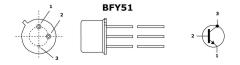
No probs, thanks for sharing.
I’ve modified your diagram to show the pinout of the 2n3055. The 2 pins under the 2n3055 are actually offset slightly to one side. It’s not clear from that previous datasheet, so try this 2n3055 datasheet. You’ll need to scroll down to page 4.
I’ve not used a multimeter to find the pinout before because I have one of these very handy component analysers. I suppose you could use the diode test mode. You should see a low resistance between base and emmitter if the +ve lead is on the base pin. It shouldn’t conduct the other way around, but don’t hold me to that, I’ve not tried it! 🙂
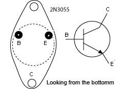
JohnnyMac:
The antiparralel inition coil setup actually seems to be more likley to blow transistors when its not loaded. If the output is loaded, then there is usually no problem. The transistors are exposed to HV spikes mostly when the circuit is being used for making sparks.
Higher powered mosfet will work, but mosfets require a higher gate/base voltage to switch them. If your DC source is 12V then this should be no problem. The gate pin of mosfets is like a capaciative load so there should be no problem driving large mosfets. If you are looking to control a motor, then I would recommend this circuit.
Problematic:
100R just means 100 Ohms. The R is often used where the decimal point would be. eg. 2R2 = 2.2 Ohms, 4k7 = 4.7k (4700) Ohms.
The way you have shown VR1 would just give the same resistance all the time. You need to use the centre pin and one outer pin.
Your question regarding the 2n3055 pinout has been answered previously. Check the post dated 3rd December 2006 4:45pm.
I am going to start rounding up parts for my project. My questions are is the second curcuit less prone to blowing transistors due to the lack of a shared ground with the high voltage?
Can higher current power Mosfets be used in this curcuit?
Is there a limit on the number of Mosfets? Possiblly with a seperate Mosfet board/unit with enough cooling could this control 80A+ electric motor, or course with protection. Mosfet ex: HUF76145P3, High Current MOSFET, N-Channel, Enhancement Mode, 75A, 30V. Ebay of course. Thanks John
The resistors are all the standard 0.6W type. The capacitor voltage rating simply need to be anything higher than your supply voltage.
All the other components are listed at the top of the page.
If you are wanting to make long sparks, then I would reccomend using a different circuit. The best one would be the Pulse controller.
You can drive almost any transformer with this circuit. How well it works will depend upon the transformer, but it will need to have a reasonably low input impeadance. A flyback may be a little more stable than an ignition coil, but if there is no load on the output you will still get some spikes induced back into your low voltage circuit.
could you use a circuit like this to power a fly back transformer. and would this transformer be a lot more stable to use on the circuit?
Bummer, I think anyone who has made an ignition coil driver (including myself) has had similar experiences. It’s always good to learn from experience though, allthough it can get expensive!
The top diagram which shows RC1 will be more stable, but it can still be blown quite easily when the output is pushed quite high. The 555 timer circuit you used has a very limited range of adjustment for pulse width (duty cycle). It stays around 50%, which is quite high and will create a lot of back EMF spikes.
The PWM signal generator has a fully adjustable duty cycle so you can adjust the power more precisley and keep it below 50%.
Obviously putting less power in, means you get less HV power out of your coil, but there is always a compromise to be made somewhere in electronics design. Running at lower power levels means that components are less likley to be destroyed, but there is still no guarantee. Making High voltage sparks from low voltage DC sources is often problematic.
There are also several other methods for protecting your components from the spikes. Have a look at Andrews posts above. This link discusses various methods for protecting against surges from inductive loads. It’s targeted for relay switching but the principles are the same.
i made the circuit posted diagram at the top and i should have listened to your advise rmc because it took two hours to build and 5 seconds to blow on my coil the tlc 555 comos timer cracked and gave off the death of circuit smoke.
dose your design handle T waves[rmc]
whats the signal generator
Jay, my last message was a reply to your question regarding using the output from a TV flyback transformer.
I expect that if you were to arc from this output to a small piece of tin, it would begin to melt the tin. The plasma temperature in the arc would be very hot, but it would draw more current from the transformer than it is designed for. The positive HV DC output is only used to create an electrostatic attraction between the moving electrons (cathode rays) and the inner surface of the screen. Making arcs (which is neccesary for the high temperatures) is effectivley a short circuit accros the transformer output.
The transformer will prrobably survive this sort of treatment if it is just intermittent, but if switching transistor is used for controling power to the coil, it will overheat and blow in a relativley short time.
Also the output of the transformer is rectified (converted to DC) by a voltage multiplier. The diodes in this may also be damaged by too much current.
You can limit the current (but thefore the temperature) drawn by your arcs by placing a large resistor in series with the output. If you don’t have such a resistor, a length of carbon may suffice.
Yes, this is a common method used for powering electrohydrodynamic thrusters known as lifters. The output from this lead is High Voltage DC.
Please be aware that the output from this terminal is highly dangerous and quite deadly. Even when switched off a capacior inside can retain a lethal amount of energy. Never put your fingers anywhere near the HV output terminal (even if the TV is unplugged). Don’t take any risks with these things, they can kill.
hi im planning on making high voltage through a fly back transformer but iam lousy with electronics. could i just disconnect the high voltage out put of the fly back from the cathode ray [tv] and use that with out any advance circuitry.
I suspect it’s likley to be one of two things…
1. Faulty 2n3055 transistor. These can fail in a wide range of ways. The most common transistor failiures cause it to latch on or off, but somtimes they can be only partially damaged, giving symptoms like you describe.
2. Faulty HV diode. In the same way as above, a diode can be just partially damged.
These sorts of intermittent or partial faults are caused by exessive voltage or current surges in the circuit.
This post may help you find more info.
Hi,
I’ve built the circuit shown on this page. when i used it worked all right. then some time later(2 weeks) it seemed like the output lost a lot of its power. I used it with a high voltage diode in series with its output to charge capacitors with a spark gap in parallel with them as to charge and discharge with pulses. now to even charge a capacitor i have to arc the high voltage to the capacitors because if i connect the wire to the capacitor the ignition coil loses all its power.
Do you have any ideas on what’s going on and how can i fix it?
Justin:
A diode is usually placed in parallel with the transistor like shown in the top schematic on this page.
While this may reduce the risk of blowing a 2n3055, it cannot guarantee full protection. There are many possible reasons for transistor failiures in inverter circuits like these.
Crispy:
Somtimes people place ignition coils in a container filled with oil. This helps prevent arcing from the ignition coils terminals.
There’s a huge numer of coil types available, ask at your local auto spares shop to see what’s available.
And another thing, I tuned the ignition coil driver to 6.6 kHz (the determined resonant frequency of the 2 coils in anti-parallel). At this point, the trace on the scope looked like an almost perfect sine wave. I then further adjusted the frequency while it was running to get the cleanest sine wave I could. There was certainly a very large voltage spike at this point, because one of the ignition coils actually started arcing from the ground terminal, through the plastic, and to the high-voltage terminal with a bright purple arc. I need to go find some better coils with thicker cases … any suggestions? These two are the oil-filled can type.
As a follow-up on the earlier discussion about the oscilloscope trace:
I was able to obtain an oscilloscope and used it to get a trace from the ignition coil generator that I made using a similar method to what you used, but I attached an antenna to the hv output a well as the oscilloscope. The trace showed something similar to your’s, but the apparent resonance was much less damped. The output waveform frequency seemed to be exactly what the input frequency was (about 1kHz) and the resonant frequency was calculated to be at approx. 6.6 kHz. Changing the antenna length on the hv side seemed to change the resonant frequency somewhat, so the antenna’s capacitance might actually have something to do with the resonance.
Looks ok as far as I can tell. I recommend you get at least one spare 393, 2n3055, and varistor, just in case 🙂
Sometimes the varistors fail catastrophically, and can thefore take out another component with it.
This happens because some varistors don’t recover very fast, so when your transistor switches on power can be shorted through the MOV causing it to blow.
Run it for a few seconds, then switch it off and check to see if your MOV (or anything else) is getting hot.
Make sure when connecting the power, duty cycle is set to low, or zero to avoid surges. Don’t turn the duty cycle up too high, it will use loads of power, but reduce the output voltage. 50% is usually suficient.
Most importantly, don’t forget, high voltage devices are very dangerous and should be treated with great care and respect. Don’t get complacent, always be very very careful.
OK, here is my final circuit diagram using your signal generator. I think I’ll build it like this right from the start. Sorry for the plagiarism of your circuit diagram, but I am a visual person and it helps me to put it all together in one diagram like this to make sure I have everything right. If you don’t find any mistakes I’ll get started right away!
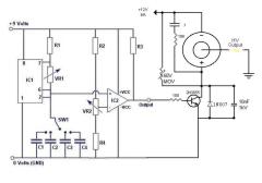
Different coils work with different frequency ranges. The larger or older ones tend not to work very efficiently at higher frequencies due to hysteresis in the large iron cores. The smaller pencil type ignition coils will work ofver a very broad range of frequencies, including ultrasonic levels, but they are usualy resin sealed and can handle less power throughput than the oil filled cylinder type. The ignition coils also have several resonant (or harmonic) frequencies which you can tune your circuit to to get maximum efficiency.
The SMPS (Switched Mode Power Supply) method can be a little more tricky with ignition coils. This is because they are effectivley autotransformers but with a very high ratio. The arcing and high voltage present at the output causes broadband RF (Radio Frequency) noise which can interfere with the correct operation of the transistors.
Anyone making this project will probably notice that the pulses to your coil are not always as regular as the signal you are sending to the transistors from the 555. This is not a major problem in this circuit, but if a bridge configuration is used, the transistors can easily be destroyed by a condition known as ‘shoot through’. The is where a pair of transistors come on together (when they should not) short circuiting the input power supply through the transistors causing them to overheat.
I think we dont need the full 555 frecuency range, so extra capacitors are not neded(or necesary) in the pwm above. Which is the frecuency range the coil should work wel to give better results? Ive built some SMPS units and the usual are 22Khz to 50Khz But for what I read I think you are tryng with 2Khz. Something about??
We can switch from 12V to 24V like in a briged audio amplifier, just using 4 transistors and a SG3525 or a 555 and a CD4013. Althoug using 4013 will force the duty cycle to 50% 🙁
What you think?
Andrew:
Your circuit seems fine to me, but I’ve used that 555 circuit before and wasn’t very impressed. It oscilates and you can adjust the frequency ok, but duty cycle control is very limited.
The DIY PWM Signal generator project is far more reliable. The addition of the LM393 comparator allows you to adjust the duty cycle between 0 and 100%.
You could always add this later if you are not satisfied with the performance of your current design.
CesarIII:
You make a good point. As mentioned above, additional components are needed for full control over duty cycle.
John:
It depends on your speaker and PSU. If you are using a 12V batery as your PSU, then each pulse will simply connect 12V directly to your speaker. I tried it with a big 8ohm speaker and it was pretty loud. I was able to tune it to the resonant frequency of my desk, causing everything on it to shake quite violently.
Justin:
Yes, the two resistors with arrows marked 10k, are variable resistors. The range of frequencies you can adjust the circuit over is still determined by your capacitor.
would a variable resistor be for fine tuning in the circuit?
Justin:
Yes, a smaller capacitor would cause higher frequncy pulses in the circuit.
If you want to change the capacitance by connecting capacitors together, connecting them in series will reduce the capacitance.
This is my finished circuit diagram for the project I am planning to build. I would appreciate it if you could look it over and tell me if I have made any mistakes. If you approve it I will order the parts and start building it! Thanks for all your help!
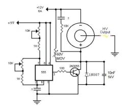
I would definatley include D1, but Jan’s method would possibly be better than the RC1 part. Varistors somtimes degrade over time if they are absorbing a lot of spikes, so including RC1 may help extend its lifetime.
The small transistor is only needed when driving lots of 2n3055’s in parralel. If you are just using one or two then you can get away with just driving 2n3055’s from the 555 output (through a 100 ohm resistor).
Sorry for asking so many questions but I just have a few more. Would the suggestions on Jan Wagner’s page be instead of or in addition to your own (D1 and RC1)? In other words should I use D1, RC1, the 10nF cap, and the MOV? Also, should I use the small transistor T1 as in your diagram or just connect the input signal to the 2n3055 as in the diagram justin posted? And would you recommend using one or two batteries? Thanks for all your help!
Justin:
The timing capacitor is usually quite small in size. I think a microwave one may be too large but theres no harm in trying it if you allready have one. Almost any capacitor will work, but its capacitance will determine the frequency of the circuit. A larger capacitor will produce lower frequency because it takes longer to charge.
The three legs on the transistor are explained in this link. You will only see 2 pins on an actual 2n3055 because the metal casing is used for the collector (+ve). You can use a 2n3055 datasheet to identify the other pins.
Andrew:
The suggestion on Jan Wagners page is certainly a good idea to help protect the transistors.
The ground terminal could be the battery negative terminal.
Thanks for your answer! I just have two more questions. I saw at a different site (http://users.tkk.fi/~jwagner/tesla/board.htm) that “A 10nF capacitor rated 1kV across the transistor collector and emitter… and a 60V varistor (MOV or VDR) across the ignition coil terminals… are useful to protect the transistor from voltage spikes that might kill it.” Would you recommend this for my Jacob’s ladder circuit? Also, if I use one coil, what should I use as the ground (the other rod of the Jacob’s ladder)? A cold water pipe? The negative terminal of the power supply or battery? Thanks in advance!
i found a 555 timer 2MHz and it was 98c very cheap. would a timing compacitor be something like a microwave compacitor or dialectric one because the shop did not have any. also the led i was refering to was or is a transistor sorry im new to this.
Andrew:
You can make a small jacobs ladder using just a single ignition coil. The size that the arc will expand to is determined by the current flowing in it.
The No. of transistors needed would depend on your coil, but you could probably just use one. Each 2n3055 can handle about 15 Amps if it is kept cool enough. Typical heatsinks for TO-3 cases are quitle large.
Using 2n3055’s can be tricky with jacobs ladders. the arcing can cause voltage spikes that exeed the thw 100V maximum of a 2n3055. Make sure you buy a few spare ones if you plan to draw arcs.
Hi, I plan to build a small Jacob’s ladder powered by an ignition coil driver, and I have a few questions. How many 2n3055’s should I use, and how big of a heatsink will I need? Also, should I use 1 or 2 coils? Thanks!
It looks like a highly damped ringing trace to me. When the DC is disconected from the coil, the magnetic field colapses and oscilates a little at some fundamental frequency of the coil.
I don’t know if you would see the same trace if it were connected by a voltage divider, but it would be good to compaare.
Any idea what is causing that dip? Is it some kind of resonant effect?
Also you might want to take a look at building a large voltage divider to get more accurate measurements than what you could get just with an antenna. I’m going to make one myself if I can get the resistors, but I calculated that a voltage divider that would use .1mA of current and would provide a 100:1 ratio would need over a thousand 400V resistors. I’m trying to see if I can find some cheap resistors rated at more than 400V.
I tested a pencil type ignition coil with 6V 50% duty cycle @ 1.85kHz.

This is a manually drawn image of the scope trace i saw from just detetcting the voltage with a small antenna about 1m away.
Oops … I think I figured out the answer to my last question … I’ll post it here for the benefit of anyone else who might want to try.
First, I’m proceeding from the assumption that the ignition coil will supply as much current as it can unless there is a load on the output with a resistance that will limit the current to less than what the ignition coil can supply.
I figured that if I connected a resistor in series with an ammeter and the ignition coil, that it would cause a voltage drop proportional to the current flowing through it (according to Ohm’s law), but the current flowing through it would be constant regardless of the resistance as long as it wouldn’t normally limit current to below the maximum that the ignition coil could supply. If the series resistor actually was limiting current, this could be calculated after the current was measured.
My multimeter can support a maximum of 600V across its leads, and when measuring current on the uA scale, has a measured resistance (by another multimeter) of approximately 110 Ohms. Estimating by the length of the spark gap, the 2 ignition coils that I have connected in anti-parallel are generating approximately 60kV. Since many of the factors here are estimates, I decided to proceed with my calculations from the standpoint that the multimeter could only handle 300V.
From these values, I calculated that a series resistor of approximately 22,000 Ohms would drop sufficient voltage so that the voltage drop across the multimeter would be approximately 300V. Using Ohm’s law, this should allow approximately 2.7A to flow through the circuit (max), so assuming that the ignition coil can’t supply that much current (which is a very reasonable assumption), it shouldn’t limit the current flowing through the multimeter.
When I connected up the circuit, it didn’t fry my multimeter (Yay!), and the multimeter measured approximately 8mA rms (although this varied a bit over time by maybe 300uA) from my two ignition coils connected in anti-parallel.
Measuring DC current, the multimeter measured very close to 0uA. This suggests that the ignition coil output has a duty cycle of almost exactly 50%, even though the signal generator that I am using is producing approximately a 75% duty cycle square wave.
I don’t have an oscilloscope, so I don’t know what the exact waveform is for the output of the ignition coil … has anyone tested this?
What would be a good, safe, semi-accurate way to measure the maximum current capable of being produced by the ignition coils (with a given tuned driver circuit)? Just hooking up the leads to an ammeter would probably cause it to arc internally because the meter’s internal resistance would be significant compared to the other resistive elements in the circuit (just the wires), but adding a resistor would decrease the current flow. Is there a good way to measure this current? Thanks.
I wish to use 4, 6 or 8 ignition coils to increase the output voltage of my system. I see that you have used four in series parallel to increase the voltage, how can one possibly use 4, 6 or 8 coils but at the same time have a single secondary output instead of the two you have in yours.
You can connect as many as you like in parallel, like in this image, but this only increases the output current and not the voltage.
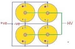
One way might be to use one ignition coil to charge a capacitor to pulse the primary of a second ignition coil. This way could make very high voltage, but I dont think the insulation in your coil would last very long.
These circuits are more of a guide than exact specifications for an ignition coil driver. This is because there are so many different types of ignition coils, each with different ratings. The application that you use the HV output for also effects how you may want to build the circuit.
The RC filter is recommended to reduce the chance of blowing the transistors, but the exact component values will depend on the frequency at which you drive your coils. Higher frequency would need smaller capacitor. The resistor just serves to limit the current.
It works by damping the oscilations in the coils, but it can therfore reduce the efficiency of the system.
If you are only operating your ignition coil driver with a stable load (like a neon light) on its output then you can get away with not using the RC filter. If you want to make sparks, jacobs ladders etc then you will need some sort of protection. I have destroyed a fair few 2n3055 transistors when driving ignition coils without protecive components. I recently added better (but less powerful) version here. you could add more MOSFETs in parralel though to make it tollerate bigger loads.
Hi,
just finished sticking together the 555 Pulse generator and am very happy with it. Now I finally obtained some ignition coils and want to test them right away. When building the Amp above, I got stuck with the RC-Filter. Why is it included in the first shematic, but left out in the second one, but again included in the big supply unit (the one with nine transistors)?? And what kind of ratings do the resistor and cap need?
The current will depend on the frequency and pulse width at which you drive a coil, but the 2n3055 transistors are rated upto 15 Amps each. The other circuit using the IRF740 is rated up to 10A
Driving a single common cylinder type ignition coil at optimum frequency/pulse width will typically draw around 5A with a load on its output.
..and what sort of current does the 12V supply need/draw for either cct? Sorry meant to ask that before.
Yes you need something to generte a square wave signal.
You can use a pre built one or there are schematics for 555 based ones here and here. You could also look at the coil driver circuit with the signal generator included
I assume you need a signal generator (i.e. 555 timer) for the first cct, where it says ‘Input Signal’?
Thanks
A new project has just been added. The DIY Pulse Controller is ideal for driving small transformers like ignition coils.
The signal apllied to the transistors can make a big difference in perfomance. It is important to use a signal generator wit good adjustability so that you can tune it to match the coils you are using.
If the pulse width (duty cycle) of frequency is not quite right you can end up drawing lots of power but only getting a tiny output from your coils. The “Signal Generator with PWM” linked above is highly reccomended for this.
24V would help, but you should try to get better output from 12V first.
When you are drawing arcs like in a jacobs ladder the output of the ignition coils is effectivley ‘shorted’ and will demand a lot of current from the PSU. Keep an eye on the temperature of your transistors when doing this.
We have been working on a new driver circuit recently and it should hopefully be ready in a few days. I’ll post a link here when it’s ready.
Hi,
I’ve built the same ignition coil driver as the one shown above. The one with 4 power transistors and 2 ignition coils. I’m only running at 12V presently and the sparks are not that dramatic. Thin blue ones at about 2cm long. My circuit is drawing about 4.5 amps though.
Is there anything I could do to create longer sparks? Would using a 24V power supply help? I’m trying to build a Jacob’s ladder.
Many Thanks
There are hundreds of differnt types of ignition coil, so I could not say for sure.
If it is the common cylinder type, there is usually a faint mark by he terminals. Also some have a different sized terminal for positive and negative. The positive terminal is usually the larger one.
If this does not help, try searching the model or type in google
How can I tell which is the negative pole on a ignition coil, I am trying to install a tachometer in my vehicle but can’t tell which is negative and which is positive.
Thank you for any help
The signal generator used for these circuits can be any square wave signal generator with the correct amplitude.
For these circuits we used a simple 555 based squarewave generator circuit. You can see the schematics at the links below.
‘Dead bug’ Signal Generator
Signal Generator with PWM
The signal generator with PWM is the more stable and versitile of the two.
What is the signal generator?