Volts, Amps and Watts
What are Volts, Amps & Watts etc?
This page details the most common terms used in electronics and often physics subjects. After reading this page you should be familiar with many of the aspects of electricity and electronics which should help you to understand man of the other pages on this site.
Electricity
Electricity is a term used to describe a physical process involving subatomic particles in materials. A battery does not hold electricity, but it is a store of energy that is used to make electrical processes work. Electricity involves the charged particles (electrons and protons) that make up ordinary matter. What we call ‘static electricity’ is a buildup or lack of electrons which are a negatively charged particle. If there is an excess of electrons on an object then it will have an overall negative charge, if electrons are removed then the object will have an overall positive charge due to the remaining protons. Notice that it is the electrons that are doing the moving around and that the protons stay where they are, fixed in the nucleus of atoms.
When the electrons are moving from one place to another we call this an electric current. In a metal the outer electrons of the atoms are ‘free’ to move around therefore if it is connected to a battery or another source of e.m.f. the electrons will be repelled from the negative terminal and attracted to the positive terminal constituting an electric current.
e.m.f. (ElectroMotive Force)
This is the force applied to charged particles such as electrons that will cause them to move. Sources of e.m.f. include chemical reactions (like in batteries) where energy is released allowing electrons to be moved around, or generators where mechanical energy is converted by using magnetic fields to influence the movement of electrons in metal wires. E.m.f. is measured in Volts (V) which is a measure of the amount of energy per unit of charge (Joules per Coulomb).
Voltage – Volts (V)
 Voltage is the measure of potential energy per unit of charge, and is measured in Volts. A voltage measurement is taken between two points separated by a dielectric or partly conductive material. A voltage can be measured even when no electrons are moving between the points as it is a measure of potential energy and will not be released until the electrons begin to flow. Because the measurement is taken between two points the voltage is also known as a potential difference (p.d.). This is because it is the difference of potential energy between the two points. For example; A measurement with a voltmeter is taken between the two points of a battery and shows a reading of 12V. Now this just means that one terminal is 12V higher than the other. It could be that one terminal is 0V and the other is +12V, or it could mean that one terminal is -6V and the other is +6V. For this situation it does not matter which it is, as either case has a voltage of 12V between the two battery terminals.
This is often useful when designing a circuit where we need a +V and a -V. Two batteries connected in sequence can be considered to have three terminals. One end is +V, the middle where they join is 0V, and the other end is considered -V. You can also use a combination of resistors with a single battery to do the same thing which is known as a voltage divider.
Current – Amps (I)
A current is the flow of charged particles (usually electrons) which is normally produced when a source of e.m.f. is applied to a conductor. The current is akin to the actual number of electrons flowing in the same direction. The amount of current flowing in a conductor is proportional to the applied voltage and the resistance of the material. For example; if a light bulb is connected to a source of e.m.f. such as a battery the current flowing through it would be calculated using I = V / R. Where I is the current, V is the voltage of the battery, and R is the resistance of the light bulb. This relationship is known as Ohms Law. You can see from this example that to double the current flowing in the bulb you would need to double the voltage applied to it.
In a conductor the electrons are flowing from the negative terminal towards the positive, but just to confuse things when talking about electrical currents we say that the current flows from positive to negative
Direct Current (DC)
This is where the current is flowing in one direction at a constant rate. A Battery causes DC to flow in circuits.
Alternating Current (AC)
This is where the current is changing with time or oscillating back and forth. A typical mains outlet causes AC to flow in a circuit. In the UK the frequency at which this current oscillates is 50Hz.
Resistance – Ohms (R)
Resistance is a measure of the restriction of the flow of current through a material. All materials except superconductors have a resistance above zero and the value is measured in Ohms (Ω). Metals have lots of ‘free’ electrons therefore they have a low resistance. In an electrical circuit it is important to use cables with a low enough resistance so that they can adequately carry the necessary current for the application. In high power applications thick wires are used because thicker wires have lower resistance.
Ohms Law and Watt’s Law
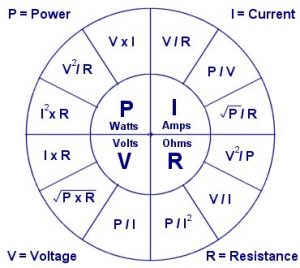
Ohms law determines the relationship between Voltage (V), Current (I), and resistance (R). The simple formula can be used to determine one unknown variable if the other two variables are known. Related to this is Watt’s Law which includes calculations for power (energy per second).
For example; If a 12V battery were connected to a 100 ohm load such as a light bulb, the current flowing in the circuit could be calculated using ohms law.
I = V/R = 12/100 = 0.12 A (120mA)
Another example would be to calculate the power drawn in the circuit.
P = V x I = 12 x 0.12 = 1.44 W
or
P = V2/R = 122/100 = 1.44 W
Power – Watts (P)
Power is a measure of the overall amount of work being done in a system in relation to time (energy used per second). In an electrical system power can be calculated by using the formula P = V I. From this you can see how the voltage and current in a system relate to the overall amount of power used. The unit of a Watt (W) is equivalent to joules per second , therefore one Watt is equal to one joule per second.
Energy – Joules (E)
Energy is a fundamental quantity that every physical system possesses. The quantity of energy available allows us to predict how much work a system could be made to do, or how much heat it can produce or absorb. For any sort of physical change energy is involved. The change can be anything such as temperature, movement, voltage, etc.
Reactance – Ohms (X)
Reactance is the measure of opposition to alternating current flow in a circuit. The opposition is caused by the effect of an inductor or capacitor. In a coil of wire (inductor) in an AC circuit the changing magnetic field produced by the current has the effect of inducing a voltage of opposite polarity to the polarity at that moment in time. This is known as back e.m.f.
Impedance – Ohms (Z)
Impedance is similar to resistance but it is used to describe the total amount of opposition a circuit offers to the flow of alternating current. It is simply a combination of the resistance and the reactance of a circuit. With inductors (wire coils) the impedance is higher at higer frequencies whereas with capacitors the impedance is lower at higher frequencies.
Inductance – Henries (L)
Inductance is the measure of how well a coil (inductor) or conductor is able to produce a magnetic field from a given current. Inductance is equivalent to the magnetic flux divided by the electrical current. A Coil of wire having a high value of inductance would typically be made from a large number of turns of wire. The effect of the magnetic field produced by the inductor has the effect of making a reactance to the change of current flowing in the coil. If a DC current is passing through a coil there will be a stable magnetic field around it. If the source of e.m.f. is suddenly removed the magnetic filed will collapse inducing a current back into the coil. In an AC circuit this has the effect of altering the phase relationship between the voltage and current.
Self Inductance is simply the property of a coil or inductor. It’s called self inductance because each turn of wire in the same solenoid will induce a current in its self (and the nearby ones) as the field around it changes.
Mutual Inductance is the total inductance produce by the interaction of two or more inductors. As the field around one coil or inductor changes, it effects other nearby inductors. The the strength of the effect the coils have on each other is known as coupling. The formulae below are used to calculate the mutual inductance produced between two solenoids that are magnetically coupled.
M = µ0N1N2lπr2= (L1L2)1/2
M = k(L1L2)1/2
Induction
Induction is a term used to describe how electromagnetic effects are copied from one object to another. When a charge or current in an object is changed, we say that it induces a charge or current in an object to which it is somehow coupled. Although the words ‘inductor‘ and ‘inductance‘ are mostly used when describing magnetic fields and solenoids, the words ‘induction’ and ‘induce(ed)’ are used to describe both electric and magnetic effects. For example:
Magnetic induction – The output (secondary coil) of a transformer is connected to a light bulb or LED, while the input (primary coil) is repeatedly connected and disconnected from a battery. As the battery is connected or disconnected, there is an abrupt change in the magnetic field created by the current in the primary coil. This field also surrounds (is coupled with) the secondary coil and therefore when the primary current changes a current is induced into the secondary coil causing the LED to briefly light up.
Electric Induction – A metallic ball is fixed centrally between two metal plates. All three objects are separated by several cm of air. If a voltage is applied to the plates so that one plate becomes more negative than the other there will be an electric field between the plates. The metallic ball has ‘free’ electrons which can be moved around quite easily (this is why metals conduct). Electrons are negatively charged and will therefore be pushed away from the negative plate (opposites attract, like poles repel). This causes there to be more electrons (therefore more negative charge) one one side of the ball than the other. Even though nothing touched the ball it now has a positive and a negative side, and we call this a dipole. More specifically here, the ball has an induced dipole moment.
Capacitance – Farads (C)
This is the measure of how well conductor – insulator barrier is able to store energy. It is widely stated that a capacitor stores charge, but this is simply not true, the total charge inside a capacitor is always the same. The capacitor stores energy by keeping separate regions of different levels of charge. The attractive force between the areas of opposite charge in a capacitor is used as the energy source to cause a current to flow when its terminals are attached to an external circuit.
Charge – Coulombs (Q)
Charge is a property possessed by particles and physical objects. In most objects the overall charge is zero but it can be made to become positive or negatively charged by an amount measured in coulombs. A single electron carries a negative charge of about 1.6 × 10⁻¹⁹coulombs. An object is considered charged when it has either an excess or a deficit of electrons therefore giving the object an overall positive or negative charge. A capacitor is considered as charged when the charge on its plates is separated within the device, but the overall charge remains constant.
Coupling
This term is used to describe the amount of electromagnetic linkage between two conductors or coils. As the field around one object is changed, it will cause a similar change in other nearby objects. The strength of this change is determined by the coupling coefficient. Moving two objects closer together would have the effect of increasing the effect they have on each other, and therefore the increasing coupling coefficient (k). The value ‘k’ is between 0 and 1, and is simply used as a multiplier to represent the amount of coupling between the objects. In high speed circuits it is important to pay attention to coupling between various tracks on a PCB, as unwanted coupling will interfere with signals causing data to become corrupt.
Capacitive coupling refers to the coupling between capacitors, or conductors (usually metal) separated by a dielectric (insulator). The coupling occurs because as the electric field around one object changes, it induces a relative change in nearby conductors. The plates in a capacitor are tightly coupled which is why they can pass alternating currents even though there is a dielectric barrier in the circuit.
Magnetic coupling is used to describe the linkage between two current carrying conductors such as solenoids or transformer windings. A changing current in one coil of wire will cause a changing current in a nearby coil. The strength of the change is determined by the coupling coefficient. In a transformer the two separate coils (primary and secondary) are tightly coupled by wrapping them around the same ferrous core.
Frequency – Hertz (F)
Frequency is the measure of rate of change and is given in Hertz (Hz). One Hz is equivalent to one full cycle per second. The time taken to complete one full cycle is called the period.
Phase – Radians (Θ)
Phase is the measure of the difference in position of two waves or cycles and is measured by the the equivalent angle of a wave. The angle is usually given in radians but it is shown as degrees in the diagram for simplicity.
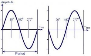 Here you can see diagrams representing two waves that have a phase difference of 180 degrees.
A full cycle of a wave is equivalent to a rotation of 360 degrees or 2π Radians.
Pulse Width Modulation (PWM)
P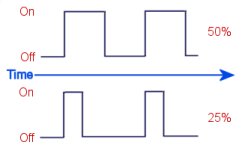 WM is a method controlling the ratio of on to off time in a square wave signal. This is commonly used for controlling the average amount of power flowing to a device, or to alter the position of a servo motor. The ratio of on to off time is referred to as duty or duty cycle and is expressed as a percentage. For equal on and off time the duty is 50%, for fully on it is 100% and fully off is 0%. You can find a schematic for a pulse width modulation circuit on the DIY Power Pulse Controller page. We also have a selection of PWM Circuits for sale.
Anode and Cathode
These are terms used to describe electrodes or electrical terminals in a device. The Anode represents the positive terminal whilst the cathode represents negative. The terminals of diodes are often named anode and cathode.
Dielectric
This is another name for an insulating or non conductive material. The material between the plates of a capacitor is a dielectric, and the ‘dielectric constant’ of this material determines the effectiveness of the capacitor.
Ionisation
Ionisation is a process which occurs when atoms or molecules are highly energised. When an atom has a non-neutral overall charge is is called an ion. This ion can be either positive or negatively charged. During electrolysis, ions are formed which move between the electrodes in a solution and then stop at the electrodes when they are neutralised,
Also high voltage electricity is used to ionise gasses so that they will become a plasma. When exposed to high enough voltage, some electrons can be removed from the atoms so that the atom is positively charged. When the electrons are being ripped away and then pulled back into other atoms, light is released. We make use of this phenomenon in neon lights.
Polarity & Dipoles
Polarity is used to describe the orientation of electric or magnetic fields. The word ‘dipole’ is used to describe objects which have two ends with opposite charges or magnetic fields. A typical bar magnet is a dipole because it has a North and a South end. If this magnet is turned upside down so that the N and S have swapped places, it is now oriented with the opposite polarity. This works in the exact same way for a battery. If the wires to a battery from a circuit are swapped over, then the polarity has been reversed.
Ferrous
This term is used to describe materials with Iron (Fe) like properties.
Specifically it is the magnetic properties of iron that are being referred
to. Ferrous materials can be magnetised and are attracted to magnets. Ferrous materials also exhibit hysteresis.
Hysteresis
This term is used to describe an effect seen in ferrous materials, and is also used to describe a sort of memory effect in analogue circuits. In ferrous materials hysteresis is the ‘magnetic memory’ of the material. If a solenoid is energised around a piece of Iron, a magnetic field will be induced into the metal and therefore increasing the overall field strength, if the polarity of the solenoid is reversed, then it must overcome the magnetic field of the iron which still rests partially in the previous polarity. In a transformer this is an unwanted property as energy is wasted by having to repeatedly overcome the magnetisation of the material. The typical way of representing this property of a material is to draw a graph known as a BH curve.
In an electronic circuit we can add an electronic form of hysteresis to help stabilize an unwanted or spurious oscillation. This is commonly used in a thermostat circuit so that a device isn’t randomly switched on and off when the temperature is at the threshold level. It is basically a way of separating the ‘on temperature’ and the ‘off temperature’. e.g. A heater comes on when the temperature is below 15 Celsius, and off again at 20 Celsius.
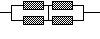
Series & Parallel Circuits
When components are connected in series they are connected end to end in sequence. This causes the voltage to be shared between the components whilst the current through each is the same.
In a a parallel circuit the components are connected with all their similar terminals connected together (e.g. all positive terminals together and all negative terminals together.) Each component will have the same voltage across its terminals.
Analogue Electronics
This term is used to describe circuits which involve mostly varying currents and voltages like you would find in a radio or amplifier. Analogue systems have a ‘fuzzy’ design as component tolerance can vary. There is often a lot of tuning and adjusting after a circuit has been made. An analogue circuit can be from anything from a simple amplifier to an old TV or radio.
Digital Electronics
These circuits are usually based in transistors and logic devices. Digital circuits can be designed to produce exact and repeatable results. They often use computer chips or microcontrollers for performing calculations. Memory can also be used to allow a sequence of events to be recorded or triggered.
Next Page: Electronic Components
Previous Page: Learn Electronics
52 Comments
Leave a Reply
You must be logged in to post a comment.
The power flowing through the computer varies between different computers and will also vary depending on hat the computer is doing..
Mains input in the UK is 220V @ 50Hz. A typical PC would use about 350W when running which would mean it is pulling about 1.6A.
I was wondering How many watts volts amps and hertz are in a computer?
You can’t work it out from the information you provided. You also need to know either the power (watts) or the impedance/resistance (ohms).
I have a question dealing with hertz and amps. My refrigerator is 115V/60 Hz. Is this equal to or less than 1.5 amps?
Thank you
simplycyndeee@yahoo.com
Chemical reactions provide the energy to force electrons around a circuit.
What in the construction of a battery causes its potential difference so that we can measure it in voltage?
Type your message here
Excellent idea using the wheel for your ohms law calcs. I wrote a simple prog for calculating the tricky ones eg sqr root and squared
Tom,
Yes, if you use RMS voltage. It gives you an average power because AC is constantly changing.
Ken,
What circuit?
What formula or formulas would be used to find the value of resistor R1 in order to supply the proper voltage to this circuit.
Using P=V^2/R results in an answer about 10 times what I expected. Is this formula valid for AC?
Thanks
A resistor does not provide isolation, so I think it would depend on your circuit. What circuit is it for?
what is the purpose of an isolation resistor?
It is not a property of the capacitor, but one of the dielectric. You just need to find the breakdown voltage per mm thickness of your dielectric material. These figures obtained experimentally so you should just google for the value.
Got another one for you. How would you calculate the voltage rating for a parallel plate capacitor?
Yes what you suggest is correct.
Sorry, typo now corrected.
I am a bit confused by your last comment. Did you mean that since the energy is constant, increasing c must cause v to decrease? Based on the equation you gave that would make sense.
Moving the plates together would decrease the voltage.
The laws of conservation of energy must apply. The total energy stored in the capacitor should be the same before and after you move the plates.
The capacitance increases as you bring the plates together. The energy is calculated as 1/2 cv2 therefore if the energy is constant, increasing c (capacitance) must cause v (voltage) to decrease.
suppose i have a paralle plate capacitor. if i have a constant voltage across it and slowly bring the plates closer together shouldn’t i see a slight increase in voltage until the discharge? If so, what possible explanations are there for me not seeing that voltage change?
I don’t really understand what you are asking. The diameter of wire you need is related to the current that you want to flow through them. Since your application is audio, the current will vary with time. You need to calculate an RMS or average value.
I have a stereo question, I have 2 500k capacitors, with two 12V batterys; they ushally read between 14.06 V and 11.08; when I have my stereo playing at different volumes. I have a total of 3760 Watts of power with all my amps at peak. What I dont understand is how should I find the total “draw” of power from the batterys to the capacitors, how they store power, and get the power to the amplifiers. Whats the difference in voltage mean and relate to power drawn? How can I increase charge related to wire size?
Madhur,
You also need to know the current the the device is rated for or the maximum current you want to flow. With that, you cam then use ohms law.
dam1914,
Yes those values are correct.
Nick,
Yes
Say I connect 4 resistors together so that they are 2 parralel lines of 2 series resistors.
If they are all of equal value can i run 4x(or nearly) the wattage that I could through just 1? with the same resitance as 1?
I’m trying to compute the amps my standby generator (used) can safely support. It generates 15kw, and as I understand it, that means I can draw 136 amps if it’s 110v, or 68 if it’s 220v. Have I got it right?
How can we calculate the resistance required if input voltage is given and required voltage is given? Eg. :- Input voltage is 240V and required voltage is 1.5V Without using stepdown transformer.
To the person who asked why “I” is used for current. I recall it stands for Intensity. E stands for Electromotive force, R resistance, P+ power
Wire is often made using extrusion or stretching techniques. This naturally forms round or cilindrical strands. It is just the ease of manufacturing that makes most wires this way. Other shapes of wire are available for those who have a specific need for it.
i would like to ask why wire is circle and not rectangular for example.
Almost. Power measured in watts is equivalent to the energy in joules delivered each second. If a device is rated for 200W it means it can supply 200 joules every second.
Power = Energy / Time
If I understand correctly Joules is the Enerigy potential in a system whereas Watts is the Power used by the energy to perform the work of the system. Correct? It is stated that one Joule is equal to one Watt so if I have equipment rated at 200 Watts it is also rqated at 200 Joules?
It would be tripled. You just add the values together when they are connected in parallel.
what happens if I put 3 capacitors in parallel? earlier, you said that putting 2 of them in parallel would double the capacitance, but what if a third one is added on? Is the capacitance tripled instead of doubled? I’m just a little bit confused. Thank you again for all your help!
Der Strom
Thanks! that helps a lot!!!
Connecting two identical capacitors in series will double the voltage rating, but half the capacitance. If they are placed in parallel the voltage rating remains the same but the capacitance is doubled. This page gives more info about connecting capacitors together.
Is there a way to put two capacitors together to increase the voltage rating, but keep the capacitance the same as with one?
example: If I have my 6.8nF capacitor, but it’s only rated for 15 kv. could I put two of them together to get the 30,000 volts I need and keep the 6.8nF?
It doesn’t seem to make sense that that would work, but I thought I’d ask anyway.
Oh! Sorry! Yes, it is really 17.5kv. My mistake.
In your original post you stated the voltage as 17kV. Here you are using 17.5kV.
it was in posts 2443 +2447 (2443 was my question)
Thats fine. Did I just estimate 765? Can you give me the post number?
I multiplied Vxl (V=17,500, l=.045) and got 787.5 watts.
Show me how you work it out
Earlier, I had asked you how much power my OBIT put out, you said it was about 765 watts, but after recalculating a few times, I kept getting a result of 787.5 watts. was I using the wrong formula?
You must also consider time. Power is calculated by volts x amps. This gives you the energy per second.
For example;
If you connect a 12 ohm resistor between the terminals of a 12 Volt battery for 1 second, 12 joules of energy will be taken from the battery and dissipated as heat in the resistor.
So for 1 amp, 12V for 1 second, the energy is 12 joules.
Is there a way that I can find the energy (in joules) just from knowing the voltage and amperage?
The “I” in Ohm’s Law stands for the word INTENSITY. The intensity of current flow is measured in Amps.
The capacitance will not change. Adding more charge to one plate will push the same amount of charge out of the other plate (assuming it is in a circuit and has somewhere to go). This will increase the overall amount of energy stored in the capacitor but the total amount of charge in the whole capacitor will remain the same.
in parrallel plate capacitor, if I add some more charge to one plate of the capacitor what would happen to the capacitcance?
There is no direct conversion. You need more variables to complete a calculation. See the section on Ohms / Watts law for the formulae.
You would be best asking at your local camera dealers, or post a message in a photography forum.
I’m in need of information regarding the conversion of watts to votage, if that is even possible. I purchased a safe sync for my camera that will protect it up to 400 voltage. The strobe lights have a 2400 watt capacity. I’m loss and I don’t want to fry my camera. Please help.
When a current flows through a resistor there is a voltage drop across it. This voltage drop causes energy to be dissipated through the resistor as heat.
The power rating of a resistor refers to how much heat it can safely dissipate without breaking down or melting.
The power dissipated in a resistor is proportional to the square of the current flowing through it and is calculated using the following formula.
P = I2 x R
Power (Watts) = Current (Amps) squared times Resistance (Ohms)
Question; why are resistors given a “watt” value when they are measured in ohms of resistence.
‘I’ is just the letter used to represent current when writing fomulae. It does not represent anyones name. The name associated with current is ‘Ampere’. This is a persons surname but it is usually shortened to ‘amps’ which is the unit of current (coulombs per second).
I would appreciate if you could explain me how ‘I’ has been used to represent current. Does it stand for someones name?