
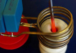
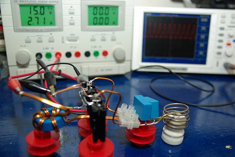
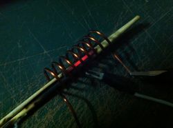
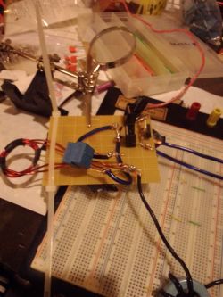
This great little project demonstrates the principles of high frequency magnetic induction and how to make an induction heater. The circuit is very simple to build and only uses a few common components. With the induction coil shown here the circuit draws about 5A from a 15V supply when a screwdriver tip is heated. It takes approximately 30 second for the tip of the screwdriver to become red hot!
The control circuit uses a method known as ZVS (zero voltage switching) to activate the transistors which allows for an efficient transfer of power. In the circuit you see here, the transistors barely get warm due to the ZVS method. Another great thing about this device is that it is a self resonant system and will automatically run at the resonant frequency of the attached coil and capacitor. If you want to save some time, we have an induction heater circuit available in our shop. You might still want to read this article though for some good tips on getting your system working well.
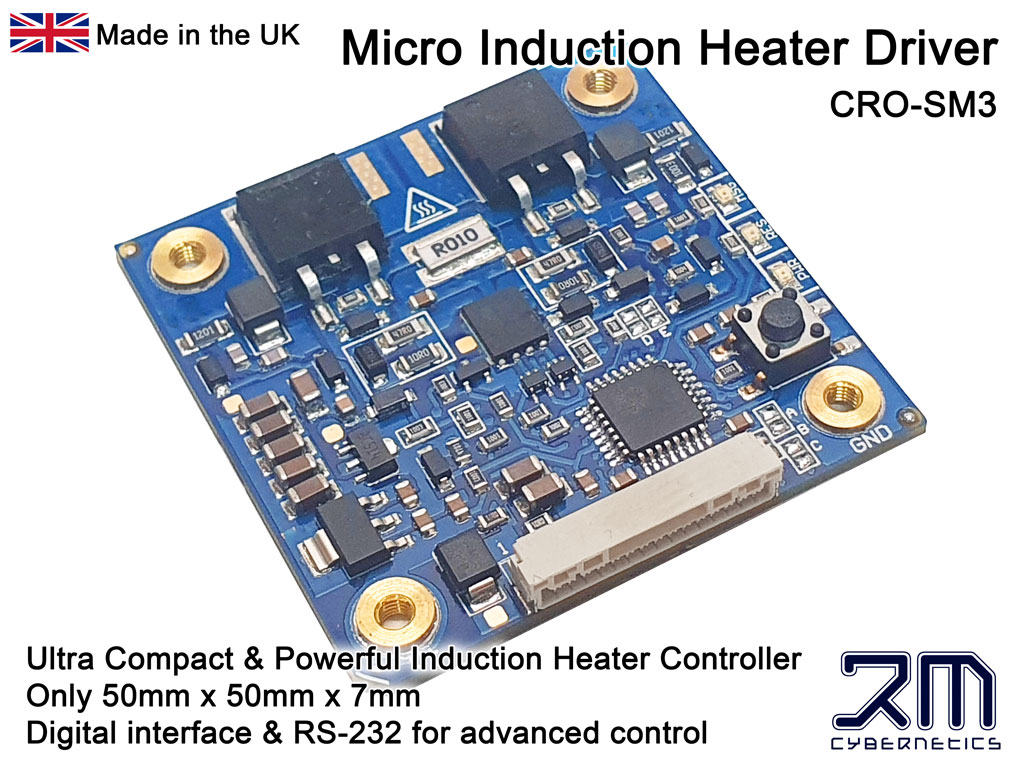
Induction Heater Circuit – CRO-SM3
Price range: $159.89 through $177.21
Select options
This product has multiple variants. The options may be chosen on the product page
Induction Heater Coil
$86.59
Select options
This product has multiple variants. The options may be chosen on the product page
 How Does Induction Heating Work?
When a magnetic field changes near a metal or other conductive object, a flow of current (known as an eddy current) will be induced in the material and will generate heat. The heat generated is proportional to the current squared multiplied by the resistance of the material. The effects of induction are used in transformers for converting voltages in all sorts of appliances. Most transformers have a metallic core and will therefore have eddy currents induced into them when in use. Transformer designers use different techniques to prevent this as the heating is just wasted energy. In this project we will directly make use of this heating effect and try to maximise the heating effect produced by the eddy currents.
If we apply a continuously changing current to a coil of wire, we will have a continuously changing magnetic field within it. At higher frequencies the induction effect is quite strong and will tend to concentrate on the surface of the material being heated due to the skin effect. Typical induction heaters use frequencies from 10kHz to 1MHz.
![]() DANGER: Very high temperatures can be generated with this device!
DANGER: Very high temperatures can be generated with this device!
 The Circuit
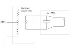
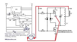
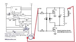
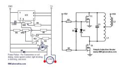
The circuit used is a type of collector resonance Royer oscillator which has the advantages of simplicity and self resonant operation. A very similar circuit is used in common inverter circuits used for powering fluorescent lighting such as LCD backlights. They drive a centre tapped transformer which steps up the voltage to around 800V for powering the lights. In this DIY induction heater circuit the transformer consists of the work coil and the object to be heated.
The main disadvantage of this circuit is that a centre tapped coil is needed which can be a little more tricky to wind than a common solenoid. The centre tapped coil is needed so that we can create an AC field from a single DC supply and just two N-type transistors. The centre of the coil is connected to the positive supply and then each end of the coil is alternately connected to ground by the transistors so that the current will flow back and forth in both directions.
The amount of current drawn from the supply will vary with the temperature and size of the object being heated.
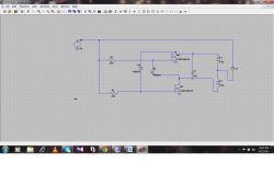
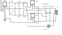
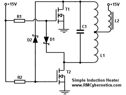 From this schematic of the induction heater you can see how simple it really is. Just a few basic components are all that is needed for creating a working induction heater device.
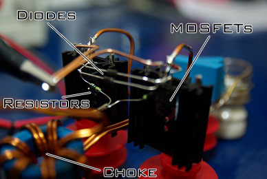
R1 and R2 are standard 240 ohm, 0.6W resistors. The value of these resistors will determine how quickly the MOSFETs can turn on, and should be a reasonably low value. They should not be too small though, as the resistor will be pulled to ground via the diode when the opposite transistor switches on.
The diodes D1 and D2 are used to discharge the MOSFET gates. They should be diodes with a low forward voltage drop so that the gate will be well discharged and the MOSFET fully off when the other is on. Schottky diodes such as the 1N5819 are recommended as they have low voltage drop and high speed. The voltage rating of the diodes must be sufficient to withstand the the voltage rise in the resonant circuit. In this project the voltage rose to as much as 70V.
The transistors T1 and T2 are 100V 35A MOSFETs (STP30NF10). They were mounted on heatsinks for this project, but they barely got warm when running at the power levels shown here. These MOSFETs were chosen due to having a low drain-source resistance and fast response times.
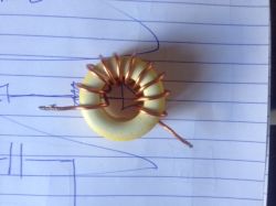
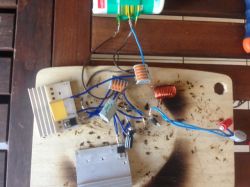
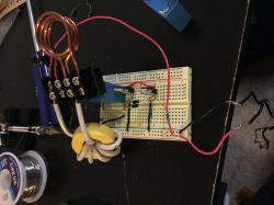
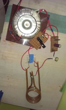
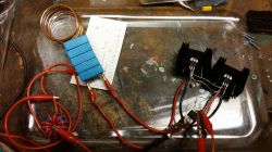
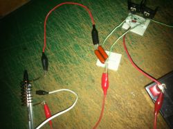
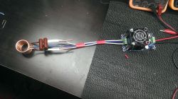
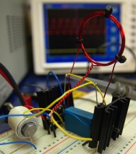 The inductor L2 is used as a choke for keeping the high frequency oscillations out of the power supply, and to limit current to acceptable levels. The value of inductance should be quite large (ours was about 2mH), but also must be made with thick enough wire for carrying all the supply current. If there is no choke used, or it has too little inductance, the circuit might fail to oscillate. The exact inductance value needed will vary with the PSU used and your coil setup. You may need to experiment before you get a good result. The one shown here was made by winding about 8 turns of 2mm thick magnet wire on a toroidal ferrite core. As an alternative you can simply wind wire onto a large bolt but you will need many more turns of wire to get the same inductance as from a toroidal ferrite core. You can see an example of this in the photo on the left. In the bottom left corner you can see a bolt wrapped with many turns of equipment wire. This setup on the breadboard was used at low power for testing. For more power it was necessary to use thicker wiring and to solder everything together.
As there were so few components involved, we soldered all the connections directly and did not use a PCB. This was also useful for making the connections for the high current parts as thick wire could be directly soldered to the transistor terminals. In hindsight it might have been better to connect the induction coil by screwing it directly to the heatsinks on the MOSFETs. This is because the metal body of the transistors is also the collector terminal, and the heatsinks could help keep the coil cooler.
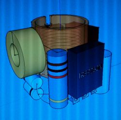
The capacitor C1 and inductor L1 form the resonant tank circuit of the induction heater. These must be able to withstand large currents and temperatures. We used some 330nF polypropylene capacitors. More detail on these components is shown below.
 The Induction Coil and Capacitor
The coil must be made of thick wire or pipe as there will be large currents flowing in it. Copper pipe works well as the high frequency currents will mostly flow on the outer parts anyway. You can also pump cold water through the pipe to keep it cool.
A capacitor must be connected parallel to the work coil to create a resonant tank circuit. The combination of inductance and capacitance will have a specific resonant frequency at which the control circuit will automatically operate. The coil-capacitor combination used here resonated at around 200kHz.
It is important to use good quality capacitors that can withstand large currents and the heat dissipated within them otherwise they would soon fail and destroy your drive circuit. They must also be placed reasonably close to the work coil and using thick wire or pipe. Most of the current will be flowing between the coil and capacitor so this wire must be thickest. The wires linking to the circuit and power supply can be slightly thinner if desired.
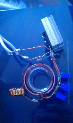
This coil here was made from 2mm diameter brass pipe. It was simple to wind and easy to solder to, but it would soon start to deform due to excess heating. The turns would then touch, shorting out and making it less effective. Since the control circuit stayed relatively cool during use, it seemed that this could be made to work at higher power levels but it would be necessary to use thicker pipe or to water cool it. Next the setup was improved to tolerate a higher power level…


 Ceramic Standoff
 Current Meter
 12V 15A Power Supply
 12V Water Pump
 Choke
Choke Cooling Radiator
 35A 100V Transistors
 Silicone Pipe
 TO-220 Heatsink
 240 ohm Resistors
 Fast Diodes
 Polypropelene Capacitors
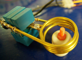 Pushing it Further
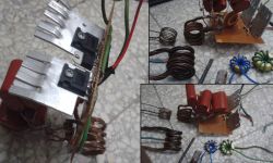
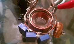
The main limitation of the setup above was that the work coil would get very hot after a short time due to the large currents. In order to have larger currents for a longer time, we made another coil using thicker brass tubing so that water could be pumped through when it was running. The thicker pipe was harder to bend, especially at the centre tapping point. It was necessary to fill the pipe with fine sand before bending it as this prevents it from pinching at the sharp bends. It was then cleared out using compressed air.
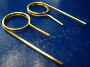 The induction coil was made in two halves as shown here. They were then soldered together and a small piece of pvc pipe was used to connect the central pipes so that water could flow through the whole coil.
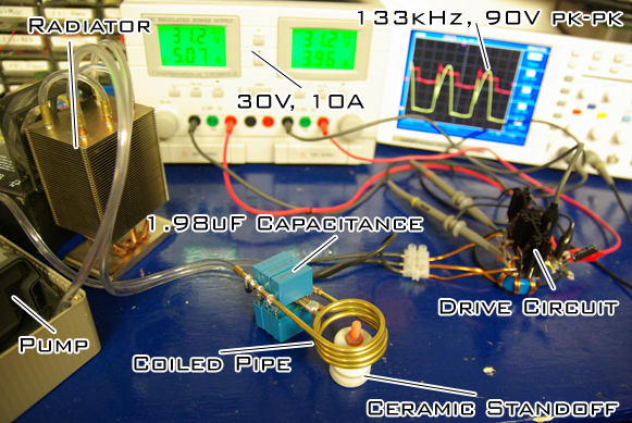
Less turns were used in this coil so that it would have a lower impedance and therefore sustain higher currents. The capacitance was also increased so that the resonant frequency would be lower. A total of six 330nF capacitors were used to give a total capacitance of 1.98uF.
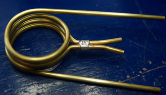 The cables connecting to the coil were just soldered onto the pipe near the ends, just leaving room for fitting some PVC pipe.
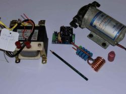
It is possible to cool this coil simply by feeding water through directly from the tap but it is better to use a pump and radiator to remove the heat. For this, an old fish tank pump was placed in a box of water and a pipe fitted the outlet nozzle. This pipe fed to a modified computer CPU cooler which used three heat-pipes to move the heat.
The cooler was converted into a radiator by cutting the ends off the heat pipes and then linking them with PCV pipes to the the water would flow through all 3 heatpipes before exiting and going back to the pump.
If you do cut some heatpipes yourself, make sure to do it in a well ventilated area, and not indoors as they contain volatile solvents that can be toxic to breathe. You should also wear protective gloves to prevent skin contact.
 This modified CPU cooler was very effective as a radiator and allowed the water to remain quite cool.
Other modifications needed were to replace the the diodes D1 and D2 with ones rated for higher voltages. We used the common 1N4007 diodes. This was because with the increased current there was a larger voltage rise in the resonant circuit. You can see in the image here that the peak voltage was 90V (yellow scope trace) which is also very close to the 100V rating of the transistors.
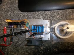
The PSU used was set to 30V so it was also necessary to feed the voltage to the transistor gates via a 12V voltage regulator. When no metal was inside the work coil, it would draw about 7A from the supply. When the bolt in the photo was added, this went up to 10A and then gradually dropped again as it heated up beyond curie temperature. It would certainly go over 10A with larger objects, but the PSU used has a 10A limit. You can find a suitable a 24V, 15A PSU in our online shop.
The bolt you can see glowing red hot in the photo took about 30 seconds to reach maximum temperature. The screwdriver in the first image could now be heated red hot in about 5 seconds.
In order to go to higher power than this, it would be necessary to use different capacitors or a larger array of them so that the current was more distributed between them. This is because the large currents flowing and high frequencies used would heat the capacitors significantly. After about 5 minutes of use at this power level the DIY induction heater needed to be switched off so that they could cool down. It would also be necessary to use a different pair of transistors so that they could withstand the larger voltage rises.
In all this project was quite satisfying as it produced a good result from just a simple and inexpensive circuit. As it is, it could be useful for hardening steel, or for soldering small parts. If you decide to make your own induction heater project, please post your photos below. Please read through the other comments before making your own as it could save you time later on.
If you wish to simulate this project for testing different inductance values or transistor choices, please download LTSpice and run this DIY Induction Heater Simulation (Right click, Save as)
How hot will it get?
It is difficult to say how hot you will be able to get something as there are many parameters to consider. Different materials will react differently to induction heating and their shape and size will affect how the heat up or shed heat to the atmosphere.
You can get a rough idea using some basic calculations with the formula below, or if you prefer, we made a handy Heater Power Calculator that can work it out for you. This form includes materials (like water) that can not be directly heating using induction heaters, but it is still useful if you are trying to work out for example the power needed for heating a pan of water using a induction heater.
How hot will something get?
How long will it take for something to reach a specific temperature?
How much heater power is needed to heat something to a certain temperature?
EXAMPLE: How hot will 20g of Steel get in 30 seconds when heated with a 300W heater? (assuming 100W is lost to the surroundings)
Formulae:
Q = m x Cp x ΔT
ΔT = Q ÷ m ÷ Cp
Working:
(300W – 100W) x 30s = 6000J
6000J ÷ 20g ÷ 0.466J/g°C = 643.78°C
Result:
20g of Steel will increase in temperature by 643.78°C when heated with a 300W heater for 30 second(s).
Troubleshooting
If you have trouble getting this working, here are a few tips to help troubleshoot your home made induction heater project….
PSU (Power Supply)
If your PSU is unable to deliver a large surge of current when the induction heater is powered on, then it will fail to oscillate. The voltage from the supply will drop during that moment (although the PSU may not display this) and this will prevent the transistors from switching correctly. To help with this problem, you can place several large electrolytic capacitors in parallel with the supply. When charged they will be able to deliver a large surge current to your circuit. A good powerful supply would be our 24V 15A DC PSU.
Choke (inductor L2)
This limits the power to your induction heater. If yours is not oscillating, then you may need more inductance to prevent voltage drop in your PSU. You will need to experiment with how much inductance you need. Better to have too much, than too little as this will only limit the power of the heater. Too little may mean it wont work at all. If your inductor core is too small, high current will saturate it and cause too much current to flow and potentially damage your circuit.
Wiring
Keep the connecting wires short to reduce stray inductance and interference. Long wires add unwanted resistance and inductance to the circuit and can result in unwanted oscillations or poor performance. Our 30A power cable is well suited to this.
Components
The transistors chosen must have a low voltage drop / on-state resistance otherwise they will overheat, or even prevent the system from oscillating. IGBTs will proabbaly not work, but most MOSFETs with similar ratings should be OK. The capacitors must have a low ESR (resistance) and ESL (inductance) so they can tolerate the high current and temperatures. The diodes should also have a low forward voltage drop so that the transistors switch off correctly. They should also be fast enough to work at the resonant frequency of your induction heater.
Powering it up
When switching it on, do not have metal within the heating coil. This can lead to larger current surges which could prevent the oscillation from starting as mentioned above. Also do not try to heat large amounts of metal. This project is only suitable for small induction heaters. If you want to control or gradually turn up the power, you can use one of our power pulse modulator circuits. See post 5108 below for details.
Brain
You will need a brain that functions reasonably well to make this project safely. It can be very dangerous to build an induction heater, so if you are new to electronics, you should get someone to help you make it. Approach things logically; If it is not working, check the components used are not faulty, check connections are correct, read this whole article and all the comments, search Google if you do not understand any of the terms, or read through our Learn Electronics section. Remember: Hot things will burn you and can set things on fire; Electricity can electrocute you and also cause fire. Put safety first.
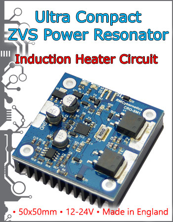 Induction Heater Circuit available to buy
A fully assembled and tested Induction heater circuit is now available to buy from our shop. This circuit is a compact and efficient version of the circuit in this article.
The circuit has in input for enable/disable of the power output so that it can be modulated by a PWM circuit for power control.
You can also buy the induction coil or parts such as copper pipe, litz wire, water cooling, capactiors, 24V PSU and more.


I have a cheap induction heater that has a knob for “output current” is this referring to the current in the coil or in the workpiece itself?
I think you need to ask the company that makes/sells it, or refer to the manual.
Hi,
I have created a circuit using the CRO-SM2, the coil kit with 4 turns coil about 45 mm diameter, Oled display and 5A Choke. I am heating a 10 mm rod, lenght 100 mm. The circuit works fine, but I would like to reduce the heating power significantly. Now I would need to switch the circuit on for less than a few percent of the time to heat the rod to a constant temperature between approx. 80 deg.C. Could you advise me how to achieve this. Does the L2 copper coil need more turns?
Thanks,
G.J. Scheers
Hello. The best way to control heating power is by adjusting the voltage supply to the choke. The cuicuit needs 12V, but you can use a seperate supply for the heating coil (they must share a common GND). One way is to use a DC-DC convertor to step the voltage down if you do not have a suitable PSU.
More turns MAY reduce heating, but it depends on magnetic coupling to the workpiece which may even increase the heating effect.
Hi would it be possible to use a bifilar coil to
to dissipate the current and give a lower heat
generation in the coil?.thanks
Hello, the project is very interesting so I built guiding me in his scheme to try. I have done some tests and after 5 minutes of continuous work the consumption current in the load decreases. I think it’s because the resonant tank gets too hot and change its characteristics or physical properties.
I wonder if the induction heater can operate for several hours without losing their efficiency , thanks.
Hi is it posible to build an induction heater at larger scale I need to heat up a metal plate about 3/16 thick by 8 feet wide by 22 feet long? If yes would you be able to design it and post it here? Thank you for your help
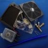
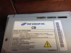
I am trying to build this circuit for a high school science project and can use a little help. To keep it simple I bought The CRO-SM1 Heater Driver Circuit, the 24V 15A DC PSU, and the prebuilt Induction Heater Coil (CT-400), water pump, and choke coil from an old microwave (picture attached). Basically everything in Figure 3 of the CRO-SM1 manual.
I have gotten to the point where I have everything connected pump working, etc. and when I initially turn the switch on at the switch the power and active LED’s come on initially. However when I connect the choke to the power supply the LED’s turn off within a half second.
I went through the CRO-SM1 documentation and shortened the connection to the work coil to 4cm (12guage wire) thinking that was the problem but have the same results. My only unknown is the choke coil but I don’t have an inductance meter but find it hard to believe that is the problem.
Do you have any suggestions?
I built my circuit twice.
The first time I used the IRF540N (similar to stp30nf10), five capacitors of 470 nF (totaling 2.35uF), two diodes 1N4007, two resistors of 220ohms, an inductor of 2.3mH. The circuit one heated and worked screwdriver for about 3 minutes at a voltage of 8V and 4A current, but the capacitors burned.
I did the exchange of ALL the components, but I used MOSFETS FQP33N10 (like also with STP30NF10) and twelve capacitor 470nF (totaling 5.64uF) to support higher currents. But the circuit does not work, the MOSFETS heat up and is apparently toggling, but there is no temperature increase in capacitors and or the key used in the work coil.
What should I do? The problem may be attached to the resonant frequency?
Thank you!
photo1: 1° circuit
photo2: 2° circuit
photo3: drive
Is it possible to use this concept to heat a 44 quart stock pot? It will be used in soap and lotion production.
I need to design and build a very small, portable induction heater. the best way to describe my final application is that it is similiar to building an induction based portable hot glue gun…. the object i need to heat (not melt) is about the diameter of a pencil. i need the speed, accuracy, efficiency of induction heating over resistive heating. the end product needs to be able to be packaged in something the size of a hot glue gun. can anyone point me in the right direction to get on the right track quicker than pure experimentation on my part would allow? i am an are engineer but have a weak knowledge of electrical engineering – that’s why i have come to the experts… any help would be greatly appreciated.
dennis
Thanks for the project, RMCybernetics!
I made the induction heater and it works very well, but I did make one change. Instead of using tubing as my induction coil, I made a Litz wire of 24 strands of 30 gauge magnet wire, then wound that into 3 concentric rings of coiling equaling 21 windings. This has dramatically increased the efficiency of heating as well as preventing heat generation in the coil. I can run it for several minutes without the coil itself getting too hot. If I needed to run it longer, I’d increase the number of strands in the Litz wire, which I may actually end up doing, anyway.
Thanks again!
i use power supply 24v 7.5a,it burn capacitor but i use it 0.33 uf x2.power supply affect capacitor?
i use powersupply 15v 4.5a ,capacitors 0.33 uf x2 and choke coil 12 turn resistor 240omh 1w mosfet p30nf10.What should I do to make things hot 300deg C.and i change mosfet irf540 ,will affect to circuit?
Hi, a friend send me this page because he followed your schematic to get his engineer degree so I try to do something like this to get my degree but I’m a Mechanical Engineer so I don’t have much knowledge about electricity and electronic and I have some doubts than I hope you can help me.
Already I do this circuit and it’s works pretty good, I put a nail and get 600°C easily, i Have 29 capacitor (0.33uF 1200VDC), IRFP260 Mosfets, 30A 600V ultrafast diode and the coil (4 spirals, 5cm diameter and 5cm length) is cooled by water.
1) how can I desing a coil to works in high frecuency, I mean some equation because all I’ve seen is for low frecuency.
2)How can I know the frecuency work of the heater using a oscilloscope.
3) How can I get low frequencies to get more penetration depth.
thanks a lot!
What you are detailing is a lot like the 10Megawatt
furnaces we used at the steelmill to melt 10tons at shot of scrap.(The scale of things had us using plastic 3inch firehose with antifreeze instead of the copper tubing you was talking about in the article.)
With my steam hobby I am looking do about that many
pounds of metal for castings and parts.
Do you have anything with that much power..that I can build.
Sorry, but I can not really answer much more on this article as I think so many have been answered allready I am beginning to just repeat myself. Also I can not answer questions specific to each individual project as there is just too much to consider.
Regarding heat loss to surroundings it is actually a little complex as the hotter it gets the more it looses. At some point an equalibrium is reached and it stops increasing in temperature.
For many of the questions asked, the best way is to experiment with with the system and see some results directly. if you do, please post your results for others to learn from too.
Hi,
Firstly, excellent article!!! taught me so much!
I am very new to induction heating. I have no formal training in electronics, but I have a need to heat lots of rifle brass cases through induction.
Question 1: What is it about the CRO-1 that makes it self resonating with parallel LC circuits? My understanding is that you need to feed the power to the LC circuit in the correct Hz. Is the CRO-1 circuit the same as the DIY circuit?
Question 2: What is the ideal resonant frequency for rifle brass (70C/30Z)? It is imperative that one does not heat the whole rifle case (otherwise the soft brass can explode in the rifle breach), but just the neck, or bottled part of the neck of the case. Should I cut one of these off and weigh it to enter into your induction calculators?
Question 3: How do you measure heat lost to surroundings in W? Surely there are too many factors here to measure, and one just needs to estimate this? Would 150w seem sufficient?
Sorry for my questions, I am trying to learn as much as I can. Such a good resource for this kind of thing!
Thanks in advance.
Thank you for this great article!
I have built this circuit a few times, and almost every time it worked fine.
I would now like to make it more powerful!
I have a 40V 25A power supply (MOT + Rectifier + 20’000uF of filtering)
To drive the gates I have another supply, a 12V one.
It used to work like a charm until I turned on my 40V power supply before the 12V one…
I generally like fireworks, but not on my circuits 🙁
What kind of circuit protection would be possible to add to prevent this from happening again?
I noted that in some responses you mentioned PWM, an useful feature to have, but I didn’t get how you would add it to the circuit.
Thanks for your time and sorry for my English.
-Luca
I may be blind but where do I put the neutral. Also is a 24VDC 2.5A a proper power supply. I know the 24V will work but I dont think 2.5A will work.
M very thankful to you as i succeeded in doing the project. i am stuck with the simulation could you please help me out in finding output current ??
I have done model by giving 15v and load current is 0.55A as i could heat the rod by 170degC and now the question is, i needed to know how the changes occur in temperature by changing the values of choke, work coil and capacitor..
I have downloaded LTspice and tried to run your netlist as per mentioned in the previous comments but could fetch output..
I have tunned the tank circuit for 1MHz as per the above mentioned supply , it would really be helpful if you please respond me for finding the temperature, frequency and in simulation of the model..
I have done a model but not finding the proper results..
Hello, I tried building the circuit with some parts from mouser electronics, I have a 4 uh coil and a 10 ufd motor run capacitor rated at 400v. When everything is plugged in with 13.5 volts to the gates and 24 volts to the coil both of the MOSFETs get really hot and I don’t have enough time to check if snything in the coil is heating up before the mosfets start smoking. Is it possible that I’m not getting any oscillation and pass straight dc through both transistors and that I need a larger choke between my power supply (transformer+rectifier) and coil or is there some other issue i’m not thinking of. The MOSFETs are SUP50N10-21P made by vishay, the diodes (another possible issue?) are 625-1N4934GP-E3 mouser part number and rated at 200 ms recovery time so 5000 khz which should be enough and I’m using 220 ohm resistors. Any guidance in the right direction would be greatly appreciated.
For this induction heater, you are using a coil to heat up the part and the coil can be removed by pulling it up and out. If you were connection 2 pieces of tubing in a closed circuit, for example, how to get the coils out? Can you use a clam shell design and get the same results? I mean like a block of steeel, hole drilled then spit in 2 pieces with water pushed in and current around the hole and clamp it over the tubing? Does the heater have to be coils for the induction principle to work?
Does the coil used to heat the part, does that have to be a coil? I have seen clam shell type tools for induction heating also, ideal for welding as you can get in and out of what your welding up after its one piece. If, say, a block of steel slit in 1/2 with holes drilled for varous tubing sizes was made, (clam shell configuration), could it be used instead of a coil if both halves were clamped around the part to be heated? Could this solid stock set up the same induction as copper coils do, or would it have to be made like a transformer in pieces? Sorry, new to this technology, any info is appreciated
First question:
You said that you will
"post a new project in future which allows for higher power levels."
Did you made the project and if yes where is it?
Second q:
Knowing the characteristics of your circuit and power supply, is there a possibility to calculate approximatively the maximum temperature reached in for example a cube of 1cm3 of a metal like copper or iron?
@Sadek
I had exactly same problem because my RF Choke had fewer turns, then I used Choke with 35 turns and it worked fine.
Final remark, when I use a small choke inductor (as the picture), the PSU stops working after a few seconds of operation !
Here’s a picture of my PSU.
Would really appreciate any advice or just a hint. As I have no clus why the system is not oscillating and nothing gets hot in the working coil.
Thanks !
Hello RMcybernetics,
I tried to build your induction heater but with negative results. I read the troubleshooting section and the comments and think the problem might come from my PSU, a ATX power supply (modified to provide 12V 10A).
The Mosfet (IRF520N) gets really hot, really fast. I have tried different choke inductor. The one on the picture tend to heat up, as well.
With a yellow toroid (25-20/10), how many turns are required to get 1mH ?
I think the problem is either the choke inductor or the PSU.
Can you help ?
Thanks
Hi I think I have a problem with my circuit. Every time I connect it to power supply for 15V, i get overload in the system. Could you look at it please. I tried to take a clear picture. thanks
Can this center-tapped drive circuit be used to drive a levitating induction coil design. Sort of like this but with a center tap?
http://www.mindchallenger.com/inductionheater/inductionlevitation.html
I am currently constructing a smd pcb model of your circuit. I am interested in providing about 110w to a thin steel rod. Would 50V power mosfets be sufficient? I am also have trouble locating the choke that you use in your prebuilt induction circuit. Where can I find one to use on my board?
Your DIY Induction Heater looks super interesting.
I am trying to figure out how I would need to modify your circuit to make a low watt version of this.
For my upcoming project i need to heat a 5cmx5cm metal tile from underneath in order to make 5 ml of water boil away.
So the heater does not need to get hotter then 150˚C.
The second question is if i could avoid having to convert the main AC voltage to DC, just to turn it back in to high freq AC.
Could I right away some how use the mains AC?
i have made many AC dimming circuits before but have not dealt with induction until now.
thanks for any advice.
I would like to enquire, how can I use this heater directly on 230V AC? I need 2kW power. Have somebody some idea? Thanks in advance!
Will this be useful somehow in building up a food dehydrator?
Hi. i have a problem with the circuit. i have a power supply 15vcc in the inductor and another power supply for the 12v in the gate mosfet, the ground is in common. when i startup the sytem i see the wave in the drain fo the mosfet, but the frequency continous to increase and in 5 seconds one of the two mosfet go in short circuit. i have a capacitor of 1uf 275vac x2 for resonation. what is the error for your opinion?
thank you
Mike, there are a lot of variables involved which is all beyond the scope of this article so i can not help with your project.
Matthew, it may be easiest to simulate it by adjusting the parameters in the spice model in the article.
Hi RMcybernetics, I am currently looking to build a low power version of this heater (15v 0.5A). I’m aware that I will not see anything close to the results of the original. I saw that you mentioned that the work coil length and choke length are the variables that limit the current. Is there any practical way to determine the coil size I would need other than trial and error? Ant help would be appreciated
As part of my on-going studies could I use this circuit ( more realistically your module )to drive a larger, multi-turn coil (air gap transformer?) to build a demonstrator for Inductive Power Transfer of around 1kW?
If so, what do I need to be ‘wary’ of in terms of the coil specification/design & also, what is the upper DC voltage limit for the current components?
Thank you in advance.
thank you. i forget to tell you that i use mosfet IRF640N, they have VDSS 200V and Id current 18A.
I think they don’t destoryed mosfet
confim me thank you
No, the MOSFETs would be destroyed. If you want to disable the output temporarily, connect the gate terminals to ground.
if i use the original schematic can I have a 70VDC power supply or i must make some modify?
i Try at 30VDC and it is ok, but i always have a compsumation of 2A at the secondary of the trasformer, can i eliminate the hing compsumation at standby?
Do not use a battery charger. You need a proper power supply. It seems like the battery charger has overcurrent protection and is cutting out.
Hello….My circuit is doing something without blowing any parts so I think it’s hooked up correctly……I’ve got a 3/4inch dia work coil (12 turns #12 wire, centertapped), a 5uf 400 V cap, and my choke is 6 turns of #12 wire on an OD 1.5in., ID 3/4in, 1/2in wide white ceramic donut…..My power supply is a car battery charger with 6v/10A, 12V/2A, and 12V/10A outputs….Here is what is happening….When I turn on the power with any of the V/Aranges, at a specific time interval for each power range, the meter on the charger will spike to 12V, hold for a certain amount of time and then drop back to zero….When it spikes, it energizes the working coil (you can hear and feel it) then the power source drops back to zero (I can hear what sounds like a breaker trip within the battery charger) then after a about 10 seconds it powers the circuit once again….I’d appreciate some pointers…..Since I haven’t fried any parts, I think I can begin trying different chokes…What I am not sure about is if my combination of parts is not allowing oscillation or if my supply is not adequate….I hope to hear from you and have the very best of the holiday season…..Dennis
Hello…Your patience with questions is well appreciated…I need to go from Rockwell harness 40+ to 60+ to harden the flat edge of knives used to cut paper receipts…The material is 21 gauge tempered steel (90mm x 8mm)… I haven’t tackled the math involded yet nor read all of the thread so your patience is greatly appreciated….I have a 6/12V, 210 amp swithcable car battery charger on hand…Good enough? and if so should I eliminate the rectifying components?…..Second, my working coil needs to be 90+mm long and about 5/8-3/4 diameter for the piece to enter completely…..I have a roll of 14 gauge wire…Would I be better off using the recommended 12 gauge?…..I realize that very soon I’m going to have to take a look at the math and try to figure out how and why this set up works. Any pointers from what I’ve described…Thanks….Dennis
i want to make this circuit as battery operated one. If possible send the details pls….The temperature range of 400 C is good for me..
I could not suggest why it does not work. You are right about the PSUshowing a short indicating no oscilation.
Induction hobs use a higher voltage on the coil so they can output more power without getting as hot. Heat loss in the coil (ignoring eddy losses) is proportional to current times current times resistance. As Power = Volts times Amps, using higher voltage means you can have the same power, with less current. Less current mean less losses. This is why power lines distribute electricity at high voltages.
Just waiting for a HV scope probe before I start on mark3!
Howvere been thinking; Why do our coils run so hot when the domestic cooking version doesn’t and these are rated at 2 kW?
Thanks for the reply. Problem I have at the moment is that it doesn’t resonate initially. With 12v regulated it shows a short cicuit and so PSU limits the current (to me this implies no resonnance) If I momentarily disconnect the feed to the inductor then it resonnates!
Any ideas please?
Hammad, No.
Will, Look at the diagram in the comments. It shows a 12V regulator used for the gate drive voltage.
Ahmad, you need to cool your transistors better. Use much larger heatsinks.
Hi again,
After a bit of reading and thinking about it I realised how I fried my STP30NF10s:
The max Gate-Source voltage is stated as 20 v. I probably at one time applied 32 volys. What we need to know is that there are 2 posible power supplies needed:
1. A regulated or pwm’d gate driver supply – minimum current
2. The heater coil driver PSU which can be much bigger (like 30v at 30 amps)
Or as you say use a 16 volt zenner across Gate-Source to limit the gate voltage to the zenner voltage. (Cathode to gate, anode to source)
Thank you RM
I’ve read most of the comments
I use the battery 12V 33A
I Used IRFP250N 200V 30A 214W 0.075Ohm AND 4 Capacitors 330n 2000V + 2 Capacitors 100m 2000V AND 7812 and 2 zener(between gate and source )
But mosfets still heated, I burned 6 Mosfet
i tried 3 different choke
I tried 3 different inductor for L1
the Screw will become red hot after 30s and mosfet damaged after 50s and when i use a larger metal the mosfet damaged after 20s
the circuit take about 4A and 10A When load
I measured voltage Between the two sides of L1 and was 40V
can you help me?
can you tell me how i can reduce or Increase the voltage on L1?
Thank you
Hi RMC. Many thanks for all the work you put this project.
I built to your spec but using the 4007 diodes. Powered from a 30v 3Amp max bench supply. Things started to warm up but then supply tripped back to 5v and showed a dead short. Checked the mosfets and they were fried. How can the above supply fry 35 amp 100 v mosfets?
if the inductance of L2 (choke) is decreased then power of heater would be reduced?
clement, As long as your PWM is pulling them low to disable them, then floating when high so they can continue to resonate.
Hammad, Yes I have seen it work like this, but I found it was a bit more fussy about the coils I attatched. Please post your results if you take this approach.
can i use two chokes each at darains of Mosfet 1 and 2 to use coil without centre tape.
I want to use this circuit in Wireless power transfer. My primary coil is not centre-taped, so is there any way i could mange to modify this circuit?
Will 2 separate chokes at each drain terminal work?
HI,
I’m looking for a low power induction heater (about 30 to 40w) And after a couple hours of reading, studying, and simulating, I have found that the best option for me was to use your self resonating power oscillator applying a 100kHz PWM (rate 70%off/30%on) on the resisor R1 et R2 (gate of the mosfets)
Its showing good results with LT SPICE, my question is : will it work in real life ?
Thanks in advance
Clement
You right, it seems 1N4007 has 30us TRR, so it is suitable for frequencies less than 33khz… I’m going to try 1N5819 due to its very low TRR ( less than 10ns)… Thanks.
The 1n4007 is not very fast so this is probably the problem. Use a faster diode.
My diodes becoming too warm and the input current becoming low, what’s the problem? I’ve use 1N4007 and IRF3710.
Thanks
Graham, Yes it can heat things to that temp.
chan, I do not have this information.
What is a typical efficiency for this circuit (ie. percentage of input power that goes to heating the work piece)? Also, any tips for improving efficiency other than reducing the distance between the work piece and the coil and using a work piece that is ferrous
Hi, i’m interested in this device to seal optical fibres into a stainless steel (316L) component. My process requires a melting point of around 350 degrees C. Is you device able to generate this kind of temperature?
I’d possibly like to purchase an off the shelf kit, of induction board, coil, PS, cooling system etc….
Dear sir,
Recently I have built this circuit and it works pretty well, but I want more power output ( about 500w)! at first, is it possible? secondly, if yes, how? I have used IRF3710.
curious if I would be able to use a computers power supply?
and also would it be possible to have the parts list sent to me? via comment/email??..
thanks
You would need to show us how you have it all connected.
Hi RMC
I now am running my heater circuit successfully from a couple of car batteries in series – 24 volts available max via a PSU circuit. No load DC current is about 6 amps, rising when metal workpieces are inserted into the coil.All nice & predictable.
I have a workpiece loader/unloader fitted & use timer modules to switch on the oscillator & then to insert the workpiece into the coil to heat it automatically.
I have a problem when running at high power, The timer modules seem to be influenced somehow and my time delays are affected – I suspect high frequency interference on the DC power lines – Is this likely & how would I be able to filter this out of the timer circuits?
Yep, that is all normal.
I build the circuit using IRLZ 44N MOSFETS. The coil is made of 1.7mm copper wire (6 turns with a diameter of 25mm). For the caps i use 2 x Vishay BFC233922334 wich makes 660nF total. The gate resistors are 270 Ohm ones. The circuit oscillates stable at 250khz, which is fine. But everything gets relatively hot. the coil, the caps and the FETs get at least so hot, that i can barely touch them. i understand that the coil gets hot. but the FETs should not get hot, do they? And what about the caps? they should not get to hot either, i think?!
thanks in advance
ps. im driving the circuit at 12V and about 2 amps. when i put a screwdriver in the coil, the current ramps up to about 3 amps and the screwdriver gets hot
Yes, but you may need to use logic level MOSFETs or at least ones with a low gate threshold voltage.
Would it be possible to scale this type of circuit so that it could run off of a small Li battery (say 10V, 1A)? I’m interested in heating something with roughly the mass of a penny to no more than 200C.
Rob, You need a good quality soldering iron and clean copper. heat the copper up and get solder to stick to that first.
Andrew, No, it wont supply enough power.
Brad, Higher input voltage for more power.
I have a working coil that is 130mm DIA, wanting to heat a steel ring ID:115mm, OD:125mm, thickness:1mm. I would like to be able to heat the ring to 100c from room temp as fast as possible (5-6 sec). Currently, I have built the circuit using the same components as detailed, the heat is there, but it is taking around 45-50 seconds. I have the mosfets running from a 12V PSU and the coil is running on 22V at about 7A. Do you have any ideas or recommendations that might help this get closer to the speeds I am trying to achieve or steer me in the right direction? Brad.
Is it safe to use a 5V power supply and an LM2577 5V to 12V DC Converter step up Voltage Regulator instead of the 12V 30A 360W power supply?
I’m having trouble soldering the capacitor bank to the coil. Do you have any suggestions?
Hi Simon and brenden thanks for u r reply I have changed new values as u advised that’s works great thanks u guys very big thanks to father of this project rmc .
Dear Rmcybernetics,
Can you please shotly explain me the working principle of the circuit. The induction and Eddy current is ok, but I really don’t understand the switching method. Why are the MOSFETs switching permanently one after another. There is no control signal or anything. I know, it is very simple, but I don’t know how it works.
Thank you very much!
I’m currently using the CRO-1 and one of the ready-made work coils to heat some brass casing. The coil, however, is a bit on the big side since I only need to heat the top 10 mm of the brass casing. This results in a very inefficient heating. I’ve tried to make smaller work coils while increasing the capacity to keep the resonance frequency fairly the same. It worked to a degree, until I got overconfident and made the coil too small and killed the transistors (whoops..).
Now I ordered the matching transformer kit, and i’m going to experiment a bit more with this. I’d love some pointers on how to wire things up as a start.
I’m initially thinking about having 10 windings on the primary side, and maybe 4-5 on the secondary side. The work coil would need to have as little as 3 windings to be optimal. How much capacitance would i need for this? Would i need to tune the LC tank to about 100 kHz?
great article. trying to build this circuit, however the only thing that’s heating up is R1 & R2. any ideas why this would be?
Hi there! nobody clarifies that so i thought i could ask. You sell a 1kv cap, by the size i can tell for sure is not rated as 1kv DC 1kvdc high frequency caps are at least 2-2.5 inches with allot bigger leads and costs at least 10$ each so what is it rated? And what a good rating for a single cap would be so he would not be heated with your specified components and with lets say a 30v 15 amp psu?
Thanks rmcybernetics! great project!
hi branden thanks for u r reply can u please help me output rectifier and filter circuit for this.i am using 24 volts 15 amps toriodal transformer.
Great article and a great device.
I have built one of these and it works OK with my 2 inch water cooled coil.
I would love to adapt this to a small are so I can anneal small brass. A Flux concentrator looks like a great option but have never used this type of setup before. has anyone got any ideas on these and were I can purchase them from?
Brandon, none of those caps are suitable. You need good quality polypropelene capacitors or an equivalent. The voltage rating must be at least 200V, ideally 400V or more. Capacitance needs to be 1uF or more.
Balaji, Your transformer setup is not suitable. You will need a more stable DC supply. The filter capacitor is way to small to accomdate the current demand.
i am using 24volt 15 amps toriodal transformer 15amp bridfe rectifier and filter capacitor 4700uf 60volt after 7824 and 7812 regulator to 220E 1watt resistor stp30nf10 FET 5822 shottky diode LC 1mH inductor 330nF 275 ac cap my coil is pretty large after connecting i am getting small amount of heat FET is getting burnt after few seconds.capacitor value is ok FET i have to increase volt rating or current rating.
What’s more important? The voltage of the capacitor, the sive, or the capacitance.
Quick question. Which cap is better. One from a PC power supply at 330 uf and 200wv,or one out of a microwave at 0.75uf +- 3% 50/60 Hz with 2100v ac. The microwave cap is large I’d say 3in x2.5inx1.5in. Standing up right it would be HLW. The cap from the PC power supply is a cap about the size of the first notch of my thumb. In other words, what I’m asking is: is size, voltage, or uf more important?
The wires should be insulated otherwise they will just short when touching. The regulator can help give a more stable supply voltage to the transistor gates.
When talking about the toroid, is it okay for the wires that are wound around it to be uninsolated, and also touching? Also, this question might be as obvious as I think but, what is the regulator? I see that some schematics have it and some don’t.
2kW is not going to be so easy. We will do another project for more power, but I can not really give any suggestions at this time.
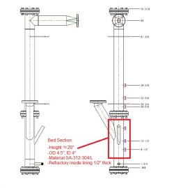
Hi, I’ve been reading about induction heaters for a while and this is by far the most helpful page I have come across yet. I’m looking into induction heating as a solution for a problem I have with my PhD project. I need to heat a 4" hollow SS cylinder 20" with refractory material inside. My calculations show that I need 2KW of heat. I’m assuming I need a bigger setup than the one you have here. In your expert opinion, is it easy to build a heater for my setup? I have attached a PDF of the setup so you can have an idea of the size of the setup (I only need to heat the part highlighted in red)
Ahh can’t make it to work. I used 330ohm resistors instead of 240, plus the 7812 to feed the gates.
Used a 7uH~ coil with center tap (7uH total). 310nF divided into 5 capacitors, what would give around 108KHz. But all it does it blow the fets.
I read that a big ferrite inductor would not be a problem, so I started with 8mH, but since I already blow 2 fets, I won’t test again before I realize what is going on.
I used a MOT winded to give me 16,8V on a 25amp bridge and a 6800uF capacitor.
I tried this method but found it would sometimes fail to resonate properly so went with this method instead. It may well work ok with a bit more tweaking.
I have been a home constructor for many years but am fairly new to power mosfet ccts. I have seen other designs based around the mazilli ZVS driver using 2 chokes to feed the drains either side of the work coil thus precluding the need for a centre-tap. Do you forsee any pro’s/con’s for this arrangement.
karan, for non-ferrous metals you will need to to higher frequencies and power levels. This little curcuit will struggle with that.
heaterhotter, No dont use these capacitors, they are not meant for use in this way.
Hi
This seems like a great simple project and I am just getting together the parts now.
1 question about capacitor type, would a microwave capacitor be safe to use in this circuit? They are rated for high frequency and 1000 to 2000v .8uf to .98uf
One example I have is measuring 0.977uf with an esr of 0.7257 ohms, is that considered a low enough esr for this circuit?
My biggest fear is overheating this metal can capacitor that is filled with oil and blowing it up, burns, a mess, bad memories, things to avoid 🙂
Hi rmcybernetics
Thank for your explain in DIY induction heater. I am follow your advices ,everything is perfect.
I would like to know , If I would like to heat with non-ferrous like aluminum,silver,…Do you have any products that suitable for this case or Any products can heat more than curies temperature ?
Thank in advance.
I built the circuit and it works well, but instead of the 240Ohms i used 20Ohms, what reduced the mosfets temp. I use these Mosfets
http://www.vishay.com/docs/91482/sihg73n60e.pdf (600V, 70A). The Choke used is a inductor from coilcraft with 22uH and ~2mOhms resistance. The problem i have is that the device does not heat above slight red, and i want at least to reach curie temperature. I tried to use a 10uF pulse capacitor but the coil gets hotter than the workpiece (10AWG!!!!!!!!). Another problem ist that i cant measure the frequency, beacause the multimeter dies, if connected to the coil, and on the gate it measures (probably wrong) 4MHz. (Heater coil: 5+5 10AWG, capacitor: 5*0.1u MKP or 10uF Pulse Capacitor). Does someone have useful tips?
I answered my own question by reading the "pushing it further portion on the cap configuration. Multiplying caps in parallel increases total capacitance. Cheers.
Thanks a lot RM Cybernetics,
When you say "add more parallel capacitance", do you mean larger value capacitors? or more of them?
I get the "current sharing" effect….
it is my understanding the resonant frequency is determined by the relationship of the capacitance rating and the work coil inductance….
….so, larger value caps and then work out the current sharing by adding more of them to reduce capacitor heating where needed?
YOU’RE AWESOME!!!!
Brian, Diodes might be failing because of voltage spikes or because of losses at high frequency (Frequency is higer with fewer turns). Try adding more parlle cpacitance to bring down the frequency to allow for more current.
Rob, Use a bigger choke to limit the current or more turns on the work coil.
Ok, Thanks RM Cybernetics!
I have successfully built a heater with:
12v 30A led psu hooked to 12+/12-
Choke is 14 turns #16 magnet wire on 20mm powder core
4+4 of #14 magnet wire
Caps are .68uF (using between 3-7 at a time in an attempt to increase current flow with seemingly no effect on heating)
Irfp260n mosfets
1kv 4007 diodes as suggested
240 Ohm 1/2 watt resistors
I did use an open loop copper attenuater as noted prior (I cut it along its length so it’s not a closed turn)
I have gotten it to heat up pretty hot but would like to push it a bit more.
I attempted to take turns off the coil down to 2+2 (burned diodes?) and back up to 3+3 (diodes safe) but no more resulting heat than I had before.
I then reduced my choke turns to as low as 8 before it fried my switches and back up to 12 turns to avoid failure.
I have not been able to reach curie yet.
Question: Is there a balance to be struck between turns on the choke and turns in the work coil in order to increase current? It seems my PSU is sufficient…..something is telling me I need to, somehow, "open the flood gates".
Thanks (a lot) in advance,
Brian
I am interested in building this circuit with a lower operation power. I would like to heat a ferromagnetic rod, lets call it a nail, to around 200 C and stabilize it at that temperature using a feedback loop. Is it possible to use mosfets with lower current ratings and a smaller capacitor bank in order to reach this lower temperature? Heating it to red hot is cool but not necessary.
So, I’ve built a functioning unit in my cylindrical design. It variably heats up different sized loads but not quickly, and not to curie temp.
The high points:
12v 30A power supply fed from 12v+(line)/12v-(ground)
Work coil is #16 magnet wire, turns=4+4, wrapped on a glass bobbin and inside a copper attenuater with an open circumference.
Choke- 8a, 100uF prefab (about 3/4")
Caps- 3 each 1000v .68uF polypropylene
Diodes are 4007’s 1000v
Resistors are 240ohm 1/2w carbon film
Mosfets are irfp260
I attempted to change the coil to 3 turns of #14 bare wire (no shorted turns) and removed the attenuater and a diode popped. I rebuilt the prior coil, replaced the diodes and it functioned again.
Do you think the un-attenuated EMF destroyed the diode?
Thoughts on beefing it up to get to curie temp?
THANKS!
Nice work Roberto. Ian, You will probably need more than a 10x probe to be sure of keeping your scope safe from voltage spikes. Put the eath clip to the batter negative terminal and then you can measure the waveform on either side of the coil. What you will see is one hald of the resonant sine wave form.
Hi RMC
I have made a couple of heaters – Both work fine & I’m slowly moving towards higher power to give quicker heating of my work pieces.
I wish to use my USB oscilloscope & PC to see the wave forms around the circuit & check frequency etc
Can you advise me where to connect the earth clip on my probe to on the circuit so I don’t fry my scope?
Should I use a x100 probe (when I’ve made one) so that I stay safe? or will standard x10 be ok – my power supply is 24V DC (battery)My first circuit oscillated at 230KHz and draws 16 amps.
Brian, The copper sleeve might act like a shorted turn if it is in close proximity to the coil. It would be better to have it split into isolated sections to reduce eddy currents.
Brandon, thanks for sharing your project. Congratulations!
Hi
I took a picture of the circtui working and I wanted to share.
Thank you for sharing this project.
I feeded it with a little bit more current and managed to get a nail red hot in aprox 90 seconds.
Some curiosities if you see my project post #5246 you will see I used aligator clips to conect the main coil to the circuit. Later I read in the article that these conections sjhould be short and with good diameter copper wire. Well mine just were too thin. Thinks go ok when I place ferrous material inside the coil, but if I place aluminum or copper the plastic in the aligator clips start to melt and the aluminum piece of the copper does not get hot. I did see on youtube an induction heater melting aluminum so I thought mine would do this as well.
Working current is now aprox 5,25 when getting the nail red hot.
Hi, I was able to get my circuit working reliably and was able to get a knife red hot in about 15 seconds. I used all of the components you used including zener diodes between the source and drain for protection. My main issue I think was my torroid core inductor that I wound myself. Not really sure what was the issue with it, but I made a new one and now it works like a charm. Thank you for the article!
Wow, I’ve been studying this project for six months. Thank you to everyone involved.
I am developing an innovation on this and wonder about the effects of the work coil on the other components.
As you can see my design is cylindrical with the circuit wrapped around the coil, outside of an insulated copper sleeve meant to act as a magnetic planewave attenuater with the purpose of redirecting the flux away from the rest of the circuit and back through the middle of the work coil.
Questions:
1. Is it practical to attempt a build with such small tolerances or will the flux interfere with the driver, prohibiting it from operating?
2. If planewave attenuation is realistic; would the sleeve itself need to be grounded, isolated, biased?
Thanks in advance,
Brian
Brandon, Roberto, Unfortunately I cannot comment on every different version and different transistor/capacitor etc. Pretty much everything that I can say about getting this project working has been said either in the article or comments already. Have a good read through and you should get really valuable information from the posts of others working on the project too.
Hi this is my second post. Picures of my induction heater have benn posted on first post.
Today I managed to make it work.
Basically I changed the power supply from a 12 v 7 ah batt to a 24 v 2A transformer (able to deliver up to 4A aprox). With this setup I managed to see my induction heater heating up a small nail. It did not get red hot but was hot enought to vaporize water. Thank you for sharing this nice project.
I did try with a smaller diameter coil but that did not make the heat more powerfull. Is there any thing besides higher current and voltage that can make it heat up more ?
Tks
Roberto
Hi I am building your induction heater project
I used
2 capac de 224k
2 mosfet IRF540N
(option to use W40N20 mosfet)
coil 8 turnes enameled copper 12 awg
Batt 12v 7ah
current consumption when powered up 2,24 to 2,44 A
A picture of it is here
https://dl.dropboxusercontent.com/u/21484405/induction%20heater.JPG
I know I am using too little power but I was expecting at least a minimal heating of a small metalic (ferrous) piece I placed inside the coil.
I do not have an oscilloscope, can you give me some suggestions to see it working ?
Perhaps a smaller coil, or perhaps change the mosfet to the W40N20 or just rise the input voltage. Also change the capp bank perhaps. Any hint would be very welcome. Tks for sharing this interesting project.
Hi, I got the induction heater working at one point, but my capacitors started smoking and now they bulge a little bit at the sides. This was after running it for about 3 minutes. I used the same capacitors that are used in the article. Anyways, so I replaced them with Mylar capacitors, would this be okay?
Also, one of my MOSETS burned up so I found these IRFPS3810 but it doesn’t seem to be working, one of MOSFETs gets really hot and starts smoking. Maybe they are too slow?
Here is a video sent to us by Doug. Here he shows an example of using a pancake coil.
Here’s a picture of the physical circuit
Hey so I’ve read this article probably a hundred times these past few weeks and I’ve been super excited to put one of these together. I’m having a bit of a problem though. One of my irf540’s will overheat and smoke almost as soon as i turn it on. The choke I used was orginally 61mH and i took about 2 winds off. I measured my coil at school to be about .2mH which I removed another turn and a half from. The caps are .1uf 1000v. At first I didnt have the lm781t or the 1n4740a but I had them and saw another schematic using it so I figured it wouldn’t hurt. I originally tried the driver circuit exactly as the article on my breadboard and i got the smoke so I added the extra components and put it on a perf board to no avail. Its probably worth noting also its only one MOFSET that gets super hot and the other does nothing. Not sure if I wired something wrong or If Im doing something toatally wrong or whats the deal but any help would be awesome. P.S its being run off a 500w psu with the 12v rail at about 10A. The first one I used went to protect the second one caused the heat problems,
1. No, but it might be useful to watch your DC input to ensure it never drops below 12V.
2. It would need to be huge. Google for PSU capacitor calculations for details.
3. Yes you can parallel more capacitors onto it which will reduce the operating frequency.
I just received your power and coil modules to try. A couple of questions. (1) No scope; can I be sure the voltage for the MOSFETs is under 100v by watching the DC voltage input to the power module? I’ll put a variac on the transformer input. (2) How much capacitance is good on my power supply DC output? (3) I have capacitors from induction cookers that should be suitable (I think) – OK to parallel some of those across the coil to double the capacitance (will that half the frequency)?
Thanks for a great-sounding and -looking product and thanks for the help. Oh, the reddish cup near the coil is from a TIG welding torch and I plan to put it inside the coil as electrical insulation against shorting out from the piece I’m heating. The transformer weighs over 4.5kg so I think it will supply good current.
What is the maximum temperature that can be obtained with this heater? Assume the material to be heated is thin copper wire, variable quantities. What can be adjusted (besides power) to tune the heater for this. How can I achieve the optimal setup for maximum temperature?
David, it’s easy to melt copper with a good inductive heater, provided you’re putting out enough magnetism. One thing to note is magnetic field strength of a coil is dependent on current and not voltage (B = (material permeability) * (current) * ([number of turns] / [coil inductance])). You could have 5 volts or 50 volts at 5A and the field strength will be the same for both voltage levels. If you really want to dump some good heat into the copper to make it melt, up your current through your primary work coil. If you’re worried about power supply wattage ratings, use a transformer to get your voltage down from 24V to 6V (or whatever your incoming is down to as low a voltage as you can safely switch). Just in this example, you’ll quadruple your current (P = V * I) which will in turn give you more to work with. In any case, it’s the current you’ll want to modulate and not your voltage. Give yourself enough voltage to make your circuit work (drive MOSFETs and such) and let your current do it’s thing.
I plan to use the induction heater for melting small amounts of copper. I hope to reach the required temperature. The copper I’m talking about is small diameter wire 0.1 to 1 mm. I plan to use a DC power supply that can be adjusted between 0 and 30 V and is current limited to 5A. I would only be melting small amounts at a time. Tens of grams to maybe 100 grams max. Do you think the induction heater will get the material to the required temperature. Copper melts at just above 1000 degrees C.
I plan to buy a built model from the shop to ensure best quality build.
I want to use this device to obtain hot water. The water pipe that will be into the coil must be from copper or steel?thanks! adrian
Just curious on your capacitor arrangement on this one. I think the reason your capacitors are getting hot is because of how they’re wired into the circuit. Normally a capacitor being used as a resonance component is wired in series or parallel with the inductor(s) they’re meant to resonate against. In this circuit, we have two main coils (the primary is split in half at the center tap and is essentially two coils placed on top of each other) and only one capacitor. In order to get each coil half to resonate, the capacitor should be hooked from the positive side of the primary work coil to ground. This puts it in true parallel with the inductor it’s resonating against and will cause actual resonance to occur.
In other induction heaters I’ve seen/built, the main work coil has been a single piece driven in AC by either an actual AC source or a high powered, complex inverter that provided the signal and was tuned to the resonance. The main inductor was bridged by the capacitor so that there was always a high and low voltage reference point. When the waveform flipped, so would the voltage levels across the capacitor and inductor. In this design, the capacitor is essentially connected to a ground and an open terminal. When the waveform switches, the capacitor switches it’s ground pin and open pin. I’m somewhat surprised this circuit resonates at all, let alone does what it does without burning up in the process.
I built the circuit here with the only modification being that I used two capacitors instead of one. Each capacitor went from the center tap of the primary work coil to its respective mosfet drain (so connected one side of each between L2 and L1 and then ran each to a mosfet drain). I powered up the circuit and ran it for several minutes (5-10) with no adverse effects. I was even using mylar capacitors and ran my mosfets using 1k resistors. I couldn’t make it not resonate. I even used the first diodes I came across (ended up being Zener) and it still resonated.
So all the people having trouble with this, I would suggest trying to put your caps in parallel with each half of the work coil. Like I said, I had "junky" parts (stuff that has been deemed here as not fast/powerful/responsive enough to run) and I couldn’t make it not run. Provided you have the power supply (can’t make miracles with that), this thing will hum right along, adjusting itself like it’s said to and working just fine.
Connecting the Litz Wire like this is fine.
Is it possible to connect a 20 amp Litz wire to the induction heater by soldering a single wire from the inductor to the middle of the winding of the litz wire like on a non litz wire(copper cable)?
or would that short the wire out thanks.
Higher input voltage and therefore more current.
Good morning, I have a doubt, if I wanted to increase the magnetic field (up to 90 Gauss at least) keeping the resonance frequency = 100kHz, which should change? Features that can be used: coil wire diameter 4 mm, total length 1m, 6 capacitors of 0.33 uF each, resonance frequency (shown on the oscilloscope) fo = 100 kHz, with this the indutancia of indutor 1.27uH , tension between the capacitors = voltage in the coil(indutor) = V_entrada = 41 V (peak to peak 82 on the oscilloscope), doing some calculations:
Z_equiv = sqrt ((Rl ^ 2 + (Wo * L) ^ 2) / ((1-C * L * Wo ^ 2) ^ 2 + (C * Rl * Wo) ^ 2));
I_entrada = V_entrada / Z_equiv;
I_entrada Iindutor = / (C * Wo * Rl) Rl: resistance inductor
obtaining the current in the inductor (coil) of 49A and using this in the simulation program Opera 3-D get a maximum magnetic field of 40 gauss
(Adjunt photo )
Jed, No. High current is needed to make a strong magnetic field in order to induce current in the metal workpiece. Higher frequency will heat smaller items and heat the surface more quickly due to skin effect. At higher frequencies the transistors will be less efficient however due to parasitic losses.
by the way, kindly explain to me the resonant frequency? would it be good if its lower or higher? Because I have a two toroid inductor with differents sizes and planning to connect it on series to increase the inductance to lower the resonant frequency. What would be the effect of lower resonant frequency in the circuit and vice versa?
hey, can I use a low current power supply? like a 250mA transformer combined with a bridge rectifier. Why do we need high current?
Bud, Energy savings from induction cooker tops are becasue only the pan is heated and less heat is wasted by heating the air around it.
ridwan, You need to put a choke in it. Other than that I can only assume you have not built as described, or some of your parts are faulty.
Man, thanks for that super useful and simple design!
I built the circuit as you recommended and I got it oscillating. but the problem is using 15v power supply, I am getting a sine wave with just around 2v peak-to-peak. And the second problem is teh circuit is not drawing any current. some 20mA is flowing through the gate resistors, but none through the coil. by the way I built the circuit with out chocke and it is actually oscillating at very low amplitude as I just pointed out above.
I would love to have as much heating capacity as yours. my supply is 30V,10A.
new person here, stumbled into this area looking for info about induction heating. interesting stuff. i will try to keep it short but need to share a little so whomever replies will understand what started this for me, I knew a little about induction heating, saw and ad on tv for the little counter top induction cook top (nuWave) bought one, they claim 70% less power to cook something over resistance type stoves. SOooo my idea was , why not use a cleverly designed induction heating element to replace the resistance type element in a water heater? here is were my web search began , now I’m here, any comments or ideas , water heating is a big part of a households consumption , 70% less (or even 30-40%) would seem like a good idea. I then heard that the "on-demand" water heaters were induction heated, is this true? comments , info, ideas…..?
like this? ok I’ll try to ask my mates to make up their mind. Happy New Year.
No. Load -ve should go to GND on the heater circuit. Distance is not a problem as we can deliver our products worldwide.
you mean like this connection in the picture?
do you think I can still control its temperature using that circuit?
Please give me a picture of where I can connect it in order to combined this two. Please. It will be very helpful for me to understand this. I usually want to buy your devices but your place is too far away. 🙁
Not really the best way to do it, but you can just connect up the induction heater power terminals as if it is the load on the other circuit. You will need to keep the PWM frequency very low though otherwise the resonator may not get chance to start up between pulses.
Can you please tell me where I can connect the Pulse Generator output (Two RED dots) to the induction heater circuit as shown in the picture?
If the two combined, do i need to supply 15V DC to the induction heater circuit or the Power pulse generator will supply it. Thanks for answering.
Do you think this will work if I follow all the ratings of your given circuits?
Michel, As mentioned in the article, you can not use most IGBTs due to them having a large voltage drop.
Hazem, you really need the capacitor which unfortunately limits the frequency. The resonating coil/capacitor allows for a much stronger current flow in the coil. You would perhaps need to make a set of different resonators to try out each frequency.
Hello, I am pretty much a noobie regarding the topic but I need to setup up an induction heater coil to heat up an oil sample for my thesis. What I have done so for is connect a variable frequency EM generator to an amplifier and finally to a copper coil. What I was hoping to do is to see how the heating changes as I change the frequency, however I barely got any heating until I put a capacitor in parallel which eventually burned. Is there a way to make a setup where I can still use the generator to vary the frequency as I want or would the frequency still solely depend on the capacitance and inductance of the coil?
Hi I need to do the same proyect but using IGBTs Do I just need to change the MOSFETs for IGBTs using the same configuration????
Thanks
Jeff, You need to connect DIS to GND to activate the circuit.
Lasse, You should always add a capacitor between the output of a voltage regulator and GND as this helps keep the output stable. Value is not critical, but something around 330uF is fine.
Hi, I cannot get my circuit to oscillate after putting a regulator in there, like in a post #4649. I figured that I need a condensator after the 7812 regulator and probably before too. I was wondering how large condensator should I use?
Just purchased the induction heater driver circuit and can’t seem to get it working.
I made my own coil out of 1/8 copper pipe that measures out to 1.49 MicroH. I am using 2 .22 HF MicroF caps for a total of .44 . This calculates out to 198K Feq. For the power supply I am using an Omron s8ps-30024cd – 24V 14A Power supply and have it set at 22.2V output at this time.
The board LED and fan powers up, but no output at the coil and only milliamps draw from the supply.
What am I missing?
Use two types of choke, to know what was the best, the first of 19 turns (12 AWG), and the second of 10 turns (14 AWG). It turned out that the best was the 19 laps, 19 turns the choke warmed faster than 10 turns.
Do not know if my problem is the capacitors that are very small (.01 uF x 10) or my choke. My work coil are 8 laps, use 14 gauge wire.
The power supply is a simple 12-volt battery.
The 240 ohm resstors limit the current to a maximum of 50mA per transistor. The actual current will vary depending on operating frequency.
Hi, I was wondering how much current the mosfets draw from the 7812 regulator?
Brad, No. There are actually a lot of variables that will determine the workpeice temperaure so I can not really help with that.
Hi,I have a problem with my induction heater, and it takes a long time to heat the piece
The components are
L1 = aprox 2mH I’m not sure
L2 = I don’t know (8 turns, 12 awg wire)
Power supply, battery of 12v
mosfet 30nf10fp
diode 1n4007
resistors 220ohms
capacitors 10x.01uF 1600v
Do you have any tables or data on what equivalent temperature if you produce a value of power? I mean if you produce 300 watts, what will be the temperature of the metal inside the induction coil?
Brad, Yes you can but you will need to use our Impedance Matching Transformer Kit as it will let you drive a single coil winding and will allow for better power transfer.
Paul, While that could work, it seems it would be over engineering something that could be done more simply. You would be better off heating the water directly using a simple resistive heating element similar to that in a kettle.
Dear RMCybernetics,
This isn’t a terribly technical question as I haven’t yet tried to build this beast, however I’ll throw something out and see what you think. When I look at the heat generated by this device, and realizing that one could optimize through choice of material to be heated and position the induced heat, when I further consider that you have water flowing through copper "piping" as a cooling mechanism, well if you removed the heat sink and possibly slowed the circulation of water to let the copper piping heat up a bit, might not this make a nifty little personal heater now that winter is coming on. The "radiator" heat would also be the non-drying type that is nice in the dry winter.
So am I missing anything or is this plausible? Has anyone on your end fiddled with this? While I don’t have an engineering background or education, I do have some advanced degrees, If I have a go at this in the New Year would you consider offering guidance? Many Thanks,
Paul
can i use this kind of coil to your circuit? because i need to use this in order to heat the clothes iron like in induction cooker.
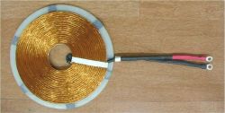
Peter, Adding zener diodes between gate and source pins can help, but it is also down to wiring. You need to keep everything very neat, and have some capacitance close to your transistors too.
Ian, No, you need to use smoothed DC. You need to se the PWM frequency low so that during each pulse there is time for the induction heater to begin oscilating and stabalize. Also modulating it produces voltage spikes which can destroy the MOSFETs if they are too frequent.
Brad, To control the temperature you need to modulate it with a PWM circuit.
Nate, Even when the coil is empty there is a lot of high frequency current flowing which will heat it up. There are losses due to the resistance of the coil and these are also exacerbated by the skin effect. If not water coled, it will soon overheat.
I don’t mean to be argumentative, just trying to understand, but regarding my build with the 1/8" copper tubing for a work coil: Why would it need to be water cooled to keep it from heating up when the coil is empty?
How is it that mine is getting so hot when the coil is empty, while others, like Doug’s (electronicsNmore) video, for example, shows it being used with the work coil sitting on a towel, and barely warm after using it to heat something? And in his video, he’s only using 12ga solid wire.
I _thought_ that the work coil would itself be heated only by the radiant heat from the object being heated inside the work coil.
Is my 3.5-turn coil (like your brass-tube design), with what I assume is a low inductance, likely resulting in too high of a frequency, causing the coil to heat itself? Would your brass coil overheat while empty if it wasn’t water cooled?
Thanks for putting up with my stupid questions and thanks for the website.
hi guys, i’m trying to invent a clothes iron made from induction for our final year engineering project. can you give me some circuit for it or some calculations to compute the amount of heat to be generated by induction heater. Please help me. And how can I control the temperature of induction heater?
Hi again RMC
I wish to power my induction circuit with a transformer & full bridge rectifier which supplies unsmoothed 30 volts DC & plenty of current capacity.
I wish to use a PWM-OCX for soft start and power control. All switched by a simple timer switch, so that on starting the timer , the heater ramps up & runs for a repeatable length of time.
1. Will the PWM-OCX operate properly with an unsmoothed 30 volt supply?
2. As my supply voltage will be 30 volts I presume I still need to control the gates with a 7812 regulator. How exactly should the system be connected? – A complete schematic diagram would be appreciated.
3. You mention setting the PWM frequency at about 50 Hz. Can you please explain the theory behind this.
Thanks for the Heater idea and great support! I have problems with FET oscillations. Can you help? I used in my setup 10 Volt regulator, SOD-57 diodes and IRFP4321PBF FETs, on the Power side I have 47uF and on the regulator 10uF. I am driving the heater with about 20AMPs. I also tried IRF540 – looks like there is less of spiking in this case but FET is under powered. Due to the oscillations FETs are getting hot. Can you help?
Thanks,
Peter
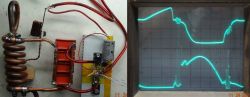
Nate, the coil needs to be water cooled.
Ian, It is possible that the 12V rails are not evenly supplying current and therefore one is being overloaded. ATX PSUs are also often rated for peak power so perhaps it just can not deal with that power continuously. HF feedback is also a possibility. You can connect chokes in series and adding some capacitors paralell to the 12V output can help filter noise.
Hi RMC I’m still working on uprating the performance of my induction heating circuit which works reasonably well from a 12 volt PSU (700 Watt ATX with all +12V outputs ganged together – rated at 38A which equals 456 Watts). The current as I stated in my earlier post starts at 5 Amps with nothing in the work coil which then rises to about 12 Amps with a steel bar partly inserted into the work coil – In my world 12 Volts at 12 Amps DC equals 144 Watts. If I put the steel further into the coil the Amps go up to about 15A (180 Watts) and the power supply shuts down. This is shutting down at less than half the current spec of my PSU. Can you help me to understand this phenomenon – what is likely to be killing my PSU which is new & just needs restarting each time to bring it back into operation. Could it be some kind of funny HF feedback? – If so how can I stop it happening. I made two induction chokes & the circuit worked fine with either of them. I then tried adding the second one in series but it didn’t appear to change anything. Do chokes work like resistors when connected in series?(R=R1 +R2) Or do I need to increase the coils on just one core to increase the inductance? I’m considering buying one of your 24volt 15A (360 Watts) power supplies to give my system more capacity but am worried that I’ll get the same safety shutdown of the PSU as I increase the work load. My circuit is built very much as you specify with all your components except for the choke which is eleven coils of 2.7mm diameter solid copper transformer wire wound onto a ferrite core 50mm O/D and one centimeter square section.
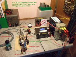
Here is a photo of my setup.
Newbie question: Is the work coil supposed to get hot when empty?
Like whisk, my coil got very hot and melted the solder connecting the C1 caps very quickly with the work coil empty.
The coil is same design/turns as your "Pushing it Further" design, but made of 1/8" copper tubing with a 7/8" coil ID. Is this too small for a 24V 15A power supply?
I increased L2 from 1mH to 2mH and that of course helped. It can be run for about 25 seconds before the empty work coil heats enough to start melting the C1 solder.
Any suggestions? Will I need to add the PWM to use the current power supply and work coil?
Thanks.
Just use one winding and leave the other unconnected.
I have an inductor just like the one you have for sale. It is a four pin and just like that green one for sale, there seems to be two separate coils on the same toroid with four possible wires sticking out. For the choke then, how do you hook it up? Just use one side? Series them? Or Parallel? Thanks.
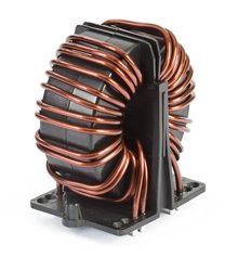
Seems likely that one or more components have been damaged.
Greetings. I’m trying to use on this circuit :
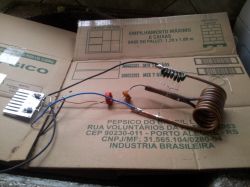
2 40NF10, 2 N58822 diodes, and some chinese capacitors. The thing is that in the first time I did the circuit, it worked, not as good as yours but still that was something. Now, everytime I turn it on, one of the transistors get pretty hot, and sometimes it burns. And the capacitors don’t seem to get any alteration in their temperature.
I tried to read some comments, but I’m lost in this case. I wish you the best for this awesome project, and I hope you can help me to make mine work aswell.
Btw, the circuit is open now, because I was puting a new mosfet
Thanks
Thanks Doug for sharing your induction heater video.
Yes, but consider the the ipmedance of a reactive circuit also changes with frequency. If you add more capacitance, it will lower the resonant frequency and will likely draw more current for the same input voltage.
You can also use an impedance matching tranformer so that you can have more flexibility for your coil design while drawing as much current as you can. For example you put just a couple of turns at the primary side parallel with your capacitors, then if you want your induction coil to have more turns, you wind the transformer secondary with a lot of turns to step up the voltage.
Okay, so the work coil’s impedance limits the circuit’s power to some finite value. That makes sense.
This means that there are no other ways to increase the power besides increasing the input voltage and adjusting the choke, right?
No, the impedance of your heating coil assembly will also limit current. The choke is also necessary to prevent high frequency current reaching your PSU and damaging it.
Is the choke the only limiter of current? Lets say I hooked up a heavy duty server power supply (12V at 120A) and kept lowering the inductance of the choke. Would it be possible to use all the available current from the power supply, giving me a 1.5kW heater? Obviously I would have to use much bigger components throughout the circuit, but could this work?
That is a very nicely made graphic! There are a few suggestions I could make about wiring it up. Keep in mind that the connecting leads between the CRO-1 and the coil assembly will still form some part of the resonant circuit. The bulk of the resonating current will be directly between the capacitors and the coil, but the small amount of inductance from the connecting leads will also have some effect on the impedance and therefore how much current will flow. This effect is more significant when using low inductance coils like our center tapped induction coil assembly as even a bend in the connecting wires can change the current flow by about an amp. This coil uses a single copper tube and has the centre connection simply soldered onto the middle of the central turn. This connection method is fine as long as the coil is kept cool enough not to melt the solder.
There is also another alternative that may be more suitable for your application. You can use a centre tapped transformer connected to the CRO-1 and then have the output connected to a standard two terminal coil. Using this method you have more flexibility for your coil design and can also keep all the bulky capacitors and transformer out of the way with the CRO-1. We are currently testing out some transformer cores and designs which will become available to buy in the coming weeks.
The solenoid should not be directly affected by the induction coil, but it might have energy from the fluctuating field coupled into it as if it were the secondary coil of a transformer. The solenoid is likely to have a high number of turns and could therefore cause a high voltage to be fed back to your solenoid drive circuit. The significance of this will depend on how much the resonating field couples with the solenoid.
I’m presently developing an adaptation of a RepRap 3D printer in which I’m intending to heat the hot end with an PWM supplied (not shown) induction setup. The picture illustrates what I have in mind. It uses the CRO-1 but has 4×0.47 1000VDC rated caps (EPCOS 32653 metal-polypropylene). My calculations suggest about 205 KHz resonance based on the copper tubing and 2.8 turns. Owing to space constraints I decided to split the large caps and induction coil from the oscillator circuit. Also I encased all but the coil in metal enclosures. Some of the wire gauges illustrated are possibly too thin but apart from that, any comments about the interconnect between the oscillator and induction heater? Also, I have a solenoid about 5cm above the coil and a concern is whether there would be meaningful interference from the induction circuit to cause the solenoid to malfunction. Lastly, I thought about drilling the coil and brazing a stud to it which would be the soldering point for the L2 tap, avoiding the bypass surgery with the small plastic tube. Comments on any of these features and how I could improve upon the design?
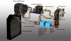
The reactance of the transformer increases with frequency and therefore less power can flow. The only solution is to increase the input voltage.
I forget to mention : instead of 10K resistors figured in schematic ,I used 4k7 ,and irfp240 tranzistors…anyway I don,t think this is so important…
Hi;I am using this type of oscilator known as mazili ZVS (is allmost the same like you presented)
I used 100 uH inductance, and thick wire in primary.Voltage :12 V ,my dc power suply can give 16 amps
The oscilator was used for powering up an flyback transformer from an old black and white TV.
I observed , at low frequencies ,below 20 khz the flame in HV secondary coil is much stronger than at higher frequencies;For example, at 250 khz the secondary output is poor ;I have almost no flame…
So the higher the frequency the the lowest the output of secondary…Why this happens? Please advice me how can I fix that?
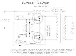
Thanks for pointing that out. It should be L83 x W46 x H60 mm. Listing and datasheet updated.
I sit in eager anticipation of the CRO-1. But in looking over its specs, something doesn’t add up. It looks like we have a couple of TO-220 heat sinks under the 40mm fan. However, the dimensions of the product are cited as 45mm x 50mm x 20mm. Now the heat sink is roughly 35mm wide by 35mm tall (not counting the pins underneath). The fan is seemingly a 40mm unit. Yet it’s occupying only half the longest dimension. Assuming it to be half, and allowing a little extra space around it, we’d have a product coming in at roughly 90mm x 45mm x 35mm. Not 50mm x 45mm x 20mm. What gives?
Nice work Robert. Thanks for sharing your photo.
caleb, No. The choke also serves to block high frequency currents from getting back to the power supply rails. We have 1mH 16A inductors which are not expensive.
Fady, Supercapacitors are not suitable for this circuit. Make sure you have fast diodes. No you cannot just wire it to a transformer. This induction heater must be driven at resonance to work..
sharad, You need a whole different setup for higher power levels which is beyond the scope of this project.
Thanks for providing this good information about induction heating.
I want to build induction heating setup,i want to 230V AC supply as a input supply.Reference to current circuit which components will be required to change?
I have another question ,can i simply put a steped down transformer into the socket and put on the other side of the trans the resonant tank and then would i have an induction heater (with resistors and fuses for protection)
Hello i have another question,i made an entirely different circuit this (same diagram different parts) and yet nothing happened could you tell me that if i replace my capacitor with a super capacitor will it work? because the previous circuit had it and it worked ( a little)
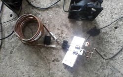
Could you simply use a current limiter instead of L2? It seems that a silicon current limiting device could provide variable power to the load.
2mH inductors @ 10A can get expensive, but a 10A MOSFET current limiter should be pretty cheap, and adjustable.
Any thoughts?
Thank you.. with just a few of changes it worked great, first I went with the irfp150n transistor, then used 12 raps of 16 awg mag wire on the choke,10 1uf caps and the source is to neg instead of ground. Next I’m going to try 2 24v/15a power supplies hooked in parallel, this should get me o 720 watt…
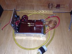
Oh,thanks a lot i understand more now
A larger coil will have more inductance, but heating effect and feild strength are not directly proportional to inductance in this induction heater. Your smaller coil would offer improved coupling due to there being less air space between the windings and your sample being heated. A low number of turns are used as this keeps the impedance of the circuit very low, thus allowing more current to flow.
Thank you for answering,i have another question,i am puzzeled,i learned that a coil with greater diameter has better inductance but when i make a smaller coil i have better heating,why is that and if more turns make for a better magnetic field why only use 4?(regardless of the need for a high resonance frequency)
Well going from a 24V PSU to a 12V one is going to cut the power in half. Also, as mentioned before, ceramic capacitors are not suitable.
RMCybernetics,i made my own induction heater from your circuit diagram and it worked but the metal screw only heated up a little bit because i had a very small power supply (24v,4A),then when i changed the power suplly it worked a little better but still not much heat,then after i went for a 15A,,12V power supply,NOTHING HAPPENED!,nothing heated up,niether the coil,or the choke or the transistors,there was a voltage through the input and output,but nothing anywhere else!,i replased the capacitor with another one but still nothing happened! do you think you can tell me what happened ?!and if it is needed,i’m using a ceramic capacitor (x1y2),2inductors in series as a larger chocke,and the transistors can wdthstand 20A and 400V douu need a picture?
ejav, L1 is the induction heater coil
Ian, more input voltge will certainly improve heating. A big choke will help, but if oscillation does not start, the MOSFETs will soon be destroyed. Frequency will effect the depth of heating, but I am not sure what adjustment would be best for your application. Making sure the coil diameter is as small as practically possible will help.
NEW: Power Resonator – The DIY Induction Heater Circuit available to buy
Hi RMC
My heater is working well now I have a better PSU driving it. 12V DC input draws 5 Amps with nothing in the coil. & current rises when metal is inserted – All good.
Mine heats steel up quite quickly & as expected brass more slowly.
My coil will need water cooling again as you advised.
As I want to anneal brass locally (just one end of a tube),I need a quick heat input to avoid heating too far down the tube.
Questions:-
1. To increase the heating rate for brass would a higher voltage power supply be better?
2. Does oscillation frequency affect heating rate significantly? (I could change the number of capacitors to change that, I am currently using the six you supplied).
3. If I opt for 24V supply (2 x 12V car batteries) would it be possible to use a large choke to inhibit the initial current surge you speak of? Rather than go to the expense of using a PWM?
Hi freinds, Specially thanks for the good conversation.
I am beginer in this field and have a simple question. Does L1 or L2 in the figure represent the brass coil?
I should prepare a induction machine for catheter tip forming. How can I select some parameters of the coil such as the wire diameter and coil diameter?
Pradeep, I can not offer support for other circuits or devices. You will have to test this out for yourself.
Eli, It will not work well with an external oscillator. It is essential that the system is driven at resonance otherwise the system will be very lossy. The resonant frequency will change when adding different sized items to be heated. Yes moving closer increases coupling and will heat more. The optimum frequency used will be highly dependant on your setup. The choice of transistors, the coil parameters and the size and shape of your heated item are all significant, so I can not offer any further information on that.
@RMCybernetics –
How do you think this circuit would fare from driving the FETs with an amplified VCXO oscillator? That would remove the necessity of needing an array of capacitors large enough to cope with current.
If it at all matters, I’m in research working on a low-cost CMOS fab scheme, and I need to heat a wafer chamber to about 1000 deg C.
Is this plausible should the power handling (# of FETs, supply amperage) be increased?
Also, I’m well-versed in RF mechs, but I’ll run a few things by you anyway – first, would decreasing the distance from interior coil diameter to sample (in my case, the iron "bomb" with the wafer inside) improve heating? I’d tend to think so, knowing that the core improves saturation over a typical air-core scheme, but I’ve never built a heating device of this kind, so I figure I’ll run it by you.
Second, at what region of the frequency plot do you expect there to be diminishing returns? Obviously, if I were to resonate the FET gates at 60Hz, I’d have slow to minimal transfer. Increasing frequency yields results up to a point. My point better stated, within the 10kHz to 1-3MHz spectrum, is there that much difference between high- and low-end frequency oscillation?
Thanks in advance.
Hi, I design a thesis topic: the design of a transformer for induction heating of bearings. Can anyone help me how to make the scheme and what elements will contain. Any help would be helpful to me thank you.
can use induction cooker which run 220v Ac for induction heater application connecting coper pipe to the out put?
Is there and circuit modification required?
The Lightning Stalker, Sometimes adjusting the value of the gate resistors can help. Also a zener diode between gate and GND could be worth a try.
Keiko, the 1n4007 can work, but they are quite slow diode so will only work if your induction heater has a low resonant frequency. Ideally something faster would be needed. Anything described as a fast diode with sufficient voltage ratings would be OK.
Pradeep Kumar, This requires electricity and can not be made to work without it.
Ian, the PWM-OCm does not support the soft start modification. That tutorial is for a discontinued model (PWM-OCB). You can use an unmodified OCm, and simply use the controls to gradually turn up the power. Alternately you can use our new PWM-OCX to power your circuit as it has a built in current limiting feature. This would limit the startup current automatically (once you have adjusted the current limit control to your desired level).
Andreas, You probably would not be able to get sufficient power through this circuit to melt steel. Maybe with a very small coil and small metal sample.
Is it possible to heat the steel above the Curie temperature with this circuit?
Up to about 1000 deg C or even melt steel?
Hi again RMC
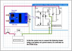
I’ve built my Induction circuit with your mosfets, capacitors, diodes, resistors & a 7812 regulator feeding the control side as per your drawings, but it won’t heat up – My PSU can’t keep up the voltage -It drops to 5 volts from 15 whilst drawing about 10 amps – Does this mean my circuit isn’t oscillating?
I attach my idea of how the intertconnection of a PWM with soft start will need to be wired to the Induction heater. Is this correct?
As my PSU isn’t up to it, I wish to have a car battery powered system (12 Volts) that has the PWM controls set to ensure that I get exact repetition of heating rate each time the system is started using a timer switch on the PWM as the cycle start). My timer will close SW1 for the preset time.
My application is annealing cartridge brass & precise, repeatable & adjustable time & heat input is important to me.
How can I convert this to induction cooker? I am planing to make dc induction cooker for home where there is no electricity available.
Can anyone help with circuit details with necessary modifications?
Thanks Robert! I had narrowed it down to the current having blown out the diodes and maybe the transistors, though I’m not positive of the latter. Could you give me the sort of specs I’m looking for in the new diodes? I have a fairly good store nearby that I can probably find something suitable.
I’m bit at home and can’t takea picture of our setup.
Keiko: Those diodes aren’t going to cut the mustard. I was using ultrafast diodes and they still weren’t enough. The ones you’re using are much worse. In fact, they’re so slow that Fairchild doesn’t even publish a Trr on them. At 24V, I’m afraid you’re going to have to buy some mail order, unless you have a very good local supply house. Do you have a link to a better picture? It’s hard to tell what’s going on there.
Cheers,
Robert
Thank you for the great guide. My friend and I are making this as a senior physics fair project, and as such we’re fairly limited in our resources. Since we don’t have an oscilloscope, we’re at a bit of a loss as to how to troubleshoot the circuit. I suspect the resonance is not occurring, but I have no way to be positive. We’re powering this with 24 volts from 2 car batteries through a motor controller, as it was the only way we could have sufficient amperage. Any advice or suggestions you may have would be greatly appreciated.
Parts: NTE2396 MOSFET (comparable to IRF540(N)), 1.98uF capacitance, 330ohm resistors, 1N4007 diodes, and we believe the L2 choke has an inductance of around .246uH.
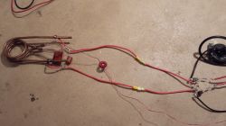
Hello. Thanks for the great site and info. I’ve been having quite a bit of trouble getting mine to work. As of right now, the transistors are getting hot and I’m getting some funky waveforms. I’m suspecting the diodes. They are some FF1001. The top trace is the gate and bottom trace the drain.
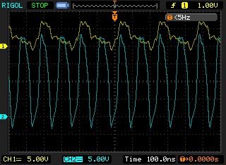
I can not answer yes or no for all the possible alternative parts that could be used. If you do not want to use the parts listed, then it is up to you. There is a lot of info above that should let you know what you need, or of course you can just try it and let us know how it goes.
sir,
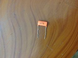
can i use orange drop capacitors(330nF){in the picture} in place of 330nF polypropylene capacitors that u have used.also can i use IRF540 MOSFET instead of STP30NF10 .will it work.
The solid wire might be easier for forming a coil, but apart from that, either will be OK. This diagram shows the addition of 2 diodes to the circuit so that it can be linked to one of our PWM Control circuits for adjusting the power of the induction heater.
The duty control of the pwm circuit is inverted compared to the output power of the heater. which means setting the duty to 100% will turn off the heating. So before turning on the power, set the duty control to 100%. You can then gradually adjust it so that the heating and flow of current is at the level you want. Any of our PWM circuits will work for this as connecting this way does not pass the main power flow through the PWM. You should also set to quite a low frequency such as 50Hz as this seems to allow the induction heater to resonate properly between pulses.
Thanks for the quick reply RMC. I’ll be ordering some components today!
I’ll get a big ferrite to play with then! – Easier to wind the cable!
I have plenty of stranded heavy gauge wire – can I use that for the inductor wire or would 2mm single strand magnet wire be better? My idea is to use the one piece of cable straight through from the power supply, through the choke & onto the load coil L1 centre tap.
Regarding power supplies. If I want to use a car battery (fused of course) am I right in thinking that you recommend using a Power Pulse Modulator. How exactly should that be connected? – will it simply go in series with the cable from the battery to the Induction heater circuit and take all the power for it? – can you give a connection schematic for this scenario?
Regards Ian
bob800, they basically wont have enough metal inside them or at the connections to support large flows of current. The ones used in this project are only able to withstand short runs at 300W. The 1000V rating is not going to help since in this project the voltage only increased to around 100V.
Ian, Too big is OK, too small could just mean not enough inductance. The one used here is 550mm od and 18mm thick. I spread the turns but it wont make a significant amount of difference.
Hi RMC I see no where in the description or Q&A postings any physical sizes for the ferrite toroid to use for the choke. Is the size of the ferrite critical, can it be too big? If I use on that is too small, I realize I could have difficulty getting enough coils of heavy wire into it. I was thinking of getting something between 3 & 5cm o/dia with a cross sectional area of about 1 sq cm. Would that be ok?
Also when winding the inductor coils onto the ferrite is it best to space them evenly round the circumference or can they be bunched together?
Thanks for the reply! Could you please explain what about the capacitors is unsuitable? They are both MKP capacitors rated at 1000V.
bob, Neither will be suitable. You can not cheap out on parts if you want to make it work at 600W.
Michael, No. The arc welder output is very low voltage. You can not just replace the MOSFETs with IGBTs. As mentioned in the article, the voltage drop would be too large and would not allow the opposite transistor to switch off
This circuit is just a simple DIY induction heater project. It would require something more complex and using more expensive parts to work at significantly higher power levels.
Christopher, Absolutely the PSU is not good enough. This is the number one point in the troubleshooting section. Please read the whole article and comments. The answers are there.
Hi RCM,
I put together the circuit using the components you have suggested; however, the power source I’m currently working with is a 25V 1A power source. The problem is that there is no voltage across the mosfet and there is very little current <<1A being drawn into the system. This is occurring with 15V going into the current. Is this possible due to the inability of my power source to drive the circuit, or some other issue you might have in mind? Thank you for any advice you might have!
Is it possible to use a 200amp ac arc welder for the power supply? by up sizing ea component ?
For example I have a couple of high current igbts
1000v / 200amp to replace the mosfets?
Hi, I’ve been trying to find an affordable 0.1uf capacitor to use in a chain of 40, for a total capacitance of 4uf. I found two such models: The first is significantly cheaper, but it is described as “General Purpose” vs the more expensive “AC Pulse, Suppression” model. Also, the second model is “Double Metallized”. Are these features necessary for a ~600W heater, or can I go with the cheaper model? Thanks!
No, it may contain some useful transistors, but you would be better off just buying the few parts that this project requires.
I have an old yaskawa V1000 drive for induction and pm motors would i be able to use this as an induction heater or salvage parts from it
A 9V (PP3) battery does not have enough power to heat a cup significantly. There is no point using induction heating for this anyway. Just a standard resistance heating element would be best.
Hi rmc,
It is posible if I try to made a simple heater to warming n boiling water in a coffee cup? I have no idea about electronic. But I want to make an induction heater for my coffee cup. I wish it can be 9volt battery, size about 70-80cm in diameter. Can you help me please?
Curiously, the first thing I did before finishing the article was fire up LTSpice and enter a few components. Got 27kHz on my first oscillations, so a little low, but now I see you have a .asc right here, I’ll pick it up and have another go. Thanks.
Facepalm! Please read and follow the troubleshooting tips and the other suggestions throughout the comments.
hi rmc i have completed the connection of all the components based on the circuit you given above but i dont get any frequency at all,what is the problem?
Great, thanks RMC!
Pancake coil pic below:
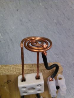
Thank you RMC!! I finally got my induction heater to work. I simple had a diode in the wrong direction.
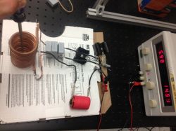
I know the diode side with the band goes on the more negative side; I’ve tried several configurations but are both your bands on the transistor side?
The center tap does not need extra cooling. The large currents circulate between the coil and capacitors. For extended high power use, you might need to cool the capacitors too. The PWM will not heat up as it is only controling the transistors and not switching any significant power directly.
Hi,
Just added a PWM to my system – works really well even with my old power supply. I assume this is because when it’s turned down it decreases the amount of power required to kick off oscillation?
I’ve also successfully built a pancake coil which works nicely although it seems to require a bit more power than a standard solenoid coil. I’ve just added the centre tapp by looping 10A wire over the coil approximately half way around the coil (Robert I think this was your plan for the solenoid coil – worked ok for me but did get hot). Picture below.
Robert regarding your question above the frequency can change the depth of heating – higher frequency heats closest to the surface and then conducts inwards, lower frequencies heat deeper into the component. Probably not an issue unless you’re heating something really large.
RMC couple of questions;
My next task is to add water cooling (I’ll make a new coil without all those pinch points). Is it also necessary to cool the centre tapp wire going to the choke? Mine seems to warm up a bit (not as much as the coil itself but still reasonably warm).
Secondly, if I run the system on low power (controlled by the PWM)and I have fan and water cooling is it likely that I’ll be able to run the system for longer than your suggested 5min? I’m only heating something the size of a medium sized coin and I’m going to try and put it in a vacuum which should significantly reduce the power required to maintain a higher temperature. It seems like it should work but I wonder if there’s anything on the PWM or even in the main circuit which will heat up regardless of how low I drop the power?
Thanks again for the great project, help and advice.
Sam
Some additional information on my setup, regarding my previous question about only 1 transistor heating up:
-I have verified that the 3 prongs of the transistors are wired correctly (source, gate, and drain), and the transistors themselves are able to handle 35 A and 100 V as you specified.
-I am using the 1N4007 diodes you specified in the improvement section, instead of the 1N5819 diodes as originally stated. I don’t know if that could be the source of the issue.
-My copper coil has 10 turns (no turns touching); it has a wound length of 5 inches and an inner diameter of 2 inches. The pipe itself has a 2mm inner diameter and a 4mm outer diameter. I hope I didn’t go too far with anything.
I am not sure there is anything else to suggest. There are a lot of tips in the article and comments. You will have to work through those 🙂
I have my circuit completely wired up with 15 V, 5 A power supply, 500uH choke, and a 10 turn copper coil, but I can’t get it to heat up anything. I’ve noticed that only one MOSFET heats up but no wires cross or touch on the other. It is wired the same way as the one that heats up but doesn’t seem to be working properly. Any suggestions?
Yes you can, allthough you may find the solder melts if not kept cool. More capacitors is better as it helps share the current and reduce frequency.
1) For the center tap, could I not just make a solenoid and solder the choke to the center of the solenoid? Wouldn’t that perform the same function as what you did since in yours both parts of the copper/brass coil are all connected and touching anyway?
2) I notice in some cases you have 2-330 nF capacitors and in some you have 6. I understand it allows the system to run at a lower frequency, but would you recommend 6 over 2? What effects will it have on the end result?
Thanks for your help!
1) Because the current is delivered to the center of the coil, then each transistor switches alternately so that current flows in both directions.
2) Probably, but it will not be simple. The material, size, shape, and position in the coil will all effect the heating. There is also the frequency, current, and coil dimentions to consider.
RMC,
I have ordered all my parts, and they have all come in. I am beginning to assemble them, and I have a couple questions. (1) Why is it necessary to have the center tap? Why couldn’t you just solder the choke straight onto one continuous solenoid coil? I only ask this because I’m having difficulty soldering the copper pipe to each other at the tap. Suggestions? (2) Is there a formula that relates the magnetic field strength or flux density to amount of heat applied (or something of that sort)? Thanks!!
We do not currently sell an assembled unit. We will have some new products available soon for making induction heaters. Check our Facebook page or newsletter for updates.
hi i want to build my first induction heater by rely on your post your schemetic your part list any way i can buy one of your induction heater like your post with 100 % assembly and test work already and i need one as example so i can look at it and do the second one how much one already assemble test good cost plus shipping i want to pay for it than make it as sample to assembly my own the second one … tell me will you sell me one you part very cheap.tell me the price i have to pay for .. thank you
Sara, a full bridge would be a different system altogether. I can not offer any help for that as it too far outside the scope of the article.
Trevorb, give us more details. Size of capacitor on the work coils, the P/N of the transistors you are using, etc. From your readings, something is not connected properly. With your work coil disconnected, you should not see the readings you are reporting. Double check your set up. Also, the MOSFETS both seem to be in conduction. The gate voltage is below the threshold range of a typical device, so I am thinking that you may have depletion mode MOSFETs instead of standard (or enhancement mode) MOSFETs? The readings indicate that both are fully on.
Trevorb, are you still out there? If so, from your pictures, your work coil is wound incorrectly! You must keep turning in the same direction all the time or else the magnetic fields will cancel out nullifying the inductance, hence, not oscillation. If you start winding a flat coil clockwise, once you get to the center, you must start the second coil out clockwise and move to the outside. I looks like you made two coils at the same time winding the same direction, flipped one over (making it now wound COUNTERCLOCKWISE) connecting the centers together. A good way of checking if you did it right is to start tracing out your coil with your finger to the center and then back out. If you change direction, that is change from CW to CCW , you made a mistake and need to fix your coil. Also, try to get it to oscillate without the load first. If you could post your control circuit up so we can take a look at it as well, with the part number of your components,there might be an error there too. Good Luck!
Kev
Hi RMC I am about to start building the induction heater I have started with creating my own PWM command Circuit I used optoelectronics 6n139 for the connection between the PIC and the MOSFET
I wonder if it works with your power circuit
and what do you think about using a full bridge???
please help me I need it for my study project
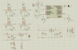
Robert, The specifics of the choke and work coil do not need to be exact. We soldered the wire directly to the side of the pipes, but leaving enough space from the end so that water cooling pipe can pe pushed over.
Sam, You will need to use a PWM as suggested in post #5013. If you set the pulse frequeny to something much lower (50Hz is fine) than the resonant frequency, then it will not cause any oscilation problems. Your arduino can be programmed to disable the PWM when it detects the temperature i s too high, then re set it agoun when it has cooled a little.
I am about to start building the induction heater into an (almost) instantaneous smoke generator, my question is how to modulate the power in the work coils so as to control the temperature of the work piece (10mm OD steel tube with 1mm bore). If is use PWM will the pulses interfere with the oscillation in the circuit? Is there a better way to allow for thermostatic temperature control? I will be using non-contact IR sensor to monitor the temperature or the work piece, interfaced through Arduino. Any advise would be extremely welcome. Thank you.
Regarding my previous comment: I found somewhere in the comment section that you used a 500 micro Henry ferrite core for the choke, is that correct? And I understand now that L1 is simply the wound work coil. If I wish to flow water through my copper pipes to cool them, how do I go about soldering or attaching the copper wire from the choke to the center tap of the copper pipes?
There is nothing about specifics mentioned about L1 in the article or comments. Regarding L2, all I see in the article is this:
"The one shown here was made by winding about 8 turns of 2mm thick magnet wire on a toroidal ferrite core."
But it doesn’t give me any specifics on the toroidal ferrite core.
The inductors are described in the article and comments. Nothing needs to change for a wider coil, but you may find that it will not heat large items so well.
I am new to Induction Heaters and currently trying to build one on my own, so I am attempting to mimic yours exactly. For your DIY induction heater design, I cannot find what type or size of inductors you used for L1 and L2 (choke) and in the pictures you provide I cannot even see L1 to get a better idea of where it plays into the system.
Secondly, I notice yours has 6 turns and the diameter of the coil is only about 2 inches or so. Would I have to change anything if I wanted to increase the diameter to 4 inches?
thank you RMC for your suggestion .
sir can i switch the transistor externally?
and all the circuit is same as your.switching frequency adjusted according to resonant frequency f=(1/2*3.14*sqrt(L*c)).and that switching frequency given to both transistor using square wave generator circuit then will that circuit works for induction heating for bolt?
A car battery has a huge current capacity. The problem with this is that the sudden rush of current when connecting the circuit could blow the transistors before the oscilation even gets started.
I would suggest using a PWM so that you can slowly turn up the power. See post #5013
Hi RMC,
I’ve now upgraded my setup to the six cap configuration and bulked up my wires and connectors (managed to start melting the insulation off my wires with a 2 cap breadboard setup). Unfortunately my power supply is current limiting and I’m unable to get power up high enough. Any thoughts on hooking up directly to a 12V car battery with a 10 – 20A fuse in line? I’ve also got access to a 24V truck battery if you think higher voltage would make a difference.
Cheers
Sam
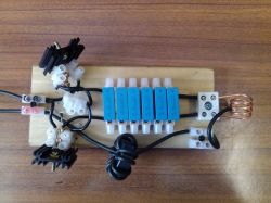
This is not the place for getting support for your cooker. Contact the manufacturer. This is only for information and support for the DIY Induction Heater project above.
Hi i have a induction cooker which whenever i power on for sure its will power trip,what could be the problem? Could it be the rectifier spoilt?
Please advise,thanks
can i use STP30NF20 …… tnx in advance
Thanks RMC, for your valuable suggestions. i will post my circuit pics soon.
Hi, thanks for the great project and fast shipping, worked great first try!
Trevorb, any luck on that pancake coil? I’m hoping to build one too but have started out with a standard coil to kick things off. Have you tried applying your circuit to a standard coil? I wonder if your problem could be coil side?
I’ve made pancake coils for an industrial induction heater which I run in a lab using a coiling pattern similar to 1) in the picture below. I wonder whether the centre tap requires coiling similar to 2) to avoid cancellation in the coil?
If anyone is interested here is an awesome summary on coil design: http://www.stanleyzinn.com/pdf/coil_design.pdf It’s for standard non-centre-tapped coils but gives a great overview of key considerations when designing a coil for a specific purpose.
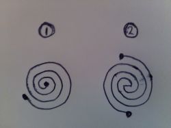
thanks for the reply. i used two irfz44n and i’ll go to 4+4..i’ll post the result after..
Frank, there is allready a gate resistor. Increasing this will slow down the switching and increase losses. To protect the gate, use a zener diode between gate and source.
Rajesh, No, just do as described.
Sachin, It could work in theory, but that is not a practical circuit. I can only offer support for the circuit in this article.
Dear sir
RMCybernetics,
I am new in the induction circuit .
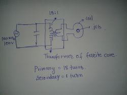
i have the following circuit diagram of induction circuit.Will it work? Because u have used a choke L2 and i am using transformer of 18:1 or 11:1 of ferrite core only.Will it work to heat a job in coil if circuit in resonant?
Thanks RMC for reply. You mean we can connect the gate pin of MOSFETs to PWM Supply instead of 15V DC supply. This way we will be able to Modulate Gate Pulses and control power by varying duty cycle of PWM Supply. I am sure the modulation frequency needs to be much smaller than operating frequency of Tank Circuit.
I have read where several people have toasted their FETs testing this circuit and curious if anyone would advise using a gate resistor for FET protection or if that would cause ill effects? I was looking at maybe a 10k in series just before the gate?
You can use pulse width modulation to control the power. I found that our PWM-OCm works very well. To use it, I connected a diode between the gate terminal of each MOSFET, and the L- connector on the Power Pulse Modulator. The cathode side of the diodes connects to L-.
You also need to power the OCm from the same power source, or create a common ground if using a seperate one. When the OCm switches on, it pulls the MOSFETs low, thus disabling the induction heater circuit.
You can now adjust the modulation frequency and duty very easily. Note that the duty control is inverted when doing this.. i.e. turning up the OCm to 100% will set your induction heater to 0%.
Thanks for reply RMC. I had one situation when i placed an MS Bolt for heating. It got red hot in one minute but current taken from DC kept increasing. Can you suggest any form of power control to this circuit. Since it is a self tuned circuit frequency variation is not possible. Is DC voltage variation the only way ?
Frank, Cons are limited power and needing a center tapped coil. You would need capacitors that are specifically designed for very high current, high frequency use.
Dimitris, You can add parallel MOSFETs if you need more current handling.
Rajesh, No, it must be the coil.
Thanks RMC for sharing your experience. I built one circuit and was able to run it at 100 KHz. I have a question. Can we split capacitor instead of coil of tank circuit???
first thanks to rmcyber for this very usufull project..and sorry for my english after… i build mine and working very well,but i have a question about a upgrade on this.. if instead of two biggest mosfet were used more than one on parallel would that work or not? thanks
I have a couple of questions.
1. Regarding the simplified self oscillating circuit, are there any cons to using this type of circuit.
2. It seems the capacitors are a big issue in terms of heat gain and I am curious what one might select for a more continuous duty system? Not sure if you must have some liquid cooling for even smaller units or if using high end low ESR caps will solve that issue?
Here’s mine. The work coil is only temporary until a some proper copper pipe arrives. It’s working quite well so far, oscillating at around 110 kHz. Thanks for the tutorial.
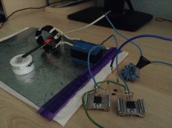
Thanks to RMCyber. for sharing this tutorial.
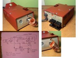
After many troubles – problems were solved.
The housing is for a shot nichrome AC wax carver. The Transformer remained, and the new components were swapped for the old. Much more versatile.
For a 25mm long x 9mm wide x 2.5mm carbon steel carving spatula to get cherry red all the way through (confirmed non-surface heating by lengthy cool down time) it takes about 9 sec. As good as needed for wax carving!
If someone sees major errors in diagram please correct!
Cheers.
[consider removing posting #5001 due to having re delved into the project]
Eureka! Finally discovered a power supply that works. I wonder which would be best for the post psu elect. capacitors to smooth adding the load; 1 680uf 200v, or 2 2200uf 50v in parralel, or 6 2.4F 4.7v super caps in series=2.5F 28.2v…?
In light of blowing up my only power supply (because my choke was too small?) I decided to see if anyone here wants to take on what I have built. I would charge basically half of what I paid for parts plus shipping.

I would go further on this kit, but in the process of the PS burning I got an extremely high voltage shock. A bit deterred to say the least.
I can almost guarante all parts are sound. Nothing had time to even heat up, as the PS fried immediately after connecting power.
Sure, I could ask question after question on here to figure the problem, but no need for my novice to be a nucence. I would rather share.
hi,can you please explain how the voltage of capasitor go up to 3*Vin ?
Added picture of setup
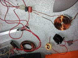
BLADE HEATER PANCAKE COIL UPDATE – Tried bigger chokes including 500uH, 1mhenry, and both in series, also wound my own with 40 turn thick magnet wire on a really large (est 4 inch od x .5 inch thick ferite torroid). I have tried all combinations of the above inductors in series before branching to the work coils. Also tried each inductor individually. I have added capacitors on the power supply and am placing the choke coil on the +15V supply to abruptly switch it on. I disassembled diodes and they tested ok and identical to unused ones. Changed out and checked mosfet by charging the gate with a multimeter in diode mode and watching the voltage change slightly when discharging gate to ground. Voltage across power supply terminals was 1.5 volt with the lower resistance chokes, but rose to about 3 volts with the 500uH choke with the thin wire (rated for only a few amps). Still no oscilation the pancake work coils (I am not reading an rms voltage from coils to ground when L2 touches +15V). Power supply rated at 15V 10 amps. FETS and smaller diameter L2 wire heating up – I think I am getting 10 amps. Not sure if MOSFETS are off. I am measuring about 1.4 volts at gates regardless of whether L2 is in contact with +15V for not with power supply on. No AC voltage measured after a split second after touching L2 to +15V, but lots of activity on the lcd display of the multimeter for a split second. I have a good spark made when touching L2 to +15V. Any other advice to try and get this to oscillate would be greatly appreciated.
Couldn’t sleep last night – so I cold forged the work coil from 3/8" (9.54mm) solid core copper wire. Should there be concern on the proximity of the choke and work coils causing interference with each other? This photo is a mock setup with the choke core beneath the rails of the work coil.
http://www.instructables.com/files/deriv/F91/ZX4X/HA4LGE2K/F91ZX4XHA4LGE2K.MEDIUM.jpg
Sound advice RMC – will be building soon. For the core I spent $1 on 3 compressed high carbon steel machine washers (5/8") which were very ferrous. Will combine these, then coat with insulation of some form. Should be a nice substitute for not having any devices to scavenge. Hope to share results in a few weeks. Kudos on the article and comment maintenance!
Just use the -12V in the same way as GND is used in the diagrams. It will work just fine. You don’t need to treat it any differently than an ordinary 24V supply. You can find torroidal cores inside old amplifiers or computer power supplys.
your right, because the difference of 24v… but will that be evenly distributed between the two +v inputs if I just use a y-splitter? Or in this case, post of the y-split, should there be two lm4812’s, regulating each input (choke and mosfets)? Also, any clever ideas on where one might scrounge up a proper toridal core? I found no blanks cores in the shop I sent for the projects other parts. As you mentioned, a bolt with many more winds would work, but im attracted to the elegant option of the torid. Form and function. Thanks!
Joseph, If it has +12V and -12V then just use the -12V as your GND connection. This gives you a 24V supply.
Trevorb, Bigger choke. I’ve used 500uH in the simulation. 2.8uH is way too small. Please read through the other comments and troubleshooting section carefully. I have mentioned this multiple times.
RMC-Trying to make a blade heater using pancake coils. I simulated with LT Spice and this calculator. http://deepfriedneon.com/tesla_f_calcspiral.html I have little electronics experience. I have a 15v 10A Power Supply and it is going low at 1.5V when turning on the circuit. I am using 100V 35A TO220 n channel mosfets, 1N4007 Diodes, 2.8 micro Henry choke, 240 ohm resistor. The pancake coils are 11.2 microhenry per the calculator. I have tried to add several chokes in series and have tried to add .6 microfarad capacitor at the 15 volt supply.
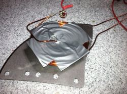
I would appreciate any advice to get this to oscillate.
Power limitation, bummer… Considering the psu has both 12+/- outputs each rated to the 18 amp max, could + go to the choke, and – to the mosfets? Thus possibly resolving some of the limitation of dividing only one 12v source? (fyi-i am a novice if the questions dont do enough to signal such)
🙂
Farhad, The choke in the induction heater is to separate the high frequency oscillations from the PSU, and to limit the current flow. This also helps ensure you get a good sine wave output. When oscillating well, the frequency should be pretty close to 1/2pi*sqrt(LC) where L is the combined inductance of the two halves of the coil. Adding a load will also alter this. The simulation does not take in to account many factors such as the specifics of your PSU, or parasitic components.
Joseph, Yes 12V will limit the power. You may not need the additional regulator, but I would recommend it as it helps protect your transistor gates and ensure smooth operation.
I have ordered the parts to spec’s in the artical, and while waiting read the artical and comments several times over. I have a much better understanding of the process now, but a few questions remains. With the old cps I am using (310w) I have a 12+ output rated to max 18amps. I plan to connect this to both the choke and mosfet inputs. Will this voltage severly limit the work coils heating? Also, since it is a cps and likly already regulater, will I still need to consider the lm4812 mentioned in the comments section? Past and future thanks!
hi,I build it by irf3205 VDSS=55V and it work good
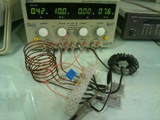
at 10v power my coil diameter is 6cm and 330n capacitor it resonant at 150KHz but not hot
I ask you to explan why we use choke what is the function of choke exactly ? and why in simulation in voltage 4V diod and mosfet switch? i eliminate L2 and power2 in simulation and see it resonant and voltage being up per second why?
what is the function of resistanse (its effect on speed of starting resonant)? why frefuensy is not egual to 1/2*pi(L*C)^0.5?
Vgs does not determine Vds when the gate is saturated (such as above 10V). The voltage applied to the gate here is 12V, but the voltage from the supply for the rest of the circuit is 30V. When a ‘Tank Circuit’ (inductor and capacitor in parallel) is pulsed, it will resonate at its fundamental frequency. If the Q factor of the circuit is good enough (there are not significant losses through resistance etc), then there will be a resonant voltage rise in the circuit. The peak voltage here will be about pi x input voltage which is why we get about 90V from 30V input.
The power actually builds up in the LC tank circuit. Once running, the current drawn from the supply will be less than what is actually flowing in the induction heater circuit. Try the simulation in the article to see this.
How is it possible that the applied 12 Vgs on the MOSFETs gates cause a 90 Vpk-pk on the scope? I mean Vds will never be higher than Vgs, right? But (90Vpk-pk) / 2 = 45Vmax. 45 Vmax / SQRT(2) = 31.8 Vrms. Where 31.8 Vrms equals ~ the input voltage of 30V from the PSU. How can you ever reach a Vrms higher than the applied Vgs on the MOSFETs. Please do explain as I wanted to use a power supply of 45Vrms to crank up the power!
Thank you for your help and time.
As long as the water is not contaminated with significant amounts of electrolyte (like in salt water), then the length of tubing should make the total resistance so high that any current flowing in the water would be neglegable.
2n3055 is not suitable. Use the MOSFETs mentioned in the article.
Hi I would like to know if it is possible to use two 2n3055 transistors
Thanks
Mii Yeti
(1) Failure of my oval shaped work coil leads me to make 2 circuits which I have to use simultaneously. Do I have to arrange separate PSUs for chokes in both circuit? (2) Will there be some sort of electrolysis effect if the cooling water from one work coil flows into the other? (3) Is there any way which can indicate resonance…. something like an LED or a neon bulb?
Good day!
(1) After many failures, I decided to start all over again. I made a new work coil with 2mm solid copper wire 5+5 turns. For choke I used 1mm wire, 16-18 turns. For MOSFETs 12v-2A supply and for CHOKE 19v-4A (laptop) supply. The combination worked nicely, the sample got very hot in just 3-5 seconds (not red hot because of only 4A supply).
(2) The results encouraged me, I made another W/coil from 4.7mm outer dia/2.7mm inner dia copper tubing. I started with 3+3 turns and coil shape round unlike the one shown in post no. 4862. Power supplies remained as above. The load remained cool and the w/coil became warm without water circulation. Modified the turns of 1mm wire choke — No improvements. Changed the choke to 2mm wire 7-8 turns —- No improvements, additionally the MOSFETS are becoming pretty warm.
I wonder if this circuit can operate with a voltage of 220 volts? I know I’ll have to change the components, but I wonder if the circuit is capable switching at higher voltages. I need heat a billet steel 15mm in diameter.
Links to all the available parts are in the article. If you add them to your basket, you can get a shipping price calculated automatically.
Just obtained 24vdc, 15 amp power supply.
. . .Please furnish me with the type and number of torroid coils (L2)you recommend and sell to max this power supply.
And the size, number, voltage and type of caps I will need, and the two transistors (T1 & T2), you sell.
. . .I will want 4 Zener Diodes, plus 6 resistors (R-1 & R-2).
. . .I have the heat sinks for the transistors and for the caps. I assume the Voltage Reg (7802?) is readily available locally.
. . .I would appreciate the material costs and the shipping to zip code 59711, USA.
I would best like an email in responce to any necessary questions regarding this request.
. . .Thank you, charlie.
@#4966: Why do you want to use 230Vac? It is all about amperes for induction heating and high frequencies to stimulate hysteresis in the workpiece. When Xc and Xl (reactance of capacitance and solenoid) are the same you are in resonance and the circuit acts as a short (for this parallel circuit it does). So if you would have 0.4 Ohm resistance on the copper wires, you would have 330 / 0.4 = 825 Amperes with 250Vac rectified. Why not taking a 12 volt power supply instead? Then you would have 30 amps. That is quiete alot. Or take a 24v power supply and you would have ~60 Amps!!
You can’t use this circuit at those voltages. You would need a different, more complex setup which is beyond the scope of this article.
one problem if i rectify 230 volt straight from the net (its 230 x 1,44)it will be 330 volt DC a simple regulator (7812) will go to max 30 volts…and how much volt wil there be on the diodes…?
the other side…..used a lot of solder tin 🙂
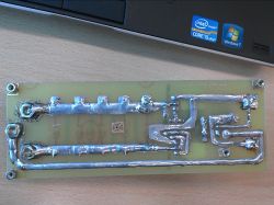
It would heat it, but I would not call it a furnace. You may even struggle to get it red hot. Once such a large load is placed in the coil, the current draw will rise significantly, and quite probably need more than 5.5A. We will however post a new project in future which allows for higher power levels.
I own a 12 volt, 5.5 amp dc power supply. I would like an induction furnace that could heat 25mm round or square stock. Is this power supply sufficient to accomplish this. . . 62 years ago I fell off the ‘Wheatstone Bridge’ in college..hence my need for assistance. thank you.
Looks nice. DId you etch your own PCB? You may want to reinforce the PCB traces from the caps though as they will be carrying a lot of current. You can see the regulator diagram in post 4649. The zeners would just go between the gate and source with the cathode to the gate
this is mine…..now want more power !!
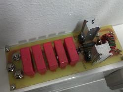
I used HFR3205, and it works good…..what kind of regulator and zener you maen or think is possible…..can you make a schematic….
thanks
There’s nothing else I can suggest.
(1) Noted. (2) Any comments — why didn’t my circuit worked with two supplies?
Well the STP30NF10 used here does fine even with 30V input if you have a regulator and zener protection on the gates, but you can try other transistors if you want.
Thanks for your usual prompt response.
(1) Yes, I had a common ground when I used 2 supplies.
(2) So changing the MOSFETs to higher rated voltage can withstand the initial spike?
If i use a fets who has a voltage of 600 and 50 Amps , can i use it from the net after reverse it from 220 volt to DC, the IN4007 and caps are up to 1000 volt…BUT what wil happen to the gate power of the fets…?
Okay thank for the reply..
Yes, use a single 24V supply and regulator for the gates. When using two supplies, did you create a common ground? You could change the MOSFETs if you like, just choose good ones with low resistance and high speed.
Thanks for your swift response.
(1) Okay, I shall change to 24V 30A + 7812 but for the sake of learning, I want to understand why my circuit did not worked with 2 power supplies?
(2) The simulation helped me a lot. Thanks for the newer simulation with single supply. For load, I coupled another inductor L3 (1uH) to L1/L1b and connected a load in parallel to L3. The maximum readings (during the initial spike) I got with 200 Ohms……V at drain 200V, I at drain 24A, V at gate 14V, I at gate < 1A. So how about changing the mosfets to 300V/35A to ensure protection against the initial spike?
The link is directly to an asc file. You can click to view it, or right click and save it to your computer.
The simulation does not include any load and is not accounting for the losses in the system which is why it only draws a low current. You should observe the voltage on the 30V supply. During the first moments it will drop very low which could prevent oscilation in a single supply system if not accounted for. You should also consider the initial voltage spike as this could blow any of your components. Try this simulation. It will not oscilate becasue the PSU has too much internal resistance. Run it, you will only see DC, then alter the resistance to something lower and you will see it begins to oscilate.
Yes, add the regulator and zeners as suggested.
Hi Richard.
(1) The link for simulation opens NETLIST in another window which deceived me that you are providing netlist instead of asc file. Anyway, I have opened your asc file and compared with mine which wasn’t simulating. The main difference was that you used 2 power supplies. Now my simulation results are same as yours.
(2) In the simulation, I noticed that the circuit (except the capacitors and inductors) is drawing less than 1 Amp. So, I physically connected 12v-2A supply to the MOSFETs and 12V-30A to the choke. No oscillation, one MOSFET burnt. Maybe no oscillation because MOSFET burnt. Am I wrong somewhere? I plan to use 24v-30A for the choke and 12v-2A for the MOSFETs.
(3) Mosfets IRFP150 + 6 x 330n Polypropylene Caps still oscillating at 12v-30A (but not red hot). Shall I use 24v-30A supply and add 7812 for the MOSFETs?
You can not just replace the transistors with power IGBTs. The saturation voltage of the transistors would be too high, preventing proper switching as explained in the article. A different and more complex circuit would be needed.
Hello i build you heater, and it works ok….Now i want more power….but i hav one question… If i use bigger FET’s / IGBT,up to 600v and 150A (MG150Q2YS40).. Can is use the same diodes to the gate, i think the power over the gates will be more than 20 volts….
Aamer, It is already an asc file. I don’t know why you renamed it. Yes 12V will work but of course less powerful than 30V. As mentioned multiple times, the capacitors need to be quality polypropylene or equivalent. It may oscillate when using other caps, but the performance will be poor. If they are damaged by voltage spikes, that will also prevent proper operation.
Nicollas, Thanks for sharing. Nice build quality.
Charles, please read through the other comments. As mentioned already, brass was only used because it was available at the time. Copper pipe would be better. Yes you can use whatever coil shape you like. However the heating effect may not exactly match the shape as the magnetic interactions and shape of the object will dominate the effect.
> > > > two questions < < < <
1. In a water cooled installation would one still need brass induction coils instead of plain copper tubing?
2. I see where the coil configuration can be modified. So for tempering knives one could have an egg shaped coil allowing 1/4" clearances on all 4 sides. Correct? . . .thank you chas.
ps. great site.
This is the result obtained by me. was very good and oscillates at frequency of 75kHz. Thanks for the help RMcybernetics and friends.
I have limited knowledge/experience of electronics. I am simply following the instructions as well the experience of other fellows. I knew you used 30v 10A. But you also confirmed in post #4698 that the circuit will work with 12v 30A PSU, and Bob was successful (post # 4894). Anyway, I can increase the voltage to 24V at 30A, will it be OK? As far as the capacitors are concerned, frankly, when the circuit is oscillating, I understood that the caps are working fine. I will try again with 24v, if unsuccessful then will check the caps. I renamed the spice file extension to "*.cir" and opened it in LTspice and then clicked RUN icon. If you think I am wrong, can you provide the "*.asc" file??? Lastly, thanks for your guidance.
Lol, the spice file is fine, I really don’t know what you must be doing. You will need a higher input voltage than 12V to get heating like shown in the video (I used 30V). Have you also considered that your capacitors may be damaged, or just not up to the job?
Thanks for your swift response. Okay, I shall change the STP40NF10 to IRFP150 and then re-try with my existing PSU which is functioning quite OK. But, I shall definitely not ignore your tip to change the PSU. By the way, what do say about the 12V 30A SMPS, will it be OK?? Your netlist could not be simulated because LTspice is giving an error "Multiple instances of Flag". Would you please check it. Thanks for your attention.
You are using different components and some kind of DIY power supply. You will of course not get the same results.
As per my results on various turns of the choke, the intensity of heat (as I felt) was almost the same. Of course, keeping the load for more time will make it hot. But, pardon me, my trial load is not thicker than the screwdriver shown in your article, which turned red hot in just 5 seconds.
You should allow more time for your load to heat up. I’ve added a spice simulation to the article just above the troubleshooting section. The STP40NF10 was not in the library so I just chose something else in the library. Run the simulation then check out the collector waveforms and inductor current. The simulation does not include any load, but you can add this if you wish. I’m not here to answer questions on how to use LTSpice though.
Another question: I want to understand the behavior of this circuit and hence plan to simulate it in LTspice. How should I check if my simulation is correct……I mean to say, at what points I should check for the waveforms and what type of waveforms?
Good day Richard…..Appreciate your devotion to guide others. Just for reference, I posted my Work Coil design at #4862 and the choke at #4886. I had to replace one faulty STP40NF10 with IRFP150. Now my circuit is oscillating with STP40NF10 + IRFP150 but the trial load (4mm iron nail) only gets warm. As per your advice, I re-designed my choke with 20 turns of 2mm wire and then reduced gradually 18, 16, 14, 12, 11, 10, 9, 8, 7, 6, 5 turns but no significant change. However, at 9-8-7-6 turns the load got warmer + the STP40NF10 dispersed more heat. By the way, I inserted the load for 5-10 seconds.
This link should answer that for you.
Last question: What is, if any, the difference between polypropylene and mylar caps?
Thank you, I had guessed they werent going to work..wanted to ask before I released the magic smoke out of them
No they wont. That looks like a polystyrene capacitor and judging by the thickness of the wires, it is not meant for high currents. You need to use polypropylene capacitors or an equivalent that is specifically made for high currents. For larger objects you need more power.
Hi…I have been looking for a circuit like this wit a straight forward explanation..Kudos RMCybernetics.
Will the caps (pictured) work with this project.
.003uF 4Kv (302K4M)
I am seeing in my calculations that my project will resonate near 400Khz. And if I am right, not an engineer, would mean I can heat larger objects.
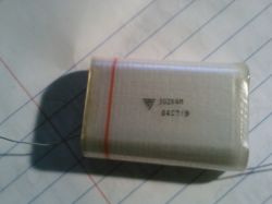
It only becomes an issue if the rise/fall times are a significant value compared to the period of the operating frequency of the circuit. The transistors are switching when the voltage (between source and drain) is almost zero. Just work out what the switching time is as a percentage of the period. By minimising this value, the switching losses are reduced. In this circuit you would probably be more concened with conduction losses due to high currents unless you need it to operate at some very high frequency for some reason.
Is there a ratio of rise / fall times to capacitance values? I’m curious to know the mathematics behind the circuit.
While I can’t comment on every individual transistor model anyone might use, I can suggest that if you use one with longer rise/fall times, you could compensate by using a larger capacitance to lower the resonant frequency of the system.
Since you guys have a bit more experience then myself with induction heating devices, I wanted to ask how well might an MTY100N10E N ch. Mosfet work for an induction heating application as far as the drive transistors? This transistor is rated for 100A @ 100v the on-resistance is quite low as well @ 0.011ohms, the only thing I see that is quite different from the recommended transistor pair, is the switching times (rise / fall) are quite a bit higher, but I suspect that to be normal for such high currents possibly? I’d like to get some feedback from someone with a bit more experience to see if I can use these transistors for my induction heating tests. I’m interested in heating a bit larger objects and a bit faster.
Thanks
-Allen
See the troubleshooting section I’ve added to the end of the article. You don’t tune your induction heater. It automatically works at the resonant frequency. The link I gave you is to a product which will allow you to limit and control the input power so that you do not blow your transistors while testing it. I don’t think adding another DIY circuit is going to help you, as it just increases complexity. Adding 1 turn to your choke is going to make little difference. Add something like 20 turns. I really do not think there is anything else left to suggest to you. If you are following the article and all the advice, but it is still not working, then you must have faulty parts, wrong connections, or a PSU that is not up to the job.
I increased the size of choke L2 from 8 to 9 turns. It increased the amperes and blew off 30A fuse of my PSU. Now, as per your suggestion to introduce Power Pulse Modulator, I have just finished the "SQUARE WAVE SIGNAL GENERATOR WITH PULSE MODULATION" for my Induction Heater. I am confused how would it withstand heavy amperes. Please guide me how should I use it so that I can tune my Induction Heater.
Your PSU is not able to meet the peak current demaned by your setup. When you first connect power, there will be a surge of current which is mostly limited by your choke (L2). Use a bigger choke, and add some large capacitors to your PSU.
Hi. I did exactly as instructed here and used all the same components but mine doesnt seem to work. Only one mosfet gets really warm. The PSu which was initially set to 15v and 5 amps drops to below 5 volts once the control circuit is connect. Any idea on what seems to be the problem? The PSU is rated at 30V and 10A. Thanks.
Yes, I think you will need to experiment with what works best with your specific PSU and heating coil. You could also try using a Power Pulse Modulator between your PSU and the induction heater circuit. This would allow you to vary the power to the heater. You woild set the frequency settng to a low value like 20 Hz, then you can adjust the duty setting from 0 to 100% to give you a 0 to 100% adjustment in heating power.
Do you mean I should increase the number of turns in my choke shown in post no. 4886? How many more turns do you suggest? How do we find out the matching coil size other than actual trails?
By the way, does every new circuit we build (with same parts) needs different choke setting (inductance)?
I still think you need a bigger choke. The huge inductance of the transformer winding is allowing it to oscillate, so you just need to find the right iinductance value for your setup. When powering up the induction heater, I would suggest that you do so without any metal within the coil, then add the metal after.
You can see the work coil at post no. 4862.
You can see the circuit at post no. 4894.
The iron rod was not a particular one. I tested on an iron nail, an 8mm iron rod and 5mm rod…..all three got warm.
Frank, The diagram is ok. You should only use one regulator. The way the connections switch on and off the gates is described in the article.
Aamer, Show us your work coil and iron rod.
Okay, I have made the test replacing the choke L2 with a low power transformer. Initially, the work coil became warmer and warmer so I circulated water in it. Finally I was able to notice that the iron rod inside the coil has become warm.
However, when I replaced the transformer with the choke L2, the MOSFETs became hot quickly. And nothing happened to the iron rod inside the work coil.
By the way, I haven’t yet introduced zener protection for the transistor gate.
RM, Thanks for the reply regarding the voltage reg. I did notice the diagram with the 7812 but thought it was imcomplete because the drains of each mosfet still feed back to the gate of the other after the voltage reg. I was wondering if this should be done with two regs, both right at the gate and after the diodes? Just not sure how this configuration will work?
Place something metal in the coil and see if it gets any warmer.
I have replaced the MOSFETs. And also have replaced the choke with a low power transformer. I do not have an oscilliscope so how do I know if the circuit is oscillating or not.
Iron based metals heat well because of hysteresis losses and conduction losses. Metals like copper and aluminium can be more difficult to heat partly due to higher conductivity.
The magnetic field is strongest at the inside edge of the coil. The skin effect also forces heating to concentrate on the surface of a material.
Hi,
Just an experimenter in electronics but think I will have to try this! Two questions
1) I see people generally heating iron or steel. Are there other common materials which might heat even more efffectively and is there a simple answer to predict which materials will heat well (I am guessing high permeativity, high hysteresis?)
2) Is the heating effect uniform throughout the interior of the coil? Or is it concentrated more towards the center or periphery? Lets say you were trying to heat the water in the copper tubing, would a hollow metal tube fit to the diameter of the coil work?
Well I guess that is more than two questions, In any event thanks this looks like a great project.
See post #4649 for a diagram including a regulator. Yes, the capacitors in your induction heater must be low ESR otherwise resistance losses will soon heat them to destruction. Yes, copper is better due to lower resistance. Brass was used simply becasue we had some available at the time. I’ve since built one with copper which I will post later, but I did not see any noticable performance difference and the heater coil still needed to be water cooled.
Couple questions.
1. Obviously if you push the voltage up, the Mosfet gate must be protected with a reg, but where are you putting that because it appears you are shorting the drain and gate??
2. You mention using alt caps for this. Would I need the lowest ESR caps possible? IE poly or film/foil caps?
3. There was a question above regarding tubing choice. It would seem that copper might be better for this. Is that accurate? Why did you select brass?
You should just replace both MOSFETs in your induction heater to be sure. Yes, pretty much any low power transformer will have enough inductance to limit the current to a couple of amps or less. It will be useless for significant heating, but allows you to test if it is oscilating without blowing components. You may also want to add zener protection to the transistor gates.
Before replacing the choke I checked the MOSFETs and found that my all the pins of my M1 are short. For M2, while connecting the negative probe of multimeter (on diode checking mode) to the center pin (DRAIN) and the positive probe to the left pin (GATE) the multimeter beeps for continuity. And touching the positive probe to the right pin (SOURCE) the multimeter shows 490. And if connecting the pins vice versa then no continuity. I can understand that M1 is bad but not sure about about M2.
As for replacing the choke with an ordinary transformer, do you mean I can use secondary winding of any 220->3v, 6v, 9v, 12v transformer (less than 1 Ampere)?
Try replacing your choke with something with huge inductance so that power is limited significantly. You can use an ordinary mains transformer for this. Just use an output winding as the choke. If it still wont oscillate, make sure you don’t have a dud transistor or diode somewhere.
I have assembled the parts listed below as shown in the photo:
MOSFET – STP30NF10 – 2 Pcs with Heatsinks
DIODES – 1N4007 – 2 Pcs
CAPACITORS – 330n x 6 (1250v)
RESISTORS – 240 Ohms
CHOKE L2 – SWG 14 (2 mm) Copper Wire 8 turns
PSU – 12V 30A regulated, smoothed
I switched ON the PSU for a few seconds, the MOSFET M1 in the photo started getting hot so, I switched OFF.
Need your further assistance, please. One thing, the PSU is connected thru 50cm wires.
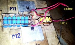
Daniel, Andreas,
Make sure the supply to the resistors is regulated and smoothed with a capacitor.
Check that your supply is capable of providing the peak current demanded by your coil.
Decouple the supply to the gates by placing a capacitor from 12V to GND while keeping the connections as short as possible.
Place a 12 to 15V zener diode between the gate and source of each MOSFET (cathode to the gate). This can help reduce noise and protects the transistors.
I cant get this to work…
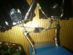
the non of the conections or heatsinks are touching.
Here is a picture the wiering, are the diodes the right way, have i solderes them to the right legs on the transistors?
Hi
I have tried different size inductors for L2 and it dosn’t really seem to do any difference for the high frequency that is superimposed on the sinewawe.
The biggest inductor I tried was about 40mH, The voltage in the LC circuit went down, but other than that there was little difference.
I also have problems with the voltage spike in the beginning of the sine wawe being about double the voltage of the top of the sine.
Looks ok, but dont let your heatsinks touch together or you will just be causing a short circuit. Fit a capacitor to the output of your regulator too, that will help smooth out any noisy power line. Something like 330uF or more.
hi,
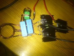
can anyone see any thing wrong whit this setup?
this is my second inductor, but i am having the exact same problem…
mosfets are getting real hot real fast?
any ideas?
Looks ok. You can try the caps you have but they may overheat quite easily.
Just to have everything in perfect order, here is the choke which I made with 2mm, SWG no. 14 copper enameled wire. Is it OK?
The 28 x 68nF capacitors which I have mounted at the end of the work coil are MYLAR capacitors rated 400V but they are small size about 12mm x 8mm x 3mm. I wonder if they would do the job or should I replace them.
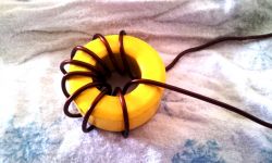
The wire i used vas about 1,5 mm2…
do you think that`s the problem?
Are brake lines stainless steel? That has a high resistance, as do thin wires. You need to use thick cable or pipe that is highly conductive.
Hi.
I buildt a Induction heater.
I used the same components as you, so you know the specs off the transistors, capasitors, voltage regulator, resistors and diodes.
My induction heater will not heat any thing and the transistors heat up really fast?
They are mountet on heatsinks…
what can be wrong here?
My coil is maked from brake lines, i have allso tried whit mutch thiner wiers…
Would it help if i uploaded a picture?
Grant, The radiator is a modified CPU cooler from a computer. I think this one came from an old DELL PC.
Steve, The voltage rise in the circuit will be about 3.14 times your input voltage. But your capacitors voltage rating should be significantly larger so that they are not being pushed to their limits. I would suggest using one rated for at least 6 times your input voltage.
What voltage should the 2uf capacitor be rated for?
15 V or 90 V?
where did you get the radiator from?
Try using a much much bigger choke, and regulating the voltage used to feed the gates. Make sure the supply to the gates is well regulated and filtered.
Here is a picture of the setup, I did not have my good camera here, so I can take a better picture later if that helps.
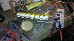
Hi
I would like to make one that is about 500W
Parts I have used:
IRFP4768 transistor
1N4007 diodes
240 ohm resistor
12 turn work coil
7×0,15uF (total of 1,07uF) low ESR capacitors.
About 2mH choke
The powersupply is a 10A 30V lab supply.
I use quite a big capacitor bank on the output of the powersupply to
help it cope with the current surges.
The problem is that when I crank up the voltage the transistor gets
worm and shorts out (drain/source)
I suspect it has something to do with the hairy coil since wave (blue trace)?
I cannot figure out how to get rid of that noice, so i would really
appreciate any help I can get on the subject.
I tried mounting 12V zener diodes to protect the gate but haven’t
dared turning up the voltage again while the hairy sine wave is still
there.
I am on my last set of transistors.
Thank you for sharing sutch a good project with us, and helping
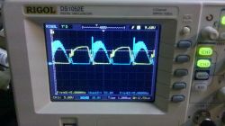
us all out.
A straight bar is ok, but will need more turns compared to a toroid. Those caps should be ok as long as they are capable of withstanding large currents and high temperatures. You can just link the ends using some PVC pipe as long as the copper is connected together too.
Here is the work coil which I have designed for my application.
I would like to know how shall I join the two ends encircled in red color for continuous flow of cooling water? Do I need to braze them with brass or simply connect them with PVC tube?
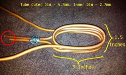
For the choke L2, can a straight ferrite bar be used instead of toroidal core?
For the capacitor bank, is it OK to use 28 x 68nF (400V)?
reg, if the gates are not switched on with a high enough voltage, the transistors will heat up significantly. Waheed, adding a large object in the coil will increase current demand a lot. if you want to limit the current, use a bigger choke (L2).
Thanks for useful information. My circuit consists of IRF3710, 5x330nF/100V caps, 4 Turns of 3mm OD tubing at 12V. Draws 4 Amps. Tried it on higher voltage using 7812 but didnt work – no oscillation. Removed 7812 but with a large object in coil the current shoots up uncontrollably, burning FETs. What could be the reason. Thanks
Just wanted to show the waveforms.
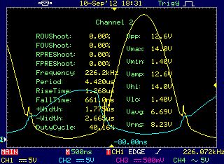
I am very pleased with the outcome of my induction heater.
after many failed attempts I managed to solve the problem and now it works fine.
Thank you all for the help.
hello , do you know what it happen if the gates
becomes less than 12V?
ok ,i will try 25 volts power supply
and greater heatsink , thank you for your fast
answer bye…
See the calculations posted by kevin in post 4817. With a 36V input and IRF540 transistor you are likely to blow the transistors. As shown in the article our 30V input was causing it to push close to the limits of the transistors used.
thanks for your answer
i use mosfet irf 540, use 36V power supply
and separate 12V supply for vgs
10 + 10 turns work coil with 680 nF capacitor 1000V , L2 2O turns
it is good?
Andreas, 6 or 8 will work OK. Using 8 may share the current a little more and therefore not heat up so much. Reg, the temperature of the MOSFETs will depend on the current flowing and the frequency. If the frequency and current is quite high, it is normal for them to heat up. Try using a larger heatsink, or MOSFETs with a lower drain-source resistance.
i make your schematic and it works very good!
thanks
just one question, my mosfets are very hot
why ? thank you for answer
Hello again.
I have ordered 8 capasitors from you, is it best to use 6 like you have on your setup or will it be best to use them all?
Mike, Andreas, The inductor L2 serves as a choke to prevent high frequencies reaching your power supply, and also as a ballast to limit current. The calulations will depend on your operation frequency and desired current. 22V is fine, but you will need to feed the gates via a regulator as shown in a previous post. You should probably use more than four capacitors.
is okey 12 volts
110volts ?mosfet? wat number plees
Hello,
I am going to use a 22V power supply, will i need the 12V voltage regulator mentioned in the diy?
where do i conect it?
Are the Mosfet`s marked so i know witch leg on the transistor goes where?
Hello.
In advance, sorry about my poor English!
We bougth a inductive heater at work a last week it cost about 1500 dollars, and i said that i was wondering about building one myself, so all the guys i work with laught at me and said i could not do it…
So i desided that i had to do it to shut them up by building one! 😉
but there is a few problems…
I`m really not a expert on electronics but i have a mild understanding of it so i think i understand most of the shematic you have drew, exept on the right of the shematic there is someting called "L2".
Can you maybe try to explain it to me?
And the second question:
I have a 22V power supply, If make the inductor just as you have shown in the first part of your DIY, exept i use My 22V supply instead of 15V, the Diodes that you used on the "phushing it further" part of the DIY, the thicer brass tubing and maybe 4 capacitors (or do i need 6 on 22V allso?)
Would this work???
I thing its great that i can buy all the parts from your DIY on your page!
Best regards!
That’s good avice, A: is there a calculation that I can use to determine the inductance for L2 based on the inductance/resistance of L1? Im using 3/8 inch copper pipe.
B: do I stll need a 12V regulator in the circuit if I’m using a single 12V supply to drive the whole thing?
Nicollas, Mike; Use the diagram in post 4649 that includes a voltage regulator. Use a bigger choke, and place a large capacitor parallel to the PSU to help it cope with current surges.
Ok, great,one more question. I’m using your same circuit and I’m using a 12v 16.7A switching supply is this going to be a problem? I hooked it up and seemed to fry my diodes. I’m using a nte2396 FET with enhancement mode. I ordered the ones your using to see if that’s the problem. it also makes my supply go into protection mode, almost like the supply saw the curcuit as a dead short, I’m hoping it’s the transistors, or perhaps I need a bigger work coil, any help?
swapped for new 1N4007 diodes and still does not work, the voltage drops to 12 volts to 6 volts, and does not oscillate.
‘m using 220ohm resistors, it interfere in the functioning of the circuit?
No. The resistance of the coil would be too high. The losses in the coil would cause it to get very hot and waste a lot of power. Copper is the best material to use. Brass was only used here because we had the pipe in our workshop and it was small enough for making this simple demonstration.
Can stainless steel be used for the work coil?
wellington, I have no idea what you are talking about. Nicollas, I do not really understand all you wrote either, but it sounds like your circuit is not oscilating. If you are also using different diodes, it could be because they have too much voltage drop which prevents the transistors from being switched.
I set up a circuit like this.
but he is not working.
one of the mosfets is very warming and the current is very high.
put 12V but the current one seems Curco circuit.
aumeitei as the number of windings L1 and L2 no more works. nothing changes that.
I’m using mosfet IRFP250N
what might be happening?
my source is 12V/20AMPS.
thanks for the design
I did 12 volt and perfect design
I am interested in a dipocitibo de24volts acer 110 volts and 220 volts
mofet which I can use or would have k k using thyristors and the condenser capacities
thanks for the design is very cool I worked for one time and I’m interested in Majorcan efficient voltage for faster heating
Hans, Most losses will come from resistance in the components. Mostly in the coil in this case, but losses in the capacitor are not insignificant. It is important to use capacitors with a low ESR. You have things a little mixed regards to altering frequency. Increasing either inductance or capacitance will lower the frequency. At higher frequency there will be more losses in the capacitor dielectric, and also in the coil due to the skin effect. The skin effect would also mean that at high frequencies the heating would be concentrated in thinner layers on the surface of material sample.
Justin, Yes, the voltage rises as described in the article would mean that exposed terminals or the coil could have high voltages present. You should avoid letting the heated object touch the coil as it could short circuit and damage your transistors.
Is there a risk of shock with this circuit?
-risk of shock by touching the element that is being heated in the coil with another metal rod? (or is it electrically isolated?)
-risk of shock/spark/dangerous short by touching the element to be heated to the coil?
-risk of shock by touching the brass coil?
-anything else i might not be thinking of?
Hi
I was thinking about Kevins post.
I’m not an EE and can be totaly wrong but :
In a self oscillating circuit like this the freqency tend to be where the capacitive and inductive reactance equals out eatch other ie: the voltage and current is in phase and the power factor is close to 1 .
If this is true, then the losses must come from resistive load ie the resistance in the coil and copper would probably be a much better material for the coil ?
Since it is a self resonant circuit, changing cap or coil would alter freqency : more inductance or less capacitance = higher freqency and less inductance or more capacitance = lower frequency.
Now to my question :
If I am right, what benefits would there be if I used higher (or lower) freqency?
Would I get higher effeciency ?
If I am wrong, where did I go wrong?
Hans
It looks OK. Is there any reason the tips cant be closer together, or even placed end to end? Separating the two halves of the coil means that the field in each coil will oscillating in strength, rather than alternating polarity as you would have when the coils are together. You would really be better off having two separate circuits and coils as it would be most effective.
Comparing my last proposal of work coils – B, C, and D, what do say about this modification?
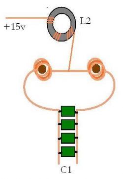
It depends on how fast it is rotating, and how large the metal parts are.
Thank you for your time to answer this question…Is it possible to make an induction heater that would heat pieces of iron that are welded to a rotating drum as the individual pieces pass over the induction coil with say, 10 pieces of iron distributed around the circumference of this drum, and be able to heat the drum by this method quickly to around 460 degrees, with a wattage of in excess of 3000 watts? Again thank you for the time to tell me if I am barking up the wrong tree.
John
Grant,
You need to work out the values for yourself, we can not do your project for you.
I would like a to make one that uses no more than 12V and 10A what size of capacitors and resisters etc. do I need.
I need it to vaporize gasoline or diesel fuel in a metal pipe thats about 1/4 in ID max. (Goal temps around 140-200 F)
I’m very green at this I need a lot of help with this science project
Thanks for your comments Kev.
Aamer,
a) The capacitors voltage rating just needs to be larger than the voltage they might be exposed to. Remember to account for the resonant voltage rise.
b) A would not be very good due to low coupling, but the others will be ok. Copper wire is only going to be ok at low power levels. Litz wire would be better, but water cooled pipe will be best.
Hey Guys,
Ran some calculations on both of your heaters. In the first one, at about 200kHz, the inductor should be about 1 uH. Realize that the peak voltage that is ringing in the tank circuit is going to be pi* supply voltage, in this case about 47v. This yields a peak current of about 39 amps! (27.5 RMS amps) Given that 2mm brass tubing was used, this give the cross sectional area of about 3mm^2, and since it was tubing, most likely about 1mm^2 for current to flow, the approx. size of an 18 AWG wire. Passing 27 amps through 18 gauge wire would heat the wire up to well over 90C if it was pure copper, so being brass would increase the losses and it shows in the photo where unloaded the circuit is dissipating over 40 watts! no wonder the coild was starting to soften.
The second circuit is a little better. It is using 1.98 uF of capacitance at 133 kHz. This gives us a coil inductance of about 0.723 uH. This yeilds a current in a tank of about 105 RMS A. Even though the tubing is larger and cooled, the losses before inserting the load was already at 210W.
That being said, the current ringing in the work coil needs to be reduced. That can be done by one of two means, increase the inductance or reduce the capacitance or both. i(t)=v(t) sqrt (C/L). This is derived by setting the reactive power formula equal to one another and solving. KVAR = V^2/Xc = I^2*Xl.
I would redesign to limit the resonant current in the work coil to be much lower and then see what quiescent losses are. Then put in your load. I bet the time to temperature would be greatly reduce because more power is going into the load and not be wasted in circulating current loses.
Kev
Here are the four designs of work coils.
Ah yes, another question: Does a solid copper wire coil would do the job?
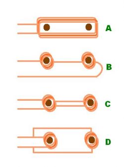
I am planning to make this simple Induction Heater for heating Catheter Tipping Molds. Please see the attached picture of the mold for your reference.
I plan to heat two molds simultaneously. Mold diameter 1/2" and distance between the molds would be 4". I have 2 questions:
a)Is it important to have 1000v capacitors? What minimum voltage rating would be OK?
b)The second picture shows 4 designs of work coils. Which of them would be more efficient to heat both the molds.
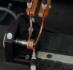
wellinton,
I do not understand you. If you are using an electronic translator, make sure to use good punctuation and grammar for an accurate translation.
irf150n MOSFET can be used, or income tax or 54n 64n
tanbien the iprf250n
for use in parallel bariums
thanks for the info
my question is if I can use this circuit to 24 volts from a battery or 110 volts i also used to reduce a source is 24v 0 30v please ci there is a change in the circuit please give me
ce can also use more parallel trancistores
Hans,
You would also need a very large smoothing capacitor, but it could work.
whisk,
If your solder is melting so quickly it is probably because your wire is too thin. You need to make the coil from very thick wire or copper pipe.
I am trying to build a small version of this using 12v power supply but the solder used to connect the coil to the capacitors keeps melting. Any suggestions. I believe the circuit is working but I can’t be sure since it only stays on a few seconds before the solder melts. Perhaps something else is going wrong. Should the coil be getting this hot?
Hi
Would it be possible to use a welding AC “buzz box” whith a suitable bridge rectifier as a power source ? ( no load voltage 57 V and 25 V at 100 A)
Or maybe a inverter welder?
I wan’t some type of transformer etc since I’m not to fond of hooking up the mains 240 V to a barbed wire !!!
Hans
You would need some type of interrupter circuit and then vary the pulse width of the interrupter. For example; You could use one of our Power Pulse Modulators set to a low frequency to supply the power to the circuit. Adjusting the pulse width setting would proportionally adjust the power in the heater.
Hi, Is it possible and what would it take to have a dimmer switch controlling the intensity of heat?
The STP30NF10 is used in both versions. We used 4mm brass tube, with a coil radius of 25mm.
which type of FET used in 30v 10A Supply in your second case, and give the dimention copper tube and redious of turn.
It might be possible to parallel some MOSFETs, but you would need to make short neat connections otherwise they may suffer from interference problems.
amazing project. cant wait to try it out. I’ve seen some posts about upping the power with larger caps and higher rated mosfets with larger power supply but is it possible to use more of the same mosfets just hooked in parallel with a larger power supply and caps or would that cause issues with the gates. I’ve seen it done in certain types of sound amps but I’m a little unfamiliar with high voltage mosfets and want to make sure before trying
Dear RMCybernetics, dear users
thanks for this smart and very simple way of inductional heating. I tried it and eventually it worked very well. We can heat things up to 350°C and higher.
At first we had problems with the MOSFETS getting hot and also switching through at a certain power voltage level (around 8V). So we couldn’ t get any more then 40W of heating power. Then we discoverred that the wires we used to connect the SOURCE to the ground were simply to long and at the high frequency they produced lot’ s of noise. So we decided to use only one thick wire as connection to the ground of the source and part it short-wired to the two MOSFETs. Now we still got some noise on the GATE but it works very well (15V, 10A).
Greetings
MrLeeh
Benjamin,
Maybe it is the 19V supply. Make sure you use a regulator for the gates as shown in a previous post.
Chris,
Yes the choke will limit the current, but only as long as it is oscillating. You should work based on the impedance of half the work coil.
Hi there. I built a smaller induction heater following as closely as I could to yours, and after a few unfortunate accidents, i got it working and loved it. I am now upsizing to a 110 volt version from wall power rectified through a bridge and a transformer with rectifier for 12 volts to the gates. My question is can I solely use the choke to limit current so that I could have a one turn work coil if I wanted, and if so, do I add that impedance to half or all of the work coil as it is center tapped. Thank you for your great work
RMC, I have managed to reproduce your induction heater using the same components and circuit, but mine isn’t working. I powered it with a 19V 4,5Amps laptop power supply. Actually, all the voltage is shared between the two resistors and it’s like no current flows in the control circuit. Do you have any idea about where the problem could come from ?
David, yes.
Hampus, Both. The first version uses the 40V ones, later when more power is used, the 1000V ones are used.
Which one of the diods are you actualy using? The 40V or the 100V?
can you use 12 volts for this project?
Your MOSFET needs to be able to withtsand the peak current. Measure the DC current your coil draws from your supply whehn you apply 120V. I suspect you need more turns on your work coil and choke.
DISCULPA YO HE CONSTRUIDO UN TU CIRCUITO PERO NECESITO MANEJAR 110V Y 25A, PERO CUANDO CONECTO EL CIRCUITO A LA FUENTE LOS MOSFET EXPLOTAN, LOS MOSFET QUE USO SON DE 600V Y 40A.
AYUDAME POR FAVOR ES MUY URGENTE
SORRY I HAVE BUILT A CIRCUIT BUT I NEED YOUR DRIVER 110V and 25A, BUT WHEN THE CIRCUIT CONNECTED TO SOURCE THE EXPLOIT MOSFET, MOSFET THE USE THAT ARE 600V and 40A.
PLEASE HELP ME IS URGENT
Yes, it would seem that you just have DC flowing at low voltages
RMC,
What is odd is that the circuit has very low impedance at low voltage (1-2 volts) and normal impedance at 12 volts. This is using the same circuit and supply in both cases.
The only difference is that in the 12 volt case I immediately apply the full 12 volts via a switch instead of hooking up the supply and turning up the voltage.
Using my low amperage supply I was able to see that the harmonic circuit wasn’t kicking in until about 5V.
My guess is that at low voltages the harmonic L-C system isn’t being driven and the DC load is passing through a single mosfet through the coil. In this case the impedance would be very low. I have observed just a single hot mosfet in this odd low voltage scenario.
ad,
You can reduce C, but you will need t make sure that the remaining capacitors you have are able to take all the current. The advantage of using lots of capacitors is that the current is shared between them.
Eric,
What you describes just sounds like it is due to the limitations of your PSU. Remember that voltage and current are directly related and will be affected by the impedance of your load. If your PSU shows low volts, and high amps, this indicates that the impedance of your circuit is low and your PSU is dropping the volts to keep the current within its ratings.
I’ve noticed some interesting behavior with this circuit and I am curious what you think. I used all the same components (The coil is similar and the caps are similar, same mosfet, diodes and resistors (I did use a 124 ohm resistors as well, with similar behavior)).
Using a 30V 30A supply the circuit pulls a lot of Amps (15 to 30A) at a very low voltage and the supply simply can’t increase the voltage beyond a few volts. Using a 25V .5A supply the circuit draws power at a low voltage, but I can increase the voltage. At about 5V (according to the analog meter on the supply, could be different given the load) the resonant circuit kicks in and we get a beautiful sine wave on the resonant circuit (but minimal heating).
Using this I went back to the large supply. I connected a switch between the supply and the circuit and set the supply to 12V. Flipping the switch (providing a near instantaneous 12V) drove the sine wave just as before (now pulling a bit more current as the supply could handle it).
So there seems to be some issue at low voltages. It may explain why @joco was getting ‘amps like hell’ at low voltages.
RMCybernetics,
I really like your coil design! I’m working on a project where I need to have a tank that resonates at about 1 MHz. Do you have suggestions for modifying C1, L1, and L2 for that purpose? As long as the FETS can switch fast enough the rest of the circuit can likely remain the same; but I’m not sure whether I’m better of decreasing C or L to get the right resonance. if you had any references for choosing those values that would also be great!
thanks,
a.d.
hi guys i built this thing and had a little truble
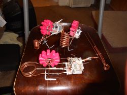
it turned out to be the diodes i was useing (4007) and changed them to some smaller glass ones (don’t know what they are) and with 1.8uf worth of caps it works great!! it was a lot of fun and i built two more to give away all the parts i had got from a broken flat screen tv. they run around 125k and i used IGBT. thanks for the project and a good rundown on it!!!!!!
I used power supply 110 volt 60 A i want to design a circuit i want to know the kind of mosfet transistor and diode and resistors and capacitors so we want a quotation for the material
Chanil’s video…
Check out my induction heater ^^.
http://www.youtube.com/watch?v=iTIHvc6AohI
I had a board made for it. This is one of the tests for it.
Note: the cam can’t read higher temps than 270 degrees celcius. And for my application only 205-210 is required. It reaches about 400-500 degrees celcius in the video.
James,
If you Google the part numbers you will find the manufacturer pdf datasheets. These will tell you which pins provide a particular function. I think it is best you try working this out yourself as you will gain a better knowledge and understanding. You can also check out the section on the site for helping to learn electronics as it will explain a lot about the components and the physics of the electronics involved.
Chanil,
Yes, if you want to limit the current to 1A, then you must increase the impedance of the circuit. Using many more turns in your work coil and the choke will limit the current.
Hi, is it possible to run this on 15V at 1A?
For my application I only need it to achive 200 degrees celcius. But it has to run for days or even weeks at a time(it’s for worlds largest 3d ABS printer). I’m currently using every component that is recommended, but all of them are getting hot… I have already roasted a capacitor(used a wrong one, would it explain the rise in temperture of the mosfets?)In my tests I’ve powered them with a 19V 5A psu(Im using a 12v regulator for the gates). I’m planning to use multiple heatsinks with a small fan to provide cooling.
So to conclude will it reach the required temperture if only using 15V at 1A? Will the components stay cool if it would work? And if not any suggestions?
Hello, Would it be possible for you to show a bit clearer picture of the physical connections of the transistors themselves and to also indicate which pins are what for the electronically challengened among us ?
Nice job. Thanks for sharing Rob.
Just posting to share that I’ve successfully made my own heater using the info here.
Some details of what I used:
– ~.3uH work coil
-12v 30A power supply
-IRFB59N10DPBF mosfets
-4.2uf capacitor bank (100A pulse)
-2mH choke
I posted a Video Response to the original video:
http://www.youtube.com/watch?v=AT_lRjYjzUg
-Thanks for sharing this information.
The current will depend on the voltage you apply, and the load impedance. More turns on your work coil, smaller capacitors, and larger choke inductance will reduce current.
I would like to know a way to reduce current consumption, because my source is 10 amps.
Yes
Will this circuit work properly with a power supply of 12v at 30A?
Your power supply is not able to deliver enough current. You need a bigger supply, or many more turns on the work coil or choke.
HELLO, MY HILL ​​LOOP, BUT WHEN PUT IN POWER SUPPLY CIRCUIT, He behaves like a short circuit and the voltage drops too, IF I DISCONNECT THE CENTER OF TENSION COIL Normalize, BUT NOT THE NOTHING HAPPENS
You can use a single power supply, or seperate ones. If using a single supply it should be at most 15V, or 30V if you use the regulator as shown in another post.
Hello I wonder if VDC power supplies used to feed the coil L2 and Gates/MOSFETS are two power suplies separates.
1. All those factors will vary the performance. The number of turns will determine the impedance of the coil and therefore how much current will flow for a given frequency. Less turns will allow for higher peak current, but too few and the transistors will blow.
The coil diameter should ideally be just slightly larger than the workpiece that is to be heated. This maximises the field coupling and is more efficient.
The capacitor size will also determine peak current. larger is better, but not too large or the resonant frequency will become too low. Physically larger capacitors will have low internal resistance too so they will perform much better. The bank of caps in your picture look way to small for the amount of metal you are trying to heat.
2. You should get a nice half sine waveform. You need to experiment witht the inductor (L2). Try different numbers of turns until you see some improvement. You could also add 15V Zener diodes between the gate and source pins of each transistor to help protect them from voltage spikes.
3. V+ can be as high as you like, just make sure your components are sufficioent to handle the voltage rise in the coil. You will also need to supply the gates from a stable 12V source.
4,5,6. See other answers.
it makes things hot 100 or 200 deg C maybe..
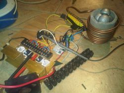
here the other picture
Hi again
I try new coil, new caps, and new Mosfet.
I burtn 5 or 6 of mosfets, it’s happen because I didn’t realize that one diode is sorted so HV directly goes to G pin.
Now I use 30A, 30V power supply, IRFP260, 6A diode, 7812, 7T copper pipe coil,etc.I am quiet happy with the result, but it seems take to long to heat a thing. I plant to melt aluminum with it.
my question are:
1. is coil turn, coil diameter, capacitor size affect heating power, or it just shaping the wave?
2. my wave is slithly different from yours, why?
3. is it ok to increase the V+ to 50V or 90V to increase power (yes I’ll count the mosfet and diode power rate) ?
4. how to trim this to be most efficient? is wave form can determine that? let say clear simetrical wave is most efficient?
5. can we create sinusoidal wave?
6. is sinusoidal wave the most efficient wave for induction heating?
Ohh… I hope it’s not to much..
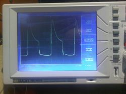
Thanks
I can only suggest you follow the instructions given. If you use other components, they may or may not work. That is up to you to work out.
I sent an email, but I think I should just ask here.
Would these parts work for this project? :
240 OHM 5W 5% METAL OXIDE
1N4007
FDA69N25 N-CH MOSFET 250V 69A TO-3P
FILM Capacitor 2UF 700VDC B32794D3205K
Also, will this circuit be able to handle 55V at 10A (with upgrades)?
-Cheers
Deyan,
It sounds like your capacitors have too much internal resistance (ESR). You need something that is better for high power, they are typically much larger in size for the same capacitance value. There are many types of transistors that may work, but it is up to you to test if the ones you have are ok. I suspect that a high voltage IGBT will have too large of a voltage drop between collector and emmiter which would mean that the opposite transistor would not switch off properly. I used these 100V, 35A MOSFETs which worked well.
Stephen,
I used these 1000V, 330nF capacitors.
What voltage rating are your capacitors?
can i use a IGBT such as BUP203 as the transistors they are reated for 1000volts and if yes are there any difernces in the schematic?
i am usinga 12 volt 10 amp power suply my trnsistor are p50n06 R1 R2 the dides and L2 are the same as yours. Is my suply weak because i cant get i to gloing point and a nother thing my car are burning in about a minute or so they are reatetd for 250-275 volts what shuld i change to get better reasults? Thank you.
Neither. You need higher power.
To get faster heating do i need higher or lower frequency
Tohooloo, C1 can be as large as you like. The combination of capacitance of C1 and the inductance of L1 form a resonant circuit. A larger capacitance or inductance will result in a lower frequency.
Joco, That MOSFET seems ok. Try using a larger choke (L2).
sorry for part number. it’s irfb4615
What is the maximum capacitance for C1.
Martin, If you are not getting nice sinusoidal oscillations, this could be due to having too little, or even too much inductance in your choke (L2). You may need to experiment with different choke designs to find something that works well with your other parts. Your work coil should ideally be only a little larger than the object to be heated as this will maximise the concentration of magnetic flux. If that does not help, add a photo of your scope showing the gate voltage, and drain voltage waveforms.
Joco, I can’t find that part number. Did you make a typo?
FET’s going warm….Amps…up like hell…what is going on?
I used irfpb4615, 4 pcs of 330n capacitor…the rest the same as yours…oh…with a 25V supply.
I’ve tried building an induction heater based on your schematic and it works quite well. However, my heater won’t heat up to ‘glowing point’ (maybe due to my power supply, it’s only 30V, 5A) and, a bigger problem, my FETs tend to become pretty hot. When i look at my coil voltage with a scope it’s way more noisy and irregular than what you are having.
Do you have any clue about what might be going on here?
We don’t have anything else available at the moment. You would just have to look for components with larger voltage and current ratings.
Rmcybernetics, could u recomend some “higher” transistors and caps? I intend to buy some sets from u but I think ill go for the “higher” components if they exist in ur site and with ur recomendations.
This is something else to use this as an induction furnace, but could you recommend stronger caps and transistors and how about the higher voltage power supply? I’d like to buy them from you, rmc
I think 60V is much too low of a voltage rating for the MOSFETs. THey are probably being destroyed by over voltage.
To get hotter temperatures, you need to use more powerful transistors and capacitors, and then use a higher supply voltage.
FQP60N06: I think its 60V, 18A.its chinnese and hardly to find the data sheet.
The large inductor (L2)is behind the CAPs. see my new pic. Thanks for 7812 diagram.
I’ll try another other MOSFET I have, while waiting the the order from RMCybernetics arrived.
BTW what is modification needed to make it a “Induction Furnace” to melt aluminum (700 deg. C)? Thanks
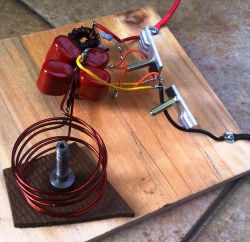
DELETED:
No sending of secret messages in Indonesian or any other language.
Rusdi,
There is also the temperature hazard, and then potentially chemical hazards if components get burned. The scope is not needed, but was useful for seing the waveforms and frequency. The scope ground should be the same ground as your PSU. you can then measure at the MOSFET gate, or collector terminals. If you measure at the collector, remember that the voltage could be much higher than the supply voltage so set the scope accordingly.
Surastyo.
I can’t seem to find the datasheet for that part number. What are its ratings? They are typically set as GDS, but you need to check the manufacturers datasheet. I also do not see any large inductor (L2) in your picture. I’ve attached a diagram showing the 7812 voltage regulator being used.
I build this today and ended with burnt FET. I use FQP60N06. I use 6 turn and 4 x 470nF capacitors. How can it happen?
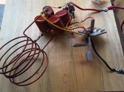
Should I use 7812 to feed Gate? Can you show the drawing? Or wrong pin connection of FET? is it G, D, S if read from front side?
Thanks
I intend to buy 3sets of all the parts from u guys to build this, but I am a newbie in electronics, is there any special considerations to build this other than then current and voltage hazard? And whats with the osciloscope? anything special with the osciloscope, like it has to be grounded in some particular way or anything else? Or any other particular considerations?
Yes you can.
Could I use a pancake coil to make a stove style heater?
The red waveform is the gate voltage of the other transistor.
What is the red waveform on the scope?