
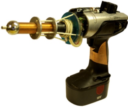
A Hand Held Tesla Coil Battery Powered ‘Plasma Gun’
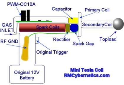
The design for this Tesla Coil is based on the larger battery powered DIY Tesla Coil project but with the aim of getting a much smaller and portable device. A Power Pulse Modulator circuit is used to drive two small high voltage ignition coils wired together in an ‘anti-parralel’ configuration. The output is rectified and used to charge the tank capacitor of a small spark gap Tesla Coil.
| WARNING: This project uses dangerous high voltages! |
| This project is quite old now. Check out the new, more powerful DIY Plasma Gun! |
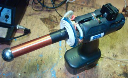
The device is packed into the casing of cheapo cordless drill from a DIY store. This drill used an 18V battery and comes with a charger which made it ideal for the project. The ignition coil driver circuit used takes a direct 12V – 30V input which is connected using the original switch from the drill.
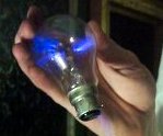
This video clip shows the plasma gun causing a nearby light bulb to light up as if it were a plasma globe.
The high frequency, high voltage from the plasma gun causes the Argon gas in the light bulb to become ionized. This creates streamers that are attracted to the fingers holding it.
The device draws about 6 amps from a well charged 12 V battery which makes the total power consumption to around 72 watts. Unfortunately this low power means the plasma arcs will be limited in size, but since it is hand held that’s probably a good thing. The typical length of the output arcs is between 5 and 7cm

Such a small Tesla Coil inherently has quite a high resonant frequency which in this case is about 500 kHz. This frequency is too high to feel as electric shock but when being zapped you can feel the low frequency component of the spark gap firing rate.
| PARTS LIST | |
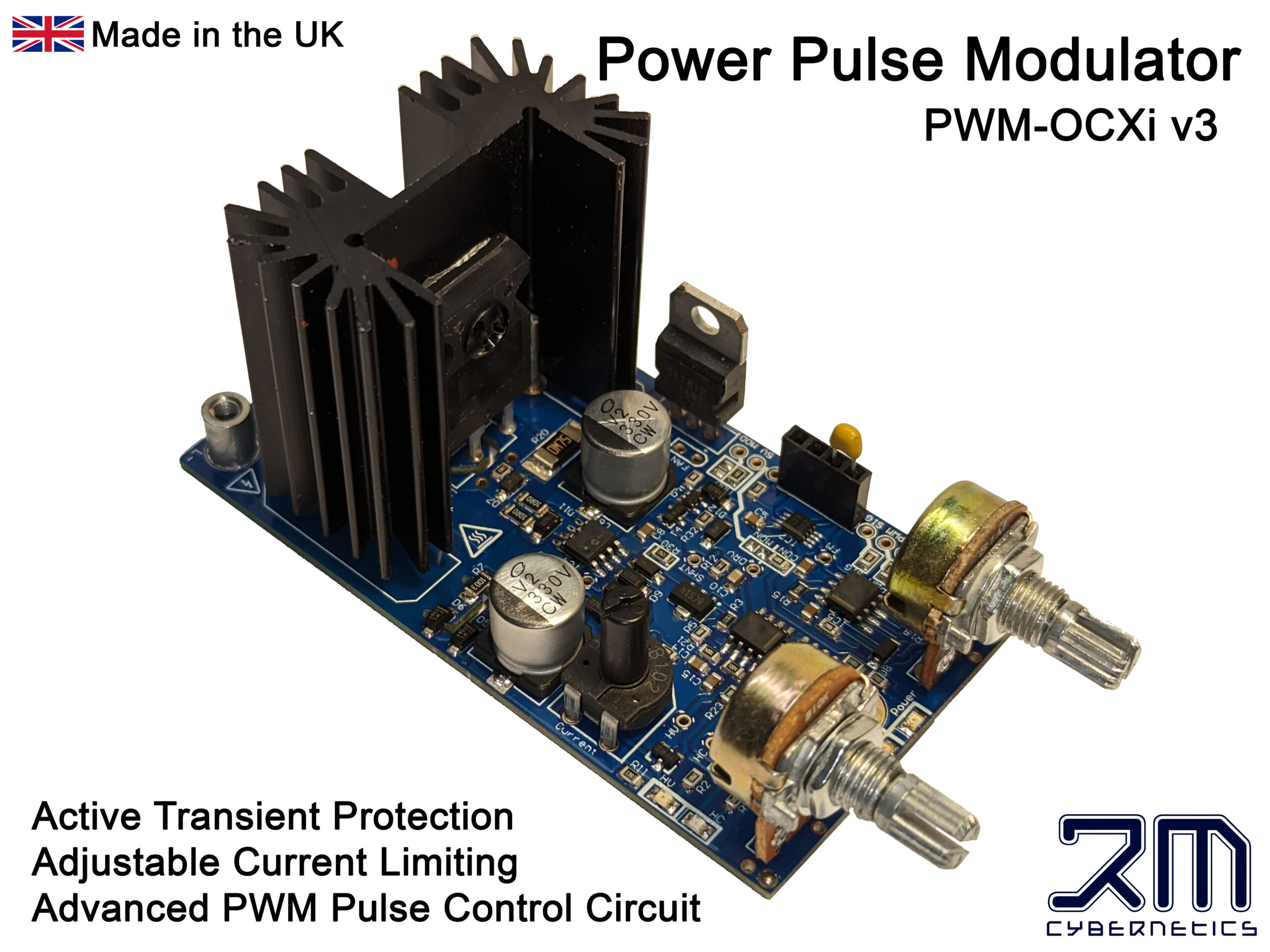
| PWM-OCXi | Drive Circuit |
| SW1 | Trigger Switch |
| Spark Coil 1 & 2 | Small Ignition Coils |
| D1 | 20kV Diode x 4 |
| C1 | 1nF 15kV |
| C2 | 2nF 15kV |
| C3 | Topload Sphere |
| L1 | RF Choke 10uH |
| L2 | RF Choke 10uH |
| L3 | TC Primary Coil |
| L4 | TC Secondary Coil |
| Input Voltage | 12V DC |
| Power Consumption | 75W Max |
| Max Arc Length | 5cm (in air) |
| 7cm (in gas) | |
| Output Voltage (approx) | 50kV |
| Primary Transformer | 2 x small ignition coils < 20kV |
| Spark Gap | Sealed Static Gap. ~4mm |
| Primary Turns | 5 |
| Primary Diameter | 70mm |
| Primary Inductance | 1uH |
| Secondary Turns | 520 |
| Secondary Height | 135mm |
| Secondary Diameter | 26mm |
| Secondary Inductance | 900uH |
| Secondary Resistance | 10 ohms |
| Topload | 32mm Sphere |
| Special Features | Hand Held |
| Portable | |
| Battery Powered | |
| Trigger Activated | |
| Plasma/Flame discharge | |
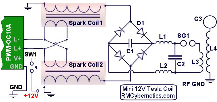
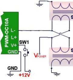
The main driving circuit is a type of pulse width modulation circuit with protection against high voltage spikes. It is adjusted to get the maximum output from the two ignition coils.
The two ignition coils were stripped of the casing in order to reduce the overall size and allow access to the internal wiring. The inputs are wired in an anti-parallel arrangement to help keep the charging voltage high when under load.
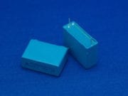
The HV outputs of the spark coils are connected to a rectifier (D1) made from four HV diodes potted in epoxy resin. Connected to this is a small smoothing capacitor (C1) which helps to reduce the ripple in the HV DC output. The tank capacitor (C2) is charged from the HV DC supply via two RF chokes (inductors L1 & L2) which serve to prevent the RF oscillations of the TC primary circuit from interfering with the rest of the circuit.
The previous battery powered tesla coil design needed to be well connected to a good RF ground such as a metal rod in the earth. Without this the output would be limited and the driver circuit would be prone to failure.
 With this mini tesla coil the RF ground connection is made by connecting it to a copper pad on the handle.
The body of the person holding the device is used as the RF ground and the large area of copper ensures the energy is spread out to prevent RF burns.
In most Tesla Coils this would not be safe at all but this device is very low power so there is little risk of electric shock. The RF its self probably isn’t too healthy though!
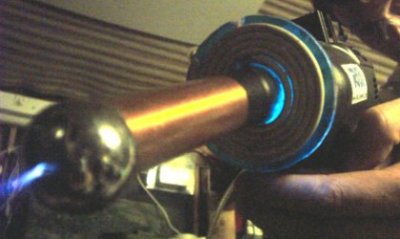
The TC part (Tesla Coil) uses the common single static spark gap and flat primary design for simplicity and size. The primary coil is closely wound around the base of the secondary with several layers of insulation tape preventing flashover.
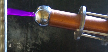
The topload sphere is made from a metal draw handle which has been drilled to allow gas to be ejected from the end. A pipe from this sphere runs down the inside of the secondary and to the back of the handle where it can be connected to a gas supply.
Using noble gasses such as Argon or Neon will cause the output arcs to be forced along the flow of gas. This allows the plasma to be directed in a straight line from the tip of the plasma gun. It is also possible to use butane gas which makes this thing into some kind of flamethrower – plasma gun hybrid. The electricity is conducted along the flame from its tip. You can see photos of this effect on our plasma page.
 Apart from making cool arcs of plasma, this device even transmits wireless electrical power. It can light bulbs and fluorescent lights just from being nearby.
The interference created by this wireless energy can cause all sorts of electronic devices to switch on and off or start behaving erratically. This is because the energy is causing tiny currents to be induced in the tracks and wires in the devices. If a simple circuit had a matching resonant frequency to that of the plasma gun, it would be possible to collect the wireless energy from a greater distance.
 There are several improvements that could be made on this design which could result in a greater power throughput and therefore bigger arcs.
The spark gap is just a single gap which has been seal inside a plastic case for safety and size. This sort of switching will have poor performance due to quenching difficulties and oxide buildup. A solid state version would be better but it would likely be larger and considerably more expensive.
A larger topload would allow for larger breakouts, but it would also need more primary capacitance. The secondary coil is also rather long relative to its width. Ideally this would be shorter and wider.
In conclusion this was a fun project and we hope you find this information useful and interesting.


Yes, the PWM-OCmi will happily drive the ignition coils. They will just have limited continuous power meaning you will need to run for short periods so it has time to cool.
Hi,
I just saw this Project, it’s amazing!
But I would like to know:
Are there any other Power Pulse Modulators I can use for this Plasma Gun instead of OCXI?
Sorry we do not have anything available. This is not really one for beginners either as it involves dangerous high voltages.
Would it be possible to get or buy a more detailed assembly instruction/DIY kit to do this as a science project for beginners? To help learn how to visually put things together, what things are etc. I see you sell the parts individually. Thank you.
Yes, see the table of parts just below the circuit diagram for links to the parts.
can you use the parts from your store for making the plasma gun?
All the information you need is on this site allready. You need to spend some time following the links and reading other articles so that you can gain an understanding of what is involved.
Yes you would need all the components. The voltage ratings etc must be the same or they will be destroyed or not work. THe primary coil can be made from winding any thick wire.
The gas inlet is just a plastic pipe. leading to the dicharge terminal.
alo, where do i get the gas inlet, and could you give me instructions as how i put this all together.
if i buy the drive circuit from this website, do i still have to buy all the components that go on it, like the diodes and capacitors. if i do does it matter if the kV or uH isnt the same as what you said ont he parts list.also where can i get a primary coil, i cant find one on this website.
ok so heres the thing, im a beginner.i dont really know anything about where to get the stuff, hell, im having a hard time figuring out what some of the stuff is!so basically i need you to tell me exactly what im looking for, each part and the specifics on it so i dont get the wong thing.im probably going to try and buy most of the parts on ebay since its cheaper so i need to know what to look up.try to tell me as basically as possible.
It will make a lamp glow. It will not reach 1m as it is not powerful enough. You can buy the parts in our shop. Check the section for High Voltage Components.
Can this plasma gan make a lamp glow? Can such gan make a 1m arc? Can I buy this gan? What about a price?
You can use the code XMAS2K11 at the checkout in our shop to get 10% off any of the parts you purchase before Dec 25th.
sweet,could anything in this project be any cheaper
Battery negative terminal.
where do the grounds for the spark coils
This is not accurate. Normal Tesla Coil operation does not produce any significant source of X-Rays. When discharging into a vacuum tube though there is some risk.
X-Rays are most commonly produced using high voltage DC to accelerate electrons in a vacuum to hit a high density metal target. The resulting Bremsstrahlung is a broad spectrum of X-Rays.
Hey, I have been reading up on Tesla Coils, it has come to my attention that they can produce x-rays from the high frequency AC. This is an important factor for everyone who makes this as too much exposure to this is is known to be a cause of cancer etc.
No. The pipe would be connected to a gas supply as described in the article.
Hey, i definately plan on doing this forsure! But i was wondering if the gas inlet is just a tube to let air in?
Actually its use as a weapon, even at very high power levels is highly limited. There are also Geneva conventions that make such a weapon illegal due to the way it would cause unnecessary pain and suffering.
Also, battery technology has not made any significant advances for a long time. The energy density is very low and therefore large bulky batteries are needed for any significant power. This is just impractical and is the main technical factor limiting the use of portable, power hungry electrical devices.
I am serious, there are a lot of weapon applications that can be used from this basic design.
Some horrible person (most likely me) could create a horrible weapon that could get into the wrong hands (mine or weapon companies)
What would happen if I changed the 12v battery for several car batteries?
Would the arc go further? Possibly get a nasty shock?
I’m asking because a police/military weapon company (canada) wants me to make a device that can shoot lightening in an effective manner, like a tazer with a little extra kick.
Basically turning the device from light shocking drill, into electricity shooting glove. With a battery packed book bag.
Thanks, I’m glad you like it. Yes we do make them here. Feel free to ask if you have any questions about using it.
We will add videos, plus we will update the article to make it easier to follow. Can’t give you a date, but it is on the “to do” list.
I like Dave’s idea, you should make videos, I will even make a donation if you do so.
Also I got the power pulse mod I bought from you guys, do you make these yourself? It’s very nice quality.
I love this site.
High Voltage Coil
30kv 30mA Diodes
30kV Capacitors
HV Pulse Capacitor
Pulse Generator OCXI
You will also need the battery and trigger. We used a cheap cordless drill. You will also need to wind the secondary coil yourself. We will however have some coils available soon, and be providing a kit with instructions.
Hello. I would like to make this in the near future, but i am having difficulties finding the required parts. is there any way you could somehow add all the parts to my shopping cart? I will try my best but the there are some parts i cant even find on this website?
We are working on several such video guides which will be available next year. Just subscribe to our newsletter to be informed when they are available.
It would be great if you made a step by step video. Would that be possible?
You may not find some of the stuff in your local stores. You will need one of our Power Pulse Modulators and some high voltage components.
Can i really go out to my local hardware store and buy this stuff?
If so that would be great, I plan on making one of these, thanks for posting this you did a great job.
The primary and secondary coils are not connected together. Energy is transferred from the primary to secondary by induction. Shipping to Australia is typically 5 to 14 days.
Hay, I am going to make this pretty soon and I was wondering about a few things. how is the primary coil connected to the secondary coil, the schematic shows it like an inductor, does that mean the wires don’t join at all so are completely separate? Also I was wondering if I’m better off making a power pulse moderator or just buying one, I am in Australia and was also wondering how long shipping would take.
It’s a simple matter of you get what you pay for. If you go for something cheaper, it is just not going to be up to the job. You could build your own ignition coil driver, but you will probably end up spending more that way as they can be troublesome.
Can I skip the PWM – OC10A??? I feel it is a little bit costly. Or if it is compulsory, can I get the circuit of it somewhere which I can build at a cheaper rate???
Well if your input voltage is higher than that of the devices rating then yes, you are likley to damage something. The PWM is likley to have its IC’s or tranistors damaged. The coils outputs may become too high for its internal isulation to withstand, or maybe they could overheat.
Our PWM Circuits have an open collector output which means you could power the circuit from 12V while switching the 18V to your load. You could do this from your 18V battery by using a regulator like an LM7812.
I am constructing my first tesla coil and have been doing exhaustive research on said subject. I have started assembling parts, but I am concerned about the capabilities of some of the items I have yet to purchase.
I am looking at vehicle ignition coils for my spark coils (as you did). The only ones I have found are 12V in 42kV out. My battery turned out to be a 18 V battery. I have found several PWM modules that seem to be capable of doing the job (including some sizable heat sinks and cooling fans). But what would the effect of plugging in a 18 V battery into a PWM (using your specs), with two of the above named ignition coils, and all the other parts? Would I be in any danger of frying something? (component? circuit? myself?!?)
Check out our latest Tesla coil Project
Yes but slowly. The firing rate would be too slow to give a good output.
just wanted to know if you increase the spark gap to 12mm or bigger will the ignition coils have enough current to charge the capacitor on this circult
No, you should use at least 10mA diodes.
i have 15kv 2.5ma diodes for the bridge rectifer circuit would like to know would 2.5ma be big enough for the circuit. could i put these in parrell to make 5ma would that be big enough
cheers
The electric shock wouldn’t kill you but it is not healthy.
i’m only 12 so i can’t make one of these would you know the were abouts of where to buy one
and if i touch this will i die
Hmmm, what about accelerating the gas using a small MHDP to produce a beam for the electricity to travel through?
Sorry, they are all reserved for our own mercenaries 😉
Ok,you guys have had 2 years to refine your prototype.
So when can I place my order for some 2nd or 3rd generation plasma rifles for my mercernary army? I’ve got a planet or two to conquer.
I think it was AWG 30
Hey Richard!
What AWG (gauge) magnet wire size did you use for your secondary coil?
Rob
WHAT IS THE THEORY BEHIND D.R NIKOLA TESLA’S ELECTRICAL OSCILLATOR ?
iDuck,
The current drain will be quite low so the batteries would last a long time.
You can use the larger motorcycle coils like these,
Ebay search
NOS Yamaha TX500 Ignition Coils Set XS500 TX XS 500
Procomp Hi Intensity Core Ignition Coil Blue PC-91
Don’t use any of those smaller motorcycle coils that look like half the size of the larger coils, in fact you can use any double set of motorcycle coils that have a positive and negative primary and a single secondary high voltage terminal but do not use any with a duel secondary output.
Most motorcycle coils are mounted on a frame but the frame can be removed by un-bolting the coils.
Rob
Oops, got my voltages muddled up there! The essence of my question was really what kind of power drain there will be on the source driving only the control circuit, i.e. would a set of 8 AA batteries last for a reasonable period?
iDuck,
4 AA batts would give you 6V at most, this will power the circuit ok, but you really need more voltage to switch on the MOSFET fully. Using only 6V would possibly cause it to get hotter than it would with 9 or 12V.
Alex,
Great, glad to hear of your success. Yes small coils are very sensitive to changes in the environment.
You will need a camera with a night mode or a resonably good camera to get a realistic picture of the arcs.
Yes Tesla coils are VERY loud! 🙂
brandon weber,
I don’t know the configuration of that coil. I would assume the outputs are in phase so you could not wire it up the same ways as the ones shown here.
question about ur plasma gun made from a cordless drill,
i see u use 2 seperate ignition coils, but could i use a harley davidson coil with dual outputs instead, it seems to be alil more compact n use less room.
Hello again, now I have rebuilt the primary coil, to allow for easier tuning.
The coil works great now!
I use 3.2 nF caps, and between 4-6 turns on the primary.
Is it common that small coils frequency are changed by the environment?
I have marked the spots on the primary for best results w/o ground and handheld/standing on the table.
When I take my hand close to the secondary coil the output decreases dramatically, but if I “retuned” it, I got the same sparks. The same thing with a wall-outlet ground, (the sparks get slightly bigger?).
The coil makes sparks of similar length as the on in your video, and makes light bulbs turn into plasma balls too.
But when I tried to film my coil the sparks looked really weak, is your sparks MUCH more impressing in “real view” or do you got a better camera than me?
Oh a last thing: Is it supposed to be really noisy, both the spark gap and the corona makes LOUD noise. 🙂
Thanks for great site and info.
Thanks. If I use two supplies, would a set of 4AA batteries suffice to power the control circuitry for a reasonable length of time, and then use an SLA battery connected to the ignition coil?
PhilG,
When the 12V pulse is sent to the coils, each recieves the opposite polarity. This means that if one output is 10kV, the other is -10kV, giving a total potential difference of 20kV. I notced you posted a similar question today also before I had chance to read these, but I deleted it as it is covered in this one.
iDuck,
This mini telsa coil uses a single battery but that is because the output of the spark coils is loaded and quite stable. If you want to just take sparks from your coils output ou should use a seperate supply othewise you could get voltage spikes between your battery terminals which can blow the IC’s on the circuit.
Use the GND as reference for output.
I have two ignition coils, and I wish to wire them in parallel using your Power Pulse Modulator. I take it they should be wired with the -ve terminal connected to L-, and the +ve to the supply source. Two questions:
1) Can the same physical battery be used to power both the Modulator circuit and the coil? (The diagram given in the manual shows two separate sources with a common ground)
2) When taking off the HV output, should the return be connected to the -ve input pole of the coil (which I believe is wired to the base of the internal secondary coil, correct me if I’m wrong), or directly to ground (i.e. negative terminal of battery)?
Thanks very much.
Hi. Re connecting the spark ignition coils in anti parallel, when the joined ‘ground’ ends of the primary and secondary coils cannot be separated. In an earlier reply (23rd July 2008) you suggested that in this case the ground connections to the coils be left out. This is shown on the attached diagram.
Is this what you meant? It appears that one of the output coils will always be the ‘wrong way’ round relative to the original circuit and so the voltage at the bridge rectifier will be halved.
Will the circuit still work with a 12V supply? Thanks.

Sounds great, please post some pictures or videos if you can.
I would think that when you ground the coil to yourself, it changes the resonant frequency of it and it therefore becomes out of tune. Physically small coils like these are more sensitive to changes compared with a ‘normal’ sized TC.
Adding a topload would allow for bigger streamer into the air, but wont change the length when the arc to ground. This would also mean you need to retune it.
maybe improved quenching on your spark gap would help. You could use a fan to blow air through it.
Hi, I want to thank you for your page and specially this plasma gun 🙂
It is awesome!
Now I have gotten around to build something like it.
The biggest differences is mine is driven by an flyback transformer from 8xAA(or 12) batteries. When shorted it makes 0.7-1.5cm arcs.
For cap I use two rolled polyethylene capacitors 3.3nf (if i try with slightly more/less the output of the TC decreases to nearly zero, i think it is in tune).
Also my secondary coil is kinda short-thikish.
I use no toppload the TC makes some thin 1cm streamers but spark 5cm to grounded objects.
The weird thing is:
The TC preforms worse if I ground it to me/ground. With no grounding there is nearly no sparks. But if i add a 0.4m wire to the bottom of the secondary I get the results i mentioned.
I think some of the problems are:
A bit to short secondary.(making a new one)
To long wires on the circuit.
Somewhat out of tune.
Far to low amperage output from the HV-supply. (maybe I could parallel two separate flyback supplies)
However i think the sparkgap and capacitors are good.
There is no heat/light (corona or oversparking, but some hissing wile they are charing) in the capacitors.
The sparkgap is made of round electrodes set at a really close distance (like 1mm)
Got any suggestions how i could improve my coil?
Simon,
Exactly, you don’t need a paypal account.
Coating the coil will help to keep it in “shape” and it won’t unpack. I used polyurethane varnish on my gun and bigger tesla; works well for me.
Okay, does this mean I don’t need a Paypal account myself?
1,2) There are two grounds. One is the common ground (negative of battery) The PWM circuit and the HV coils connect to this.
The RF ground is just for the secondary coil and goes to the metal plate on the handle.
3) Any 12V battery will work if it can output current above 3A. A small SLA battery of about 1Ah would be enough.
4) No, I will add it to my todo list for such a page. You should use a hollow plastic tube, and use enamel coated copper wire of about 0.3mm diameter. the windings should be tight and closely packed. There is no need to coat it after, but it can help to protect it from damage is you do.
Paypal is just used to take the payments, you can pay with all major credit/debit cards or a paypal account.
I have 4 questions about this project.
First, I see the scheme has 3 grounds (one for the power pulse modulator, one for the primary coil and one for the secondary coil). So, if ground for the secondary coil is the “virtual ground” the user makes when he touches the metallic pad on the handle:
1) is the ground for the power pulse modulator actually the negative pole of the battery?
2) what is the ground for the primary coil?
Now, about other parts of the project:
3) the battery is supposed to be recycled from a drill, but if one does NOT have that kind of drill, what kind of battery does he have to look for? I know it’s 12V, but how many mA?
4) do you explain anywhere in detail how to build the primary and secondary coils? I want to know what kind of wire I need, what kind of support I need to coil it around, if I have to coat the secondary with anything (what?) to keep the coils in place…
Also (I know, I said 4 question and this is the fifth, but it’s not specifically about the project): do you only accept PayPal?
That or Google plasma sphere 🙂
Rob
Travel to the future and steal the technology from an alien.
I want to shape the plasma into a dome and I wnat it to be long lasting. How would i do this?
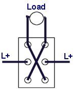
The diagram you sent to me is correct. Note that the wires crossing in the center of the switch are not connected to each other at that point.
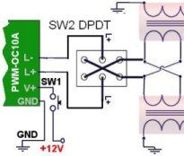
Also if you want to use as open collector, just replace the connection to L+ with the connection to your other source as shown previously.
Thank you,
Okay now I am confused…I-I mean my blond is showing: )
Could you please detail the polar reversing switch in schematic from, as it would be connected from the PWM to the twin anti-parallel coils differentiating between positive and negative power source e.g. battery and those of the inductor connections on the PWM?
If I can get this right my plan is to use the polar reversing to achieve ascend/descend maneuvers on the EGV-3 while using the PWM as the electronic throttle! The main goal being to achieve a sustained hover-mode and up/down maneuvers so I might need to reverse polarity assuming one polarity could be either up or down…
Make sense?
Rob
Yes. Use a DPDT (double pole, double throw) switch and wire as shown in this diagram. I would not recommend switching polarity when running at high power as there could be arcing inside the switch.
Thank you, how about a polar reversing switch i.e. can this circuit be wired to incorporate polar reversing?
Do you have a diagram for incorporating a polar reversing switch?
Rob
Yes, Instead of connecting to L+ on the PWM, connect that wire to the +ve of your other power source, and make a common ground between that and the 12V source for the PWM. The source must be tolerant of voltage spikes.
Considering that your Plasma Gun’s twin coils are connected anti-parallel is it possible to wire the power supply using the open collector mode on the PWM?
Do you have a schematic diagram for this type of wiring scenario?
Rob
I was wondering when someone would get around to thinking about keeping the plasma alive using microwaves, as this is exactly what I am doing with my EGV-3 gravitic technology using asymmetric cavity structures and/or over-mode capacitors to contain the plasma!
Robert A. Patterson
http://quantumgravitics.tripod.com
Yes, exactly.
Ok, so if taking away it’s energy source kills it, could you possibly keep it energized by bombarding the plasma with microwaves, or some other type of radiation?
Rick,
No. The RF ground should be a totally independant ground.
Blake,
Plasma can be held by magnetic fields, but if you take it away from its energy source, the plasma would loose its energy and just become normal air again.
Is it possible to trap the discharged plasma inside a magnetic field, or will it just dissipate? Is there any way to store the plasma for a short period, to possibly concentrate it?
just a quick silly question does the rf ground be connected to the ground wire of the power pulse modulator thanx
That just looks like a drill 2 me, but i am only 12!!!
Rob,
Yes I meant battery -ve as ground. Look forward to seeing it.
Fury,
A very high power UV laser would be used to create a path of ionized air.
Hay, just wondering if it would be posable to use a laser (Ihave no idea of type, power or frequency) to create an ionized pathway for the enagey to travel? (like the new stunguns being developed) possabley combine it with a jet of argon? feasible?
Thanks; I was hoping to use a non-grounded reference e.g. use the negative battery terminal as the only grounding plane.
My circuit won’t be used in the exact same manner as your Plasma Gun. The top load components in my circuit are going to absorb all of the RF output, or so I hope: )
Ill upload a photo or u-tube video as soon I get the circuit operational.
Prepare to be surprised : )
Rob
Well if your coils are connected in normal parallel arrangement, their outputs will be in phase and the HV will be between the outputs and GND.
RMC
It’s just the two leads +/- from the battery connected to the twin output coil.
Alex
To the contrary no question is stupid, i.e. if the person doesn’t know the answer it means they are looking for guidance and not asking to be ridiculed.
Rob
Just happened back along here. I have a message for all you novices…
Please, look up what a tesla coil is and how its circuitry works before asking questions.
I learned that the hard way here. But now, I have my own coil and it works spectacularly.
So seriously, guys. Get a little info before you ask stupid questions. Wikipedia is excellent for this sort of thing.
IF you read up on how tesla coils worked you would not find the diagrams that confusing. After all, this is not a tutorial site where the author basically assumes everyone who reads it knows nothing about what the subject matter is and explains every small step in great detail. This is a site for people who are educated enough in the basics of what they are trying to do that they don’t need those kind of things.
If you read up on these coils, you would know that of course a welding transformer won’t work. It ups the current to get the super high heat needed for welding. A tesla coil transformer needs to do the exact opposite: it ups the voltage.
So please, people. Do a little research instead of bugging these people with obviously uninformed questions.
If you do eventually need to talk to them about a legitimate problem afterwards, hopefully by then you will be competent enough not to embarrass yourself and waste their time by asking a question with an extremely obvious answer.
I’ve never used such a coil, but I would excpect that the twin outputs work in phase. I’m not sure of the arrangement you describe, how many input connections are there?
What would be the result of using a motorcycle coil with twin high voltage outputs but not connecting the coils anti-parallel?
Would this arrangement still charge the tank circuit?
Rob
Chokes are non polarized components so you can connect it either way around
Mr. Robert
For currency, plz, use Google 😐
Just type “£ to $” to search input. So ez ^^
Btw, DIY staff. Does it matter how I connect my choke? Color code on that is silver-black-black-brown.
Thanks!
Obviously I am aware of doubling the amount of cost and the dangers of building Tesla coils.
Are you aware that kits and working Tesla coils are sold on Ebay?
Just write a use at your own risk clause.
I have to agree with several of the post above this is one of the best sites, many others wont even give you the time of day : (
Thanks again for breaking it down for us novices!
Rob
Actually C1 can be larger, really the bigger the better as it is used as a smoothing capacitor. There are laso 1nF capacitors in the shop, they are marked as 1000pF.
The 20kV or 30kV diodes would be fine. With the diodes, it is best to go with higher ratings as it means they are less likley to be damaged by any accidental over voltage or current.
I will update the parts list to make it easier to find things later today.
I can’t really offer a kit becasue it is a potentially dangerous device and would need all sorts of saftey testing. Also some of the parts, such as the primary and secondary are hand made using random surplus parts.
The exchange rate varies dailly so I can’t put prices in USD. You can easilly approximate as it is typically twice the number shown in GBP. (£1 = $2)
This is just a suggestion but it would be nice if you would post all the parts for this project on this same page there above where the messages begin.
You could post a completed unit for an assembled price and then list a kit for the DIY’ers to assemble and then list all the components individually for those of us that want to buy just a few individual parts for a our own projects, but on this page where this project is located. Doing so would make it a lot easer for all parties concerned.
I know I would buy a kit with everything except the drill gun for my project if all the parts were located on this page that way I don’t have to hunt and do conversions to figure out which parts I need because they would all be for sale with photos of the part and shopping cart all on this one page.
Just one more thing, it would be nice to see the cost for the items in USD currency too : ) As this would encourage me to order more with more confidence knowing exactly how much each item is without me having to do conversions.
Thank you,
Rob
Okay, that helps some with selecting C2 15kV 2200pfF from your site but what about C1, which is only 1nF according to your schematic?
I guess I would have to connect several caps together in order to reduce C1 down to 1nF?
What about the diodes, your schematic calls for 4 x 15kV at what mA? Your site list 8, 10, 20 and 30kV diodes but not one 15kV diode so how do I know which parts to order from your site?
Sorry to be such a pain I just want to order the right parts the first time form your website, that way I support your efforts : )
Rob
1000pF is equal to 1nF. The unit of capacitance is Farads (F) the letters prior to that just indicate orders of magnitude. It is just like how one kg is 1000 grammes
You know this gets real confusing to us novices when your schematic calls for one and two nF caps but then you link to capacitors labeled in pF, so what gives?
I would like to build something similar to this so it sure would be nice if you linked to all the parts for this project on one page…
Rob
Tyler,
Erm.. See above.
I.Q.,
The sparks will be roughly proportioanl to the input current. Doubling the input voltage would probably double the current, but the components used would overheat. A physically larger device would need to be built.
OAK,
Insualtion wont protect you from a Tesla coil or lightning. A metal suit connected to ground would. No ball lightning.
CAN THE TESLAGUN CREATE BALL LIGHTNING?
Type your message here
HOW MUCH IS THE INSULATION CAPACITY OF THE TESLA TROOPER ? OR WOULD A TESLA TROOPER SURVIVE AN LIGHTNING BOLT STRIKE ?
Changing the battery would make the sparks larger bt wat would be an adequate increase to make the sparks substatially larger
This project looks amazing and I would love to do it. Is it possible to have a list of all the necessary materials and how to put them together.
Yep
Ye, I thought so too and thx for giving tips.
I presume that rectifier’s connection is contacted to long neck’s end?
You can snap off the long neck of these to make it shorter, you will just need to insulate the end conection well to prevent arcing.
Some of those are inernally potted in resin which is difficult to remove.In this case you can just leave out the secondary coils connection to gnd. When like this, don’t try to run the coils without them connected to a load or the back emf might be too large.
Here’s a photo for you:
https://www.rmcybernetics.com/shop/high-voltage/hv-spark-coil
I don’t really understand which parts you refer to. Can you send a photo labelling them?
Myes, I’ve opened one and was wandering are the output-head and black input-head removable.
And another “nubish” question is which of the coils is connected to anti-parallel to PWM? Outer or inner?
Guggis,
Depends on your cou\il, they are all different. Usualy a stanley knfe and crewdriver wold help.
OAK,
No, the welding transformer would be useless.
Uhmmm, how I’m supposed to open the casing? 😀
Too difficult for my skills xD
Type your message here
WOULD A TESLA COIL WORK IF IT WAS CHARGED WITH AN WELDING TRANSFORMER OF 500 AMPERE IN ADDITION TO THE ORIGINAL POWERSUPPLY.
IF IT WOULD WORK WHAT WOULD THE RANGE BE
Moar fancy questions: How ignition coil is removed from it’s casing? Packing mechanism is too high for my skills.
Actually, it a plastic pipe with a single long piece of thing enamel coated copper wire wrapped around it to form a coil.
What did you use for the primary? That looks like copper tubing used for plumbing.
Hmm, okkay. Thanks for info o/
It comes fitted with a 40mm fan. With the fitted fan and heat sink, it will power this device fine as long as the trigger is not held for too long. A few moments are needed to let it cool.
A larger heat sink would be more effective than a larger fan.
Is the fan of the drive circuit how huge?
Yes, but the transistor of the PWM-OC10A may need more cooling.
What about 18V? Does it work properly with 12V’s components?
Already designed a 1.2-1.6 million volt tesla gun on computer though it is going to cost about $1500 to $3000 dollars Australian to build even the suit will be fully funcional for routing the RF ground to the ground and there will be a status panel on the right arm to monitor the battery conition the output of the inverter and the inverter and battery operating tempreture.
And all i can say also it will no more weigh than 6 kilograms due to titanium construction of the tesla gun.
Any chance that this Plasma gun could be used to generate an oxygen plasma for etching or cleaning surfaces (a la semi-conductor industry application)?
The damage will start happening between the layers so you may not see it at first or until the power is high enough.
The wire used was about 0.2mm thick.
Ouch. Wierd, though. I’ve been doing that and my coil hasn’t self-destructed yet. I guess I’m just dang lucky. But if you didn’t do that then how did you get your primary so short while still doing 520 coils? Did you just use very thin wire? If so, how thick is the wire you used?
No, Your coil would self destruct if you tried this. The voltage difference generated between each turn of wire is quite significant. If you double back, you will have very high voltages between the layers and your insulation would not be sufficient. It would be likely to burn out. Even if the insulation was perfect and indestructible, the capacative coupling between the layers would prevent efficient operation.
Also, when winding the secondary coil, is it OK to double back when you reach the end and keep wrapping back and forth over the previous wraps?
If you have the patience, make it an SSTC.
Be raedy to spend some time tuning and tweaking it for performance.
Smaller coils are even harder to get to work.
hello, I’m an aspiring coiler and I’m trying to design a small hand held Tesla coil that runs off of a 12v power supply, I just wanted to know if their are any tips you could give. (I’m trying to make it no larger than 7″ long and I want it to be probe like).
The knobs on the PWM-OC10A should be adjusted to give the most rapid spark gap firing rate you can get.
As your coil is of a different design, you will need to ‘tune’ your tesla coil. If you used insulated wire on the primary coil as we did, I would think the best way to tune it to try different capacitor values for C2 or try varying the number of turns of wire in the primary coil.
The specific number of turns used is not as important as getting the primary and secondary circuits to resonate at the same frequency. I think that 31cm would be too long if it is as narrow as this one. Even the one we made was probably too long and narrow for optimum performance.
C2 and L3 form a parallel resonant circuit which will oscillate at its fundamental frequency which should be made to match the resonant frequency for the secondary circuit C4 and L4. In addition to the capacitance of C4 the coil its self will have a ‘self capacitance’ which can be harder to calculate. This oftem makes it neccesary to manually tune the coil as described. Here you can find some info about Tesla Coil Calcualtions
One more thing, our secondary coil contains about 520 coils, but it ended up being 31cm in length. Yours appears about half that. What did you do to make it so short? Did you double or triple up on the windings? Would this cause the output drop I am experiencing?
Also, if we turn up the knobs to about halfway on the primary circuit, we notice a very small spark, if that helps.
Ok, we have assembled the tesla coil. We have a problem, however. The spark gap is firing, but nothing is coming out of the topload. Any suggestions to what might be wrong?
The secondary coil is grounded…
Also, what should the knobs on the primary circuit be set to?
The TC secondary is connected to RF ground which is separate to the power ground. If you used the power ground the RF energy would interfere with and possibly damage the driver circuit.
Then I have a question: Why is the secondary coil grounded to a copper plate on the grip? Wouldnt it be easier and safer to ground it to the battery?
The ground of your coils depends on the type. It is normally connected internally to the primary coil. If you cant open it to seperate it, you can just leave it out.
The ground is on your power supply or the negative terminal of your battery.
Two things: where are the grounds on the spark coils and what are they grounded to?
Nothing is new under the sun… I used a model t ignition transfoemer (they were self exited with a vibrating interrupter) a spark gap and resonating capacitor made of plate glass and aluminum foil with a copper tube primary and a secondary wound on varnished paper carpet tube and that was in 1955… In 1960 I made a 7 ft tesla coil with a neon sign transformer and a pair of 811A’s (large transmitting tubes) driving a copper tube primary with an 8foot secondary (also paper carpet tube) Blanked out radio reception for 10 miles around… didn’t need transistors OR plastic
Carefully with a stanley knife and a hacksaw.
How are the cases of the ignition coils removed?
RF Chokes are simply coils of wire or inductors. They are used to allow DC to to pass through them for charging the capacitor whilst they block the high frequency from the primary coil+capacitor from getting back to the diodes.
If you dont use the chokes, when the spark gap fires, it can cause current or voltage spkes which would damage the diodes.
The coils are constantly loaded in this circuit and will never get as high as 20kV, infact the spark gap was set to fire at around 5kV but your components must always be rated significantly higher.
There is no direct relationship between the number of turns in this type of transformer. It depends on many factors.
I apologize for all the questions I have been asking, but my father has these questions about this project that I really don’t think can be answered by anyone but the person who made this device.
First of all, why are RF chokes necessary, and what problems are caused with the device if RF chokes are not used?
Also, It says the spark coils generate about 20kv of energy. Why do you only need diodes and capacitors that can tolerate 15kv?
Lastly, with the primary coil having 5 turns and the secondary having 520 turns, with a direct relationship between the increase in number of coils to increase in voltage, wouldn’t that mean that the 20kv put into them by the spark coils would increase 100-fold to about 2000kv?
Ok, cool. Thanks again.
They are only available here. We will have stock available again next week.
I have read up on tesla coils, and feel I really understand how they work now. My only remaining question is this: where else can I find a “Power Pulse Modulator” that will work for this project? The one sold here has been back-ordered 14 times, and I was wondering if you knew of anywhere else where they sell this item. The only ones I have been able to find don’t match the specs of the one sold here.
Thanks, Alex
I understand. Thanks for your time. I really appreciate it.
You must learn more about a Tesla coil and how a Tesla Coil works or you will not be able to make this project work.
Yes the secondary wire is enamel coated copper wire aka magnet wire.
You have a lot to learn before you should try a project like this or it will just not work. I can’t possibly explain every detail.
are the secondary wires coated with anything?
Huh… It appears the primary coil is attached to some part of the circuit in the pictures, but it doesn’t say anything about that in the diagrams. even with that, how is the primary coil attached to the machine, and do the primary and secondary coils touch?
Yes plastic. You are seeing things. It has to be a coil or it would not work. It is a coil of fine wire wrapped on a plastic tube. All attached together with epoxy resin. You are going to have to use your imagination to find the parts.
Also, how are the primary and secondary coils attached to the machine. I can’t really tell from the pictures. And one more thing, can any of these parts be salvaged from appliances you might find around the house? If so, which parts, and what could you find them in?
Plastic? And it appears in the pictures that the secondary is not even a coil at all. Am I right, or am I just seeing things?
Just some random plastic parts from old toys or anything. Just use whatever you have available.
What are the primary and secondary coils made out of?
Frank,
The output from the ignition coils does need to be rectified.
FB,
1.4nF is quite small and will therefore create a higher frequency resonance than a larger capacitor would. You may be able to compensate with more turns on your primary coil.
It is all about matching the resonant frequencies of the parts so you have to make your coils match the capacitor used.
Alex,
A drawer handle from a DIY store.
Where’d you get such a small top load sphere? The smallest ones I can find are 3″ in diameter
I am building a Tesla Coil, and want to know if a capacitance of 0.0014 uF @ 90KV would be enough to give good results. The coil is driven by 2 Ignition coils (12V SLA powered), and has a secondary height of about 70 cm.
Thanks for your help.
Thanks. 1 more question, do you need to rectify the output?
The charging current for the capacitor here is low and via some diodes. This just helps with preventing HV spikes getting back to the circuit. When charging from an AC transformer like an NST, it is not so important.
I have seen other Tesla Coil circuits where the spark gap and the capacitor are in opposite positions to your setup. Why have you done this?
Man i built one out of capacitors, couplings, copper wire,etc. but the box was a fire work box…I was wondering if you would post a version of Mr. Tesla’s hand held oscillator…that would be cool thanks for pictures and all. Continue to light the world.
Dangers are from fire, electric shock (causing you to possibly injure yourself indirectly), and interference with nearby electronic equipment.
Coils from an autospares supplier, maybe you can find other parts in a local electonics shop.
Drill just has a convinient shape, battery and switch.
Hi!
My friends and I are making this for a high school chem. project and we would like to know a couple of things.
1) What are possible dangers? Are measures of safety did you take when you made this?
2) Do you know where we can get the parts other than your site (we need it soon but your shipping date is past the due date). What stores do you recommend?
3) Why a drill? Are there any parts in the drill (aside from the battery) that is critical?
Thanks!
The UV light would have to be very intense to be able to do this effectively. The UV light its self would be quite dangerous.
Couldn’t you use an UV (or is it IR) diode to direct the arc instead of the noble gas?
If by voltage you mean the input voltage, and if my vary you mean increase, the result would be a proportionally increased output power and faster firing rate.
Type your message here
if i vary the voltage upto 2 times,what will be the result
Хуясе о_о
It is not steady if you just have diodes. You would add a big capacitor after to smooth it out (This is what C1 is for in the diagram). I posted a diagram about this somewhere for somone, but I really can’t remeber where unfortunatley. If you find it let me know the page and msg number.
when AC voltage is full-wave rectified, does that mean that there is a steady DC voltage coming out? or is it pulsed?
thank you!
The only parts we have on sale for this projects are linked in the parts list here. The coils of the Tesla Coil can easily be made by winding enameled (insulated) copper wire around a plastic tube. The actual dimensions of the coil (L4) can be different to that shown but this would mean that some other adjustments (C2 and/or L3) would need to be made to make it match. There are many variations that could be made to this project. Changing some of the parameters and observing the outcome can be a good way to learn.
My son is in second year electrical eng. and wants to do a second major in physics
I am looking for Christmas ideas and wondered if I could but everything needed for this project as a kit…except the drill of course. I know nothing about this stuff and think I could easily spend a hour on this site just trying to find all the parts. It would be great if a package deal were available with basic instructions or the like. Thanks
No more significant heat or light is produced by using Argon in this system. The output current used here is very very low so the plasma temperature stays relativley cool compared to a TIG. The heat/light produced will be proportional to the current flowing in the arc. This uses something less than 1mA (0.001 A) where a TIG will use around 200A.
I noticed you mentioned that argon gas was being used to create the arc in one of your pictures. Does this generate much heat, or UV light, it just seems very similar to the plasma weld TIG effect. (if it does produce any UV light you may want to avoid looking at it, as it can cause “arc eye”)
Great build btw.
I doubt that very much indeed. The transistor was not invented until 1947. This device contains a power MOSFET, 2 IC’s containing hundreds of transistors and rectifier diodes. The HV capacitors (condensers)here would have been impossible to make back then and an equivalent would be much larger. Even the battery stores much more energy per unit mass than would have been possible. The noble gas would have been very hard to get in 1938. Oh yes, it is also cased in this mystical substance called plastic!
So what’s new??
I did the same thing with an old Model-T Ford ignition coil in 1937/38!
A very interesting device, I have thought about making one myself.
I think your idea based on the classic tesla coil is good, and the working unit is excelent.
If i was to make one id try to go solid state all the way, it may give you better power efficency over the traditional spark gap method.
I would also be very tempted to construct an aditional coil and make the system like a magnifier, this will help lower the res frequency down to more manageable levels, as well as giving you more of a voltage feild.
if the frequency is low enough, you may even be able to use ferrite powder, or bits of ferrite in the center of the sec tube, to improve coupling.
Anyway I look forward to seeing more of your work
THE DEVICE IS SIMILAR TO RED ALERT2 TESLA TECHNOLOGY
WHAT IS THE RANGE OF IT
Ah, memories of my high school physics class. Mr. Flanagan left an insulation tester gizmo running on his lab table and left the room momentarily with the warning “this thing’s hot, so don’t anybody touch it”. Of course, the class machos all checked it out. It resembled a soldering iron to the extent that it was line powered and had a bluntly tipped metal probe, but the handle was big enough for two people to hold with both hands. It could throw a spark about 2 inches and if you were the sparkee you wouldn’t be inclined to try it again. It was our physics teacher’s most memorable practical joke.
i like this its given me a great idea.
get a massive can sized capacitor full of tonnes of electric like with the can crushers, and use that instead of batteries so instead of a steady thing like that you could do what the posted vid does but have to reload each shot.
It is a low voltage square wave pulse generator with protection against HV spikes.
whats the pmw oscillator my family thanks you for any advice 1000 thankyous
An ordinary light bulb and small florescent tube were used.
cool! what kind of lite is that?
I’m planning on building a small, low Hz tesla coil, like the other guy with the handheld one. (exept not handheld) What kind of things should I use?
It would tingle quite a bit. The arc jumping to a finger would possibly cause burns if left for several seconds. The RF electricity traveling through the body is probably not good for you either.
How hazardous is the output of this TC? What would happen if one touched the globe while it was running?
Thanks for your help.
Adam,
Yes, the plasma will just reach for grounded objects like an ordinary Tesla Coil.
bd,
Ever heard of a glue gun or a staple gun? They are used to create things, not destroy them.
What’s the point of making it shaped like a gun if all you can do is light up light bulbs with it? A gun should destroy stuff!!!!
Is it possible to make this and still have it work without having a gas supply?
Yes.
About the HV diode, is 2CL77(20kv 10ma) ok?
what would this do to the sensors in stores by the doors?
would it make them go off?
if so, that is a fun little toy.
Just found this video of an amazing hand held tesla coil. It needs to be plugged in to the mains but it’s certainly impressive. Well done JM Labs and teslacoil.net
By putting a UV laser in there you might be able to generate a sustained path of ionised gas between the unit and the target. just have it fire out the hole in the topload sphere.
Set Phasers to tickle!!
To make this effective, you need to apply one of those systems that rarify a column of air from the tip of the device.
Drill a hole through the ball at the top of the coil. Devise a CO2 laser of suitable wattage and compact enough to fit inside the coil’s cylinder.
Richard did you talk my wife into buying me an 18 Volt cordless drill for my Birthday. I never asked for a drill and now you come up with this idea. I guess the drill will have to break sometime.
Can i break it now!! ..
Just be careful… telsa coils actually produce
radiation… I wouldnt
want to be exposed to that.Just look at the way Tesa and most of his
associates died…Being blasted with x-rays just because it looks
cool can really be a bad decision.
http://en.wikipedia.org/wiki/Tesla_coil
So if I had a huge, permanent one thats alot more powerful in my room, and left it on 24-7 it could be bad for me?
Nothing that would be immediately noticeable, but excessive exposure to any source of RF would probably not be good for you. Although the mobile phone companies would probably disagree.
Does this cause any harmful effects to people?
Higher power, and it runs from batteries. This ciruit uses transistors and compact coils to ‘invert’ the DC into HV AC for charging the tank capacitor. It also hase the gas jet feature.
How is this circuit different from a ’20’s vintage Violet Ray wand?
The gas line is not necessary. It is just an added extra for directing the plasma out in a straight line. Without gas flow, the streamers will just look like those from a normal Tesla coil.
Rough costings as follows;
Cordless Drill – £10
Drive Circuit – £40
2x Spark Coils – £30
4x Diodes – £8
3x Capacitors – £5
RF Chokes – £1
Topload Sphere – £3
Coils & Former – £5
Spark Gap – £3
Time to Build – Priceless
TOTAL £105
That’s buying everything new, you could probably lower the cost by using salvaged parts.
Hi there. You all have some great projects — great ingenuity! I have 2 questions:
(1) Is the gas line neccessary, or only for the purpose of emitting streamers from the end of the “gun” itself?
(2) What would you estimate the total cost of the project to be?
Thanks, and good job!
“The body of the person holding the device is used as the RF ground and the large area of copper ensures the energy is spread out to prevent RF burns.”
Possible to use an RF antenna ‘dummy load’ here instead? (Just in case somone wanted to up the power)
Hey there keef, glad you like it. The bottom picture is supposed to show Argon being fired from the end. Unfortunately my digital camera is pretty rubbish for this sort of thing. I’ll get some better ones with my SLR at some point.
It works well using Neon too, bright red. If it’s forced out through a tiny opening it will make a long straight needle like plasma jet.
Dude, This is pure class. Good to see your making it on hackaday website.
Should make it so you can fire ionised gas out of it so the sparks can go better.
how did you learn of this, damn, your good, real good
lol. None taken. I think that just says a little something about how your mind works!
No offense but… This looks like a sex toy of some sort. Like its supposed to make a super erotic sensation.
High voltage diodes and capacitors can be scrounged from an old TV set or computer monitor. Large color sets put out 25 KV or so. And the power supplies can be used for other projects too..Just BE CAREFUL cuz that kind of stored energy can kill you!
RS seem to be discontinuing the HV diodes they used to sell. You can buy High Voltage Diodes from our surplus store.
The tank cap is just two identical caps in parallel.
I would like to know two things about your new project.
1) Where does one obtain the HV diodes rated at 15kV…do you know if RS components do these or is there an alternative source from old equipment?
2)Is the final tank capacitor a single capacitor or an MMC? I assume it’s the former.
The drill is not important. It just serves as a box, a switch and a battery.
hey man what if i cant get a drill machine