A Homemade Voltage Multiplier (HV DC PSU)
 Using a voltage multiplier is a great way to make a high voltage DC power supply. It is very easy to generate high voltages from easily available components.
This page contains information on where to buy the components and how to connect them. It also gives details of sources of mini high voltage power supplys (inverters) which will run from batteries.
![]() WARNING: Very High Voltage Device!
WARNING: Very High Voltage Device!
 You can see what high voltage static electricity from this device does to a piece of one way window film in the violent discharge experiments section. There are microscope images of the aftermath and a video clip of the explosive action!
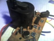
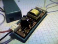
For efficiency a voltage multiplier should be powered from a source that is already a relatively high voltage. There are a variety of small battery operated high voltage power supplys available. Many lighting devices contain inverters for powering vacuum tubes such as, florescent lights, cold cathode lights and plasma globes. These types of devices usually run from 12V DC and can output voltages up to around 20kV AC.
|
Mini cold cathode tube PSU – ~1kV |
Plasma Globe PSU – ~15kV |
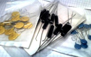 The capacitors and diodes required for the multiplier can be purchased from our shop.
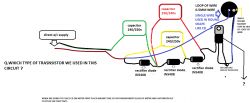
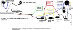
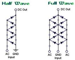
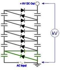
The capacitors and diodes can be arranged in a variety of ways. The half wave method is the easiest as it requires fewer components, but a full wave circuit will perform better. If you just want to get one working as soon as possible the the half wave method would be adequate. The circuit diagrams below indicate how the components should be arranged.
|
Component
|
Max Voltage
|
Source
|
|
1 – 30kV
|
||
|
1 – 30kV
|
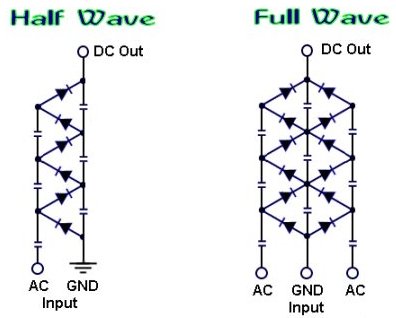
 The schematics above will output a positive DC voltage relative to the ground (GND). If a negative output is required then the polarity of the diodes should be reversed. you can learn more about how a voltage multiplier works, by visiting the voltage multiplier page.
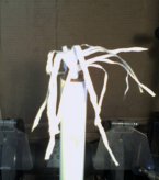
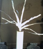
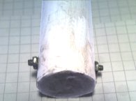
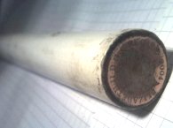
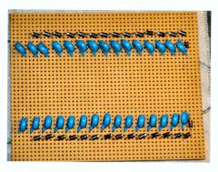
For safety and improved performance the voltage multiplier should be placed in a protective casing, such as a PVC pipe filled with oil. The image on the left shows two protruding screws used for the AC input connection, and he other image shows polished coin used for the high voltage output. By using Polymorph to seal the ends of the pipe, it can be filled with oil to prevent corona leakage from the internal connections. A more sturdy method would be to fill the pipe with epoxy resin, but this may be difficult with compact component arrangement.
 Example Experiments
A homemade voltage multiplier is perfect for powering an EHD thruster (aka Lifter). An EHDT can be made from just aluminium foil, sticks, and fine wire. To learn how , see the ElectroHydroDynamic Thruster page.
Using freezer spray (used by plumbers) you can grow ice crystals on the HV output with interesting results.
For more Simple Experiments with static electricity see the Experiments Section


Hi, Would a full wave voltage multiplier work for a high voltage circuit in bug zapper or is there a better design? I would need to go from 120v to 8 or 10k.
Hi, can any one still add comment?
I am trying to multiply 24VAC input up to 2400VDC with 100 stage.
My questions are:
1, is full wave circuit giving twice as high voltage(2400VDC) as half wave circuit(1200VDC)?
2, Does any component or the AC input itself decides the output power?
3, I am trying to charging a 2400V capacitor with huge capacitor. If I connect it the output directly, would the current goes too high during the charging?
Many appreciates if anyone can help me!
Hi sir, my AC input is from 2 car battery in series and 555 circuit. RMS value is 17V. My questions are:
1. Is it possible to build a 20 stage multiplier with this input to 3400Vdc output?
2. What power range can this circuit handle? Because to me it seems that when this high voltage output connect to any load with low resistance the current would be high.
3. In my experiment the load gonna be a simple huge capacitor. Would this work?
Thank you!
Yuhan, the impedance of the capacitors will vary with frequency and will therefore cause changes in output. 10V is probably too low for a starting voltage as the voltage drop in the diodes will be significant. Check the Vdrop rating of your diode, it could be pretty close to 10V.
Hi, Help with a voltage multiplier please:
Input voltage range 10-60v AC
Output voltage 100-600v DC
or basically a 10x multiply on ac and a Full wave bridge rectifier..
thanks, Bill
Hi sir,
I am trying building a 6 stage voltage multiplier and I started to test with low AC input(10V peak to peak) from function generator. The thing is if I use DMM to measure input, it will decrease as the frequency increases and the output increases as the frequency increases. And only at a certain frequency, I will get the desired output I want but the input is not what I have in function generator.
My questions are:
1. Is it the input suppose to be change or not?
2. Do I need boost the input AC value using transformer for testing. Is it because the input I used is too low?
3. How do I adjust the input frequency? How does frequency effect the whole circuits?
BTW, I use a cap rated at 6kV and 1nF. Diode rated at 4kV.
Thanks
Mainly due to losses. There are losses in each diode and also there are losses to the surrounding through ionisation. The physical size for a multiplier might also be inpracical compared to a suitable HV transformer.
why no. of stages limited in voltage multiplier circuit? acording to voltage doubler principle, if the stages are increased to max no (say 50,100,150 etc) then voltage voltage multiplied up to infinity But it is not possible. WHY? thankyou for helping us.
Yes volt drop makes it inpractical to use a voltage multiplier. Google Joule Thief. That is exactly what you need.
Hi.
I have a 0.5 Vac voltage source @ 70 mA. I want to use this source to power a LED at 3V @ 15 mA to illuminate something. My question is: Is it possible to do this by voltage multiplier ? In theory, i think it will be necessary 5-6 stages of diodes and conds, but my concern is drop voltage of diodes. Or is it another way to make this ?
Thank you.
hi sir one of my friend recently add one transistor first pin when we put no.side up to anode diode and capacitor both and second pin to the loop of wire,and third pin remains unconnected he still got this project with him.I am not sure it may be in between BJT or alternistor.thanks any way
You can not use a transistor on the HV output as the voltage is just too high.
hi sir,i only want to know which transistor(name and identity no.) we can use when AC flows in voltage tripler and which transistor is placed at output which produce noise
parts – 3 capacitors 400v, 3 rectifier diode 1N5408, AC SUPPLY 240V and no circuit board is used.
thank very much.
hi,I want to know when AC flows through 3 capacitors 400v and 3 rectifier diode 1N5408 in voltage tripler circuit so if we add 1 transistor which only first 2 pins attach at both the ends and a loop of wire and small magnet kept over the wire loop looks like cd ,it produces sound like tic-tic very quick what type of transistor and its identity no. to perform this action.thanks in advance very thanks.
Larger capaictors mean a lower impedance and therefore allow a higher current flow.
Dear Sir,
What problem happens if we use oversize capacitors for making a full wave multiplier?
I want twice capacitors in order to reduce full load and no load voltage drop.
Thanks.
Full wave can be more efficient. I can not help you with the specific component requirements.
Dear Sir,
I want to make a full wave multiplier by doubling voltage of a 7500V boiler ignition transformer to reach a 15000V DC voltage for scientific purpose.
Should I use a center tapped ignition transformer for a full wave output?
May you guide me about suitable capacitor and required diodes for continuous operation (7/24) at 2mA passing current?
Many Thanks.
Make a Voltage Divider using a string of ten 10M Resistors and one 10k Resistor. Measure across the 10k resistor to get a reading that is about 10,001 times lower than the real voltage.
Thnak you so much for the reply.. could you please send me a link or post a page on how to make a voltage divider to check 8kV in a standard multimeter?
A capacitor does not store any charge. It stores energy. You will not be able to store the energy from the chassis of a plane unless you can get the static to continuously flow as current. When in the air you will have no earth connection so this would require some device outside the aircraft so that it can be discharge into the air via some ion stream or corona discharge. If you can do this, then the energy could be stored in a bank of high voltage capacitors. You would then need some sort of SMPS or buck converter to allow you to charge a battery. If you need more help with this project you can contact us to hire a consultant, but I can not offer help here as it is not relevant to the topic.
Hi,
I am a student doing my Bsc in aviation and we have a project in which we want to harness STATIC ELECTRICITY .. i.e we want to put to use the static electricity produced on the aircraft instead of just discharging it in the air..
So are approach was to start of by building a static generator(which will represent the static electricity on the aircraft during flight)
..after researching we finally built a voltage multiplier (half wave) circuit which fulfilled our first milestone.. and then we came across your page and we think you could help us out..
For the second part we now need to store the high voltage that is produced through the multiplier circuit..so could you tell me a suitable type of capacitor rating to store this 7.4kV ??
After storing this charge we want to put this to use .i.e. we want to show an application by,say..charge a battery maybe around 24VDC.
For that we need to step down the 7.4kV (from the voltage multiplier circuit) at the output to around 230VAC , after which.. We would use a transformer and further step down and rectify the voltage to use it to charge the battery..could you please help us with this?
kunal, this page is about how to make a high voltage multiplier.
sir i want to amplify and covert an AC signal having properties like 1.5V and 150nA at 20Hz frequency in form triangular shape wave into almost 4V DC supply. Then what type of multiplier i have to use or if i want to make a multiplier by combination of capacitor or diode then what type of diode and capacitor i have to use.
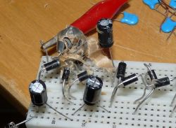
Better picture for viewing
You may have right. I did some errors too : on the previous picture, you can see that the second diode is put in the wrong direction ! The first diode also was not connected to the bottom capacitor ! shame.
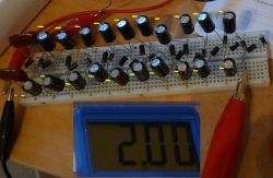
Anyway I re-tested with a good circuit, and the electrolytic caps in the first stage didn’t explode, but get significantly warm. To avoid this, I put 2 cbb21 Metallized Polypropylene Film Capacitor for the first stage, then the rest of stage are 1uf (or 4uf) 400 V electrolytic (see the side picture which show also polarity). It work really well, at the 23st stage I get 5.54kV. (don’t have more caps to continue) : Picture show the 11st stage at 2kV. Hv probe are very useful.
With full CBB21 400V 224J, I have an HV wall (can’t get more voltage even if I add more stage). It appears at the 18st stage at 4.4kV. The 23st stage stay at the same voltage, circuit seems saturated.
Same remark for :
_Ceramic Capacitor 2KV 0.001uF, HV wall begin at the 3st stage ! hv max : 730V (I put always 220V input)
_DIP Mylar Polyester Film Capacitors 1000V 0.001uF, HV wall at the 3st stage, HV max : 640V
Observation of HV wall was unexpected for me because no one speaks about them on internet. These guys observed it with different capacitors :

http://www.ajol.info/index.php/bajopas/article/viewFile/63808/51627
I get the same result as them, their article illuminated my whole comprehension of CW circuit.
So the best caps to use with CW generator is :
Electrolytic, then CBB21. Ceramic don’t work for me. Thanks RmCybernetics to share you knowledge with us. Regards, JS France.
Polarity. Electrolyitic caps are for use with DC only. They will explode if you apply the wrong polarity to them.
Hello =)
My 1uF electrolytic capacitor just exploded on my face when I put the 220V input. It smoked then exploded in all pieces.
I don’t know why, because it’s rated at 400V.
I put an other capacitor in the first stage, and the rest the same electrolytic caps, and it seems to work. If you have an idea.. =)
Please read the other comments. This has been answered already.
i am constructing voltage multiplier 12 stage. capacitor 150 pf 15 kv and diode 20 kv.output current i required is 150 micro amp , what should be diode specification
Hello,
I am working on a project that requires roughly 400 volts DC. I recently built a voltage multiplier using a half wave design. I am using 1.5nF 3kV capacitors and 1N4007 diodes. My input it 120 AC. When I measure the voltage after each stage it starts a 134 DC then drops to 105 DC and holds that through the rest of the stages. Any help/ideas on what the problem is would be greatly appreciated.
Thank You
It says in the article…
“The schematics above will output a positive DC voltage relative to the ground (GND). If a negative output is required then the polarity of the diodes should be reversed. you can learn more about how a voltage multiplier works, by visiting the voltage multiplier page.”
I would like to build a negative ion generator. It looks to me like the Voltage Multiplier produces a positive voltage as its output. How can that be used to generate negative ions? Note that it produces a positive voltage wrt to ground. This ground is an earth ground. So if i use the other lead it will just ground out whatever I attach it to. I noticed that several people have asked related questions and there has been no clear answer.
I think there must be something fundamentally wrong with your measurement technique. Also your choice of components is not good.
Another thing I notice is that you are using small 2kV capacitors and two 1kV diodes in series. The small capacitors will be inefficient, and the 2 diodes will just cause excess voltage drop.
You don’t say what the output of your inverter is, but assuming it is about 80V (from your C1 measurement), then there is no need to have diodes and capacitors rated to withstand 2000V.
Dear Sir,
I made a voltage multiplier from an ionizer circuit for car(that circuit got DC input around 2 to 7 VDC, got DC – AC converter and transfomer to amplify the voltage )
Initialy it has 4 stages ( 8 capacitors) and I added 4 more stages.
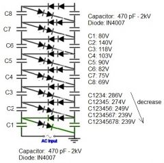
I used Multimeter to measure Voltage across capacitors and here is the result:
C1:80V C2:140V C3:118V C4:103V C5:90V C6:82V C7:75V C8:69V
It is understandable due to lost energy.
But when I measure accross C1C2C3C4, it is 286V (not equal to 80+140+118+103). And Voltage C1234 > C12345 > C123456 ?? why does the voltage drop?
Could you suggest anyway to still increase the voltage? If it like that, the maxium voltage along the whole stages is just between C1 and C4 ( 286V ) only
Thanks
Using bigger caps, or a higher frequency will increase the output current.
I’m making voltage multiplier circuit like this:
http://en.wikipedia.org/wiki/File:Stacked_Villard_cascade.svg
It should gain 2-5 VAC into zener-limited 13,6VDC to charge battery. It comes into a very small wind turbine..
I’m using 0,15V forward voltage scottchy diodes, but I don’t know how to calculate appropriate capacitance for capacitors.
I tested it with 1uF caps and on idle it gives 40VDC, but short circuit current is only 2mA, which is 1/100 of generators short circuit current.
I assume that bigger capacitors would pass through bigger currents, but how can I calculate right capacitance?In a case where:
Frequency is 100Hz
generators internal resistance is 16ohm
short circuit current 200mA
I want to maximize short circuit current after multiplier and also current that circuit draws from gen. So can capacitance be calculated like this or how?
X = 1/(2*pi*f*C)
C = 1/(2*pi*f*X), where X is the same as gens internal resistance.
C = 100uF
You must have it wired wrong or be using faulty components. Check your connections again.
I have a project make an negative air ionizer right now and please help me if possible..
I’m using 30 1N4007 diodes and 10nF, 2k capacitors for half wave arrangement, and the source is 240v AC.
Actually I am just following the circuit schematic from this website.
http://www.brighthub.com/engineering/electrical/articles/78220.aspx
Now the problem is my circuit can’t step up to kilovolts but it will keep decreasing to few volt at the output.. does anyone know what’s going on?
The 555 will both sink and source current so perhaps it can work a little. You would be much better off using some transistors and a small transformer to step up the voltage as it would be more efficient.
Are you accounting for the voltage drop rating of your diodes? Each diode will drop some volts which may be significant when you have such a low starting voltage.
Ah ok, well before I saw your answer I hooked up 6 stages worth of the voltage multiplier and it managed to boost the 555 timer’s output of 14V to around 70V, which is what I was hoping for. Since it’s outputting DC pulses I’m not sure how this is happening, but I was originally under the impression that the 555 timer outputted AC current in a square wave. Obviously, as you said, the circuit isn’t operating properly because with 6 stages I shouldn’t be getting just 70V with 14V input, according to the formula 2*number of stages*input voltage that I’ve seen on multiple sites. What would you suggest to produce AC then, if the 555 timer won’t do the trick? And I’m using the circuit to generate a voltage high enough to charge some larger capacitors fully which will be discharged into a coil for a coil gun. I know this isn’t a great way of going about it, but I’m just starting out and I’m making due with what I have.
The 555 outputs DC pulses so it will not work. Are you wanting just a reference voltage or does it need to supply some current to a load?
Hey there, I’m building a voltage multiplier circuit that deals with low voltages, around 10V input and hopefully 70V output. The exact numbers aren’t too important, but I’d like to know if it is possible to use a basic 555-timer operating in astable mode alone to drive my multiplier circuit, or if I have to use some kind of transformer in between the two circuits. I haven’t decided on what capacitors and diodes to use yet, but I have some 10uF 100V capacitors lying around and some diodes that are rated for 440V and so I tested them out. I set up my 555-timer to output 6.8kHz AC as shown on this site: http://www.kpsec.freeuk.com/555timer.htm
and tested the output on an oscilloscope and it worked fine (approx. 7.1kHz), but when I connected a 2 stage voltage multiplier circuit to the output, there was only about 7V between the multiplier circuit output and ground. Are my capacitances too high for that frequency? Or could it be that my 9V battery that’s powering the 555 timer is too weak a power source? Or is the 555 timer alone not enough for my plan? I am planning on using a more powerful battery later on by the way, but figured a 9V would suffice for testing for now. Any help you can give would be greatly appreciated 🙂
The power dissipated in resistor is proportional the current squared times resistance. Let’s say your MOT is outputting 2kV, the current would be 2000 / 220,000 = 9mA
9mA2 x 220k = 18W.
If your resistor is not rated for enough power, it will melt.
Please see this page, for more such calculations.
Also Sourcing resistors for a voltage divider has been fairly impossible. I made one out of a 10w 220k ohm resistor and a 220ohm resistor. When I attached that to my mot (I tested it to see if there’s high current using really skinny wire, but the wire didn’t burst into flames or even heat up) the 220k ohm resistor exploded. Any suggestions would be great.
I need to make at least 100k volts from either 120v ac or two mots at 2000v each. Whether the circuit is full wave or half. The circuit will have no load as it’s for a paint gun I’m making. Now just a couple questions on full wave multipliers: whats the rough output voltage equation, and how do the components need to be rated. The smaller the circuit is, the better.
Hi, This question has been asked before several times. Please check above. You must do the calculations yourself to work out what components you need. You can check our high voltage components for parts.
PLEASE HELP ME, I AM WORKING ON VOLTAGE MULTIPLIER, THE INPUT VOLTAGE IS 220AC AND OUTPUT OF THE MULTIPLIER IS 150 KVDC. I WANT TO USE HIGH FREQUENCY SWITCHING DEVICE WITH FERRITE CORE TRANSFORMER TO RAISE THE INPUT OF //MULTIPLIER TO 10KV. WHICH DIODE AND CAPACITOR CAPACITIES SHOULD I USE. DO YOU HAVE IN YOUR STORE. MY EMAIL IS lagunna788@yahoo.com
You connect one terminal of the multiplier to the grounded centre tap, the other to an output. Yes measuring the Vdrop will allow you to calculate current
Dear sir/madam,
i would like to ask again, hope sir/madam can reply me as soon as possible because it is urgent. For the last two post, u answer this “Also for the input you should be using the centre tap and one of the other outputs from the transformer.”
what do you mean in this sentence? can you explain me again? thanks
And one more thing, the load is add to output for calculate or measure the output current? measure the voltage drop across the resistor, use the value before minus the the voltage after across and then calculate with ohm’s law??
thx for replying
The load is whatever is connected to the output of your voltage multiplier. It draws some current from the supply.
What do you mean add load? For the purpuse to step down the current?
Yes 2 of each. The 1n4007 only drops 1.1V so it is not a major problem. Do you have any load on the output? Also for the input you should be using the centre tap and one of the other outputs from the transformer.
Dear Sir/Madam,
For one stage of Voltage Multiplier is using 2 capacitors and 2 diode right? I am having a problem after it successful step up on first stage and second stage it decreased. my capacitors is 104(630V)adn diode is 1N4007. The input is using center-tapped transformer, and which provide 15VAC. Is it i am having same problem with mr. Li Yun Lim?? The diode cant work nicely because of the low input voltage??
Thank you.
Yep.
Please let me know if is possible to connect 2 or more high voltage multipliers in parallel ….
The idea is to using capacitors that I have around in my backyard workshop and not to buy others,and increase the output amperage….
Also,however, will be interesting to know if is possible .
Capacitors don’t really have an amp rating. When empty, they will have a very low impedance to the flow of DC current. When charged they have very high impedance. You should’t try to measure it like you suggested, it just wont give you any useful result. you need to calculate its capacitive reactance (in ohms) and then divide your input voltage by this to know the AC current that will flow. I suggest you read this Introduction to electronics.
I understand,is recomended to using diodes at twice amperage/voltage ratings of the capacitors.
How to find the amperage rating of the cap?Is not clear for me.
I have reading somewhere ,to find this,
must conect the cap with an ampermeter in series at the power source to find how much current will flow through cap.
I tried this with an electrolitic cap ,and hocking it in one way at the dc power source,no reading on ampermeter ,in another way my cap has exploded .Conecting it at the Ac source ,I think the cap will blow up anyway
Here is their words;
“
These plans use the old Diode and Capacitor Method, Turn 120 vac. into 25,000 to 50,000 volts DC
earth shaking power! Amperage depends on what size capacitors you use. The higher the micro fara
the cap, the higher the amperage rating. Use an AC amperage meter on the input wire, once you find
how much amperage the cap is rated at, use diodes 2 x’s higher that rating, Example: 200 uf x 360 v
photoflash capacitors will use about 3 to 4 amps max, so you will want to use diodes rated at 6 to 8 a
400 to 450 volts. If you exceed the rating you can cause a fire hazard or a cap or caps can blow up!”
Do you know more about this metod (by conecting the cap at the power source directly?)
Maybe I missed something from that paper.Please give me more details,(to help me to understand), about how to find the current rating of an capacitor using the metod described above or/and another useful method .
Thank you
The inverter / multiplier circuit will generate a lot of electrical noise which may interfere with sensitive electronics like the GPS. It could go on the same PCB, but you should try to shield the GPS. Maybe having the circuits on the opposite sides of a PCB and separated by a ground plane would do it. You would need to encapsulate the HV parst in resin too. Adding an earthed metal enclosure around this part (except for where it touches the animal) would prevent it from radiating noise.
Thanks a lot for this great information.
I am working on a project for fencing grazing animals by use of invisible fencing. GPS positioning is used. All necessary equipment is inside a box connected to a collar. When the animal is moving outside the boundary, a warning sound is emitted, followed by a electric shock.
This shock is why I am posting this question. I am using a DC voltage from a LiIon battery (~4v) this voltage is turned into 600v AC by use of a photoflash transformer. A voltage multiplier is increasing this voltage to about 10kV. This circuit will be powered in less than a second at a time.
Everything OK so far.
But do you think this circuit could be integrated into the same PCB as the other components? (microcontroller, GPS module and so on)
Or should this HV circuit be separated, and placed into a separate housing of some kind?
Yes it can run from the mains. Larger capacitors mean larger current.
I want to run this circuit from standard american wall socket with 120v 60hz. Would this work?
How do I know the current consumption of this device? So I can pick the fuse. Do I need to limit it with a resistor.
What does the capacitance of the capacitor effect? More uF, more what?
I want to be cheap so I don’t want much overkill.
Thanks.
Can i run this circuit off the 120v 60hz?
(American socket voltage/frequency)
What does the capacitance of the caps effect? More capacity, more power or what?
I want to be cheap. Why pay more?
Do I need to limit current at entry?
What current will it consume so I can fuse it with the right fuse.
You can get a type of vero board with no tracks. you ca use this for mounting and just make connections with wires.
The resistor is calculated using ohms law:
R = V/I
If you are just making an ion generator then using smaller capacitors would be the best way to limit current.
Yes, you could use the transformer to test it.
Hey!
I want to build a negative ion generator. I got a bunch of components from a friend. 1N4007 diodes and 1KV 0.1uF film capacitors. I’m thinking about building the full wave rectifier since it will require less stages to get the voltage up to a proper level.
There are a few aspects I’m not sure about:
I was thinking about taking a board, sticking nails into it and solder the components to that board since building this on a VERO board is probably a bad idea since the small gaps between the tracks will cause arcing at some stage.
Second thing, what resistor should I place to limit the currect? I know this is related to output voltage but how do I calculate that anyway? (I have no electrical background at this time)?
3rd, the amount of caps in this circuit means a big in-rush currnet, how should I limit these with a resistor at the input?
4th (and last). I would like to test this thing before connecting to 220V. I have a 65-0-65 transformer. Can I hook the two 65 outs to one side and the 0 to the other side and connect the input to the wall ground (since the transformer has 2 inputs). will that work?
Thanks and keep the good work on the site, great info here!
maloff01,
When making sparks you will cause voltage spikes which can damage the dimmer circuit. You need to protect it using a MOV.
Rolando,
You should use a diode with a higher voltage rating. More information including calculations can be found here
Jack,
The voltage is between the output and ground. AC input, DC output. Please read the page linked above for more information.
I’m a little confused. I want to build a half-wave multiplier, but I have a few questions: In the picture it looks like there is only 1 input, so do I need to make 2 multipliers if i want a positive and negative output. Also does it have to be a AC input. (I want a DC output)
Thanks,
Jack
In my quest of doing the ionizer I fund an inverter from a scanner lamp. From 9v dc I generate 450v ac… I want to have an input of 12v dc, please, could you tell me if the 4007 diodes would work ok with an estimated 700 input volts? If so, could you tell me what capacitors should I use and how many stages on the multiplier to make a simple ionizer of about 5-8kv?
Many thanks for your web site.
Hi I am wanting to make a CW multiplier for use with powder coating. I am wanting to achieve a negative output of 50-100 kv. The circuits are simple enough but I am not sure of what values the caps and diodes should be. I built an ignition coil multipier with a dimmer switch,and 2 300v-1.0-0+25% caps. I powered it with 120v ac. nice sparkes until the dimmer switch lost most of its life. The ignition coil also seems a little unstabe for my purpose. Any help would be appreciated.
Dear sir,
is the ionizer can help healt care?
Is the ionizer hazardous to other electronics equipments?
Is the ionizer like your design applied or similar with ” Dr JISM healt care equipment “?
Thanks
They are about 15mm x 10mm. I am looking for a new supplier due to changes in exchange rate between GBP and USD. I am crrently in China and hope to find some to bring back, but that will not be until Aipril.
It seems you are out of HV capacitors =/
I need to purchase about 20 or so 15kv capacitors from ya for a 200k multiplier. Any idea on when you will get more? Also how large are these capacitors as in size not capacitance from the photo they look pretty small but I cant be sure…
Yes it will still work. The output voltage of an ignition coil is proportional to the rate of change of current at the input. If you apply half the input voltage, the current will half too.
Another possibility would be to use a high frequency. If you use one higher than the coil is designed for, the inductance of the coil will limit the current and therfore reduce the output voltage.
Yes we ship worldwide. If you go through the checkout process, the conversion to USD will be shown before you have to commit to payment.
Thats great! but do you think the ignition coil would still function properly with a lower starting voltage?
also do you ship overseas because I am in America and I dont know how the currency transfers lol
You could possibly use a voltage divider, allthough it might be hard to calculate the correct resistor values.
The easiest way would be to use a lower input voltage.
Hello again,
I am trying to find a transformer (auto ignition coil or other) that will step up my 12v from the pulsed dc circut to 6k volts for the multiplier. BUT it seems i cant find one for that low of output voltage haha. Any suggestions?
Thank you for your advice. I would just like to add that I am simply trying to make a device for self defense, not a weapon.
Regards,
Des
I can’t advise you on making weapons, only science. Multplier circuits need to be potted in some sort of insulating resin for best results and saftey.
Smaller capacitors will give faster spark rate but each spark will be of lower current.
Correction/comment on previous comment:
The capacitors in the circuit are 2 type 2J333J and 2 type 2J223J. They are not all 4 identical.
I have 2 102Z/2kV capacitors. Can these be used for the additional stage in the multiplier circuit?
I am trying to construct a stungun-like device from an electric fly swatter- something like this: http://www.instructables.com/id/cheap-taser-from-fly-trap-rocket–1500-volts-
My circuit is identical to that one: a voltage quadrupler on the transformer’s output, resulting in around 1500V DC (not bad when powered by 2 AA batteries). The capacitors are type 223 and I can’t tell the diode type (1N4007’s?).
I was thinking about adding an additional doubler, multiplying the transformer’s output 6 times instead of 4 (there’s no room inside the handle to add a transformer to multiply cap discharge by 100-500 times via a neon bulb/spark gap and I want to keep it simple, but effective), then using a 9V battery to power the circuit.
Questions:
Would I need to insulate the circuit (with silicone or so) to prevent sparks jumping between the diodes/capacitors on the circuit board (I tried adding a 9V battery from the start & created a big spark on the circuit board while charging up the capacitors)?
And how can I control the current at the output (need about 3 mA)?
And if I want a very rapid cycle at the output, I can simply use smaller caps for quicker charge/discharge times, right?
I want the device to work like a stungun, incapacitate, not kill a person.
Yep
hello, I think the 6A10 DC diodes rated for 1kv will be fine. right. (I want to apply input 200 V AC)?
Voltage drop makes a huge difference to the actual voltage you will get at the output.
quote from this forum:
“With 13 stages and 220V AC input, the output should be around 2.5kV. This voltage will only cause sparks to jump a few mm at most.”
Other site:(http://www.kronjaeger.com/hv/hv/src/mul/)
An n-stage cascade produces 2n x Up output voltage.
Please explain.
Yes, but using lots of little A23 cells seems expensive. A small 12V SLA would be best.
Hello I love your website its very informative!
I was wondering if it were possible to use a bunch of stacked A23 12v batteries (connected for more current), to power some sort of pulsed dc or frequency generator to step up the 12v to hv through an auto ignition coil in order to drive a halfwave series multiplier?
There are a few experiments Id like to preform and these experiments require odd ways of powering a multiplier hehe
The 3kV capacitor would be destroyed by the plasma globe output.
If your plasma globe power supply is being damaged, it is possibly overheating due to being overloaded. You could place a 10M resistor on the output of the multiplier to limit the current.
Hi, im building a five stage, half wave multiplier, powered by a plasma globe PSU. Iv followed all the directions detailed above and somthing has gone wrong. Iv gone through two PSUs and the thing just wont work. I bourght the 30kv capasters and diodes, (the ones you stock in the shops). The PSUs were not maplins stock (sold out with christmas returns) and had a 3kv capasator on the end of the out power cable. it worked for a wee bit then stoped. do you think my problem is using higher rated components or is it a lower spec PSU? i thourght all Plasma globes were simerler power due to the coronas critical voltage in argon? please help. thanks.
Type your message here difference between full wave diagram and half wave diagram
Hi
I would like to generate a high voltage ( 10kv) low Milli amperage device for producing an “Electret self charging capacitor”. These devices need a constant hv low amperage device attached to them during production. Could you please advice on the number and values of components needed
Hi, new project and a couple of questions in preperation:
im about to build a 10 stage half wave multiplyer as an add-on for the plasma globe psu with possable switches at every 2nd stage for a varing output. would the high voltage capacitors (30kV) and Diodes (30kV) be able to take the power at the higher stages? would i need to worry much about cooling? what switching gear would you suggest? oh and what do you guys reacon the output ampage of the PSU?
thanks and a bonny christmas to all.
Sir,
Thanks for answering my quetion,i still need your help.Please,can you send me the schematc diagram of voltage multipler,with the capacitors values?
Thanks and God bless you.
If you use high speed oscillators remind that 1N4007 is not a fast recovering diode but ok for 50-60 Hz
the voltage over a multiplier vil drop if ther is to many steps, it can be corected by butting a resonator in top or middel of it
if voltage goes up 2 times, amps will go down 2 times.
I have 10 cap 390V 400uf half wave multiplier. I have 340 688 900 and etc outputs. If I load 688 output with only 0.5A load voltage drops to some 480-500V. I drive pulsed dc motor. It seems I can use even the last output wich without load shows 1700dc and it still drops to 480V under 0.5A electric motor load. Why is that? I tought this multiplier suppose to provide more amps without sucha voltage drop.
Hi, im making a high power negative ionizer and I want to know the output. Im using 30 x100nF capasators and 30 x1N4007 diodes in the half wave arangement. if you could give me the equation it would be bonny as i cant seme to find it. Thanks
In the full wave multiplier you dont need the center capacitor
The current rating of your diodes would depend on the frequency used and the capacitance of the capacitors. If you are using small capacitors then only a low current rating would be needed.
i found this site very usful. very great site.
i have confusion in selecting current rating of diodes in voltage multiplier 100 kv. i want output current of multiplier 100 micro amp. please help me.
If you are using 1n4007 diodes, the 15kV caps are probably overkill. You could save money and space by using ones rated for just 1kV. More detail or a circuit diagram would help me answer your questions.
Thanks for all your advice. Your experience has helped me quite alot.
My plan is to drive the Greinacher (CW) Multiplier with as little power as possible so a CMOS 555 (astable 2kHz) will trigger a fast-response-time capacitor driven photo-MOSFET NAIS(AQV258) cathode switching the output of an EMCO G30CT (Center-Tapped 1500Vmax) DC to HVDC converter. My intention is not to discharge the circuit but rather to use the potential field it generates. For this reason I chose 470pf 15kV Caps and 1N4007 Rectifiers. Using your ball park calculations puts it at 8.9mA which should be okay. I am not sure how the resonant coil in series with the CW input would affect this.
My questions are:
Will I get by with a second AQV258 for the negative output of the G30CT or is an H-bridge the answer? I was thinking of a both a positive and a negative half wave multiplier for each of the G30CT outputs. Does this seem feasible?
hello ive bilt it in a pvc tube, the input is 12vac and out put is 85vdc the bulb is a 240v 40w bulb it dosent overheat the caps and diodes
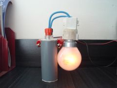
thankyou i have bilt it for a valve amp ht line it works very wel. its better
than a magnetic transformer, i wil designe it for 3 phase, i have a big 1950s signal generator and a collection of 29 old valve radios i shal send pics later
The caps used should be non-polarized so it does not matter which way around you put them. If there is no marking for positive or negative on the ones you have, you can assume they are non-polarized.
hello wich way dose the caps need to be
Hi I am building a 80kV multiplier. I am looking for approx 1A output, thats right you heard me, 80kW. I plan on using the popular UX-FOB diodes, and I am looking for fastest rise time possible. How can I calcuate capacitor size required for this output? Also how can I calculate the rise time to 80kV based on various different combinations of input voltages to the multiplier & stage combinations. I also plan on running this faster than 60hz. Sure I could do it by trial and error, but I was hoping to save some time.
The 50V rating of your caps only limits the input voltage you can use. Add more stages to get more voltage.
hi… i am suppose to build a power supply using voltage multiplier
my task is to achieve around 1kV
but I am only getting around 500+V
so what i wanna ask is if my capacitor voltage rating is 50V, will it limit capability of voltage multiplier?
thx alot
The voltage drops are the same at each stage. I can’t suggest values for you. They depend upon what you want from it and what you power it with. Read through all te comments on the pages about voltage multipliers for some examples people have used.
i’m very curious about the behavior of the capacitor and other parameters regarding the circuit.
Is the voltage drop across each capacitor varies at every stage?
i made 2 units of voltage multiplier. this is an air ionizer, One is using this components: 104J/630 V Mylar Capacitor, with a IN4007 diode.
The other unit has a capacitor rated 104K/630V Mylar capacitor with the same rating of diode as the first unit.
I’m really begging to you, will you help me for some computation proving for suitable rating of the components to be used? thanks! good day
MOT is approx 1.5kV. The are incredibly dangerous because of high current output! I recommend not using one.
We have HV capacitors and diodes if you need them.
how well will this work if powered by a microwave oven transformer (est 6 KV)
and using 10 stages for a HV lifter but i am guessing that the caps and diodes will be a bit hard to get.
No. A voltage only appears on the output of a transformer when the input current is changing. A square wave input would give you a high frequency pulse on the output during every hi-low transition of the input waveform.
if you use a square wave vin to your transformer do you get a square wave out? i guess it would run a multiplier as a square wave is like a half sine wave.
See this message. Before building yourself a multiplier I suggest you draw or print out a schematic and try to visualise how the current would flow through the circuit.
Again the last question is how to select proper voltage of the diodes for voltage multiplier?
For Example if you goin to use:
220 input AC and Capacitors 400v 100uF,reactance is 32Amps so Max current will be 8 amps.
what is the max diode Rev. Voltage we are going to choose?is 600V enought?or do we have to count capacitors as series I am bit confused about your last reply (‘A multiplier charges the capacitors in parallel and discharges them in series’) and sum the total voltage of the multiplier? of course to find out proper nad safe Reverse Voltage of the Diodes? Thank you again
Capacitors like these are usually used for creating a large current pulse.
The current you calculated would only be drawn for a brief instant because the capacitors will charge up and draw less and less current. This current would only be continuous if the output of your multiplier were shorted. You should use only very small capacitors for a multiplier, especially if you are not experienced with such devices. Nano or pico farads would be much safer.
The voltage rating of your capacitors must be at least that of your supply voltage (220V)
A multiplier charges the capacitors in parallel and discharges them in series. From the output pov, the capacitance is calculated as 1/Ctotal = 1/C1 + 1/C2 ….. From an input pov, the capacitance total is the combination of all added together.
Is it mean that would not be possible to find use of my 400V 470microF Capacitors?So the biggest capacitors I can use are with less 15microF? Am I right?Then I get less than 1.03686Amp with 220V input?Is it matter what voltage of capacitors I will use what is the relationship of that with input voltage?If i am assuming correctly Voltage mutiplier connects capacitors in series not in parallel so the capacitance will be reduced significantly along C=1/C1+1/C2+1/C3…the same as Amps
470 microfarads is pretty large. Your calcs show the current in one cap if it were placed across the supply. You would be charging 10 capacitors in parallel which would probably trip out your inverter. You would need to limit the current drawn from it by using a smaller capacitor in series.
A common diode for a multiplier would be the 1n4007 but you would need to limit current to under 1A.
Hi I have got quantity x10 capacitors 400V, 470uF.I would like to build full wave voltage multiplier.
The input is from 150W(max peak300W) Inverter 220V AC(usually gives 208V AC)
is that correct way to find out?
I am not sure… i get Reactance for capacitors 470uf 400V
1/(2×3.1415x50x0.000470)=6.7725
from Ohms Law
I=32.49Amps???
P = 7260W???
What do you think?
I would appriepriate your advice ,what type and ratings of rectifying diodes should i use for that project?
Thank you
Thanks for pionting this out. I think this part was quite badly explained. The diode will drop 1.1V if the current is limited to 1A, but at the first instant if the diode is froward biased by the input, the majaority of the voltage will be dropped across the diode because it is essentially acting as a short circuit until the capacitor has charged up a little.
QUOTE:”To suggest that the 1A diode can only pass 0.0114 amps just because the signal applied to the overall circuit is 220V is ridiculous.”
Of course. It should have been made clear that this was refering to the brief moment where the voltage appears between the diodes terminals when forward biased.The original post has been updated.
Regarding the quote below… There are some problems!!! The 1.1V specification is for a forward biased diode. Meaning the current is flowing through the diode the “proper” direction. And, the rating is 1A, which leads to your 1.1W of power dissipated in the diode, within the 2.5W maximum spec. All hunky-dory so far. HOWEVER, once you launch into the 220V stuff you are off a bit. Applying a 220V forward biasing signal will result in no more than 1.1V of forward drop across the diode, with the other 218.9V being dropped by whatever else is in the circuit. Even under these circumstances, the diode can pass up to 1A. Now, make it a reverse biasing 220V signal, and the diode will pass essentially zero (0) current, and will dissipate essentially no power. (There is always a leakage current, but it is quite tiny.) Your ohm’s law analysis is flawed. The 220V signal is irrelevant, so long as it is less than the RMS specification of the diode, because the diode is only dissipating power when forward biased (and at that no more than 1.1 Watts), and when leaking reverse current (certainly far less than 1 amp). In fact, the reverse current with associated power dissipation is to be considered negligible from the thermal standpoint, so long as the reverse voltage does not exceed the specification on the datasheet.
To suggest that the 1A diode can only pass 0.0114 amps just because the signal applied to the overall circuit is 220V is ridiculous.
QUOTE:
1.1V @ 1A is eqivalent to 1.1W of power. The absoloute maximum power rating for the 1n4007 is 2.5W.
If you were to apply 220V @ 1A to the diode this would equal 220 Watts! Your diode would not lke that at all.
To see the max current you can use with a 1n4007 you can use Ohms Law. If P=2.5 and V=220 then the current would be 0.0114 Amps.
Cheers,
SailorThor
Hi I have got quantity x10 capacitors 400V, 470uF.I would like to build full wave voltage multiplier.
The input is from 150W(max peak300W) Inverter 220V AC(usually gives 208V AC)
I would appriepriate your advice ,what type and ratings of rectifying diodes should i use for that project?
Thank you
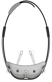
hello…i want to make pika shoe that found in this link
(http://afrotechmods.com/cheap/negativeiongenerator/pikashoe7.htm
and im gonna use a homemade ionizer as substitute for 12v dc negative ion generator and put an inverter as what you told lately
in this link the instruction for making the ionizer
(http://www.emanator.demon.co.uk/bigclive/ioniser.htm)
pls i am an magician electricity is a big help
what is the no. of capacitor and diode should i use…pls help me…12v dc negative ion generator is not available in our country so i decided to make a homamade one….
I’m afraid I can only recommend that you don’t connect any high voltage device to your body. Especially a home made one.
Trying to charge your body will be quite lossy (charge will leak off into the surroundings) so this means that there will be a continuous flow of current through your body. It will only be small but it’s probably not that good for you.
A sparse (widely spaced) wire mesh or just the stripped and spread end of stranded copper wire in front of the fan would be adequate as an ionizer.
hi!!!
what is the number of diode and capacitor you recommend to use in my project about the ionizer that attach myself….what kind of needle i must use and how many needles i gonna use? thanks
Hi can you help me? I am desperately looking for advice. I would like to build high voltage power supply. The input is 220V AC (from 150peak – 300W 12V to 220V inerter)
I have lots of electrolytic capacitors 400V , 470uF. I am going to build following voltage multiplier, But I found it difficult to establish diodes rating, what sort and what rating of diodes will be the most suitable for that solution? (10Amp 600V???)…
I know only I have to use rectifying diodes rated twice the current, but how to find out what current will be in the following caps.?
1.1200V DC (3x400V Capacitors)
2. 2000V DC (5x400V Capacitors)
3. 2400V DC (6x400V Capacitors)
4.3200V DC (6x400V Capacitors)
.I would appropriate any advice
Please specify the diode ratings and type
Thank you
Regards
The actual number of -ve ions would be hard to calculate. It would be a factor of voltage, current, air temperature, humidity, air flow, and the shape and size of the electrode which is in contact with the air.
thanks for your reply….how could i calculate the negative ion output?….i decided to make 10 stages…(20 diodes and 20 capacitor)… my inverter is not for cold cathode but it still convert 12v to 220 v ac…
No. All the components need to be rated to at least the peak input voltage. If you put 1kV AC in, all the capacitors and the diodes need to be rated for at least 1kV.
thanks…so you mean in my project i will use HV diode and low voltage capacitor
Some HV diode numbers:
BY8418 – 22kV
BY8414 – 17kV
We also have some 20kV Diodes available
2 diodes and 2 capacitors make a single stage of a half wave multiplier. The output voltage (very roughly) is proportional to the input voltage x the number of stages.
If you use a cold cathode inverter which converts 9-12V DC into about 1kV AC, 10 stages will give you about 10kV DC at the output.
It is important to note that it is the current that kills and not the voltage of an electric shock. The capacitors used in a voltage multiplier store energy and can therefore release large pulses of current. Smaller capacitors are cheaper and safer. It would also be wise to connect a current limiting resistor on the output (about 10M ohms).
hi!!i want to make a pika shoe how many diode should i use???
Can you tell me some(part number) of the diodes that can handle about 15-20kV? I want to use this multiplier circuit with 15kV input.
The capacitance value used just depends upon how much current you want it to deliver. Smaller capacitance means smaller current.
what is the uf on the compasitors?
(sorry for the misspelling)
You will need to buy some High Voltage Diodes
my diode is only 100v…what shall i do?
This is as simple as it gets. Apart from buying a ready made one!
Don’t make “strong” HV device and connect it to you body. You will probably die or be injured like this guy
hello can someone give me a simplier instruction to build an strong 12v dc negative ion generator
i want to build pika shoe found at this link
(http://afrotechmods.com/cheap/negativeiongenerator/pikashoe7.htm)
Does anybody know how to calculate the rms current of the diodes and capacitors on a Voltage Multiplier circuit? (dee6neg@joinville.udesc.br)
The output circuit is completed by the ionized air. Once ionized, the air mollecules become mobile charge carriers much like the electrons in a piece of wire.
Most of the ions are quickly neutralized by other air mollecules therefore you don’t often see then reach the ground.
Hi.
I enjoy this site and am enjoying learning about voltage multipliers. Your explanations and examples have helped me understand the multiplier itself, but what I’m having a problem with is understanding it’s connection with the mains, on the source end, and the load on the output end.
For example, I have been studying all the pics and descriptions I can find, including the info at:
http://www.emanator.demon.co.uk/bigclive/ozone.htm
http://www.emanator.demon.co.uk/bigclive/ioniser.htm, but I don’t understand if the hot and neutral and ground are connected to the multiplier, how does the tubes in the ozone generator example, get supplied from the mains neutral, as stated?
Also, if there is only one output from the DC end of the multiplier, and assuming that is neg. voltage, where does the positive voltage come from (i.e.: how is the circuit completed for anything other than an ionizer)?
I’m asking because I am interested in making my own ozone generator by using a mains powered voltage multiplier instead of a transformer, and it will be similar to the one here:
http://www.emanator.demon.co.uk/bigclive/ozone.htm
Thank you for this website and all the info.
You just place an ammeter in series with input power source.
If the voltage is too high vor your ammeter, the alternative is to place a low value resistor in series, measure the voltage drop accross it, and calculate the current using ohms law.
Hi,
Is there a way to measure current at the input of the CW-multiplier? I have seen this method at high voltage power supplies. Does anyone know how this is done?
The schematics and info on components are allready on this page. Have a look through the previous comments and links.
Basically you need some sort of inverter to convert 12V DC to an AC voltage. This ac voltage is then fed to the voltage multiplier as shown in the diagrams.
hello.
i’ve been searching the internet for days for proper instruction for making an ionizer…
and then i came across your website.
could you please tell me what kind of capacitors and diods i need to create a voltage multiplier with 12VDC input and 15kV negative output.
i’d really appreciate if you could draw a scheme for me on how it should be connected.
Thank You.
There is a very high voltage output and the circuit is simple but effective!
Well that was a fun project. Thankyou.
A voltage multiplier / quadrupler wil give you a DC output, so I guess it will not be suitable for your application. You can learn more on the voltage multipliers page.
A simple transformer would be the common (and more efficient) approach to AC-AC voltage conversion.
Hello,
I was interested in building a Voltage multiplier for a power supply, that will have roughly 208 VAC going in, and need 800 VAC going out. So I’m guessing I will need a Voltage Quadrupler.
Is there a schmatic diagram available for this? And what kind/how many of Diodes and Capacitors will I need?
Thanks
The input and output current will vary with time and loading conditions. It can be difficult to calculat and it depends upon a lot of factors. The info above should help and you can also find more complex calculations on the Blaze Labs website.
How do I calculate the total current? thanks
See the 1n4007 datasheet for more info.
EDIT:—–
If the capacitors used are too large then when the inpult votage is applied there will be a low impedance to the flow of current. If the polarity forward biases the diode it will cause a large voltage drop across the diode (because the diode and cap are basically shorting out the supply at that instant of time) thefore causing it to draw lots of current and heat up.
The 1n4007 will withstand 1A contiuously and more if it is only for brief moments.
—–
The current flowing into the circuit is limited mostly by the impedance (capcative reactance) of the capacitors. The AC input passes directly through a capacitor at the input end and you can calculate its reactance with the following…
X = 1 / (2 * pi * f * C)
Where X is Reactance in Ohms
pi is 3.142
f is frequency
C is capacitance
So at 50Hz with a 10nF capacitor there will be 318310 Ohms of impeadence to the flow of current.
Roughly speaking (ignoring RMS conversions etc) you can calculate the maximum curent flowing through a single 10nF capacitor using Ohms Law.
I = V / R
= 220 / 318310
= 0.69mA
Although this does not give you the total current flowing through your diodes, it will hopefully give you an idea of how the scale of the different variables will effect some of the elements in the circuit.
The simplest way to measure the current is using a standard multimeter. with the mutimeter in current mode, its leads can be connected in series with a diode to see how much current flows through it. Obviously all power should be switched off and all capacitors dischraged before connecting or adjusting the multimeter.
Thanks a lot! I thought the 1N4007 would allow 1A, are we likely to have more current than that? And how could we measure the current safely on this circuit?
– great site by the way, will try to build your Tesla coil as well!
Thanks, Happy new year. The type of capacitor dielectric or casing is not of great importance here. Those factors are only generally considered when using the caps in signal processing circuits or an accurate PSU.
I’ve used resin dipped ceramic types because they are compact, low cost, and come with a range of high voltage tollerences.
Could you please put some light on the capacitors to be used for this?
MLC or Polyester as both have high voltage ratings. Also, a Radial, axil and potted box types are available. Which gives better results?
I would like to use it for 220 V AC, 50 Hz.
I also take this oppurtunity to wish you and your near & dear ones a very happy new year and a successful too.
It sounds like your device is working ok. With 13 stages and 220V AC input, the output should be around 2.5kV. This voltage will only cause sparks to jump a few mm at most.
The ion wind generated from a single needle will only be very small @ 2.5kV. Multiple needles will help, but only up to the point at which they draw the maximum output current of your multiplier.
The amount of ion wind generated is proportional to the current flowing through the needles. To increase the current flowing through a single needle, the voltage applied to it needs to be increased.
To increase the current available from a voltage multiplier, the capacitance of the capacitors needs to be increased.
If you increase the size of your capacitors significantly, it may be neccessary to use a larger diode than a 1n4007. Maybe a P600J would be able to handle some increase in current.
I am trying to build an ion generator using your design (and also refering to http://www.emanator.demon.co.uk/bigclive/ioniser.htm)
I used 26 1N4007 and 26 10 nF, 1kV capacitors plugged on the main (220V – and am very careful!) but only get a very very small spark (3 mm) between DC out and Ground (using 2 needles). I could also charge dust specks etc. Any reason this is not generating an “ion wind”? many many thanks – Thomas
Used motor oil is not reccomended. The oil will bw full of carbon and metals particles which could reduce the insulating properties of the oil.
As stated above – “….all components should be rated to tollerate the full peak to peak voltage of the AC input.”
There’s no average flourescent light ballast as far as I’m aware. I think you are misunderstanding the purpose of them anyway. They are not used like transformers for changing voltage, but they simply limit the current to the flourescent tube. Therfore you put 120V in, then you get 120V out, but with a shifted phase.
will used motor oil work as insulation, do the caps need tp be rated for peak input voltage or output voltage, and how much does your average 120 volt flourscent light ballast generate?
Marc
A true AC sinewave is not neccesary, but it does need to be and AC input of some sort.
Pulsed DC won’t work, but you can use a 555 circuit to generate AC.
will the output of a 555-based transformer driver circuit be suitable for the input to a multiplier cascade? or is a true AC-sinewave needed?
Mineral oil is usually used, as it is less flamable than others.
You can use other oils like cooking oil, but these can have lower ignition temperatures and, may also go moldy if exposed to open air for a long time.
hi, what type of oil is recommended to use to provide HV insulation for the voltage multiplier circuit? thanks!
I can see why this could be confusing. The problem is that The input is AC and the output or the voltage across the capacitors is DC. The AC voltage and DC voltages are not directly comparable.
You should take the values as rough guides. It is always a good idea to use components that are rated higher than the voltage / current you are expecting to expose them to.
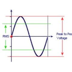
AC voltage is usually given as an RMS (root mean square) value, which is a sort of average over a full cycle. When using a half wave multiplier your capaciors only see half of the peak to peak voltage, and therfore do not necessarily need to be rated to a DC equivalent of the RMS input voltage.
The diodes on the other hand could be exposed to the full peak to peak voltage when AC cycle is of opposite polarity.
With the full wave multiplier all components should be rated to tollerate the full peak to peak voltage of the AC input.
Yes you can connect capacitors in series to increase the voltage tollerance, but the capacitance will be reduced.
You can also connect diodes in series to increase the voltage tollerance, but there can be problems caused by slight differences in recorvery times of each diode used. It would definatley be better to use adaquatley rated diodes.
In doing research on voltage multipliers I’ve run across information that seems to be conflicting and I was hoping you could clear this up for me.
Here’s a few references that seem to be in conflict:
From your site:
https://www.rmcybernetics.com/science/high_voltage/voltage_mult.htm
“The biggest advantage of such circuit is that the voltage across each stage of this cascade, is only equal to twice the peak input voltage…”
From the forum here:
“Your componets are only exposed to the STAGE VOLTAGE so if you are only applying 220V AC the components only need to be rated as such. 700V is more than enough since you are only applying a maximum of 220V AC to each component.”
From another site:
http://www.powerlabs.org/cascade.htm
“The output voltage (Eout) is nominally the twice the peak input voltage (Eac) multiplied by the number of stages”
From your forum:
“…this outputs about 800V from a 9V battery, so adding three multiplyer stages would give you about 2400V.”
If your site is correct then V_out = V_in * num_stages
If the other site is correct, then V_out = V_in * 2 * num_stages
The other thing in question is whether the components need to be rated for just the input voltage, or twice the input voltage.
Specifically, what I’d like to do is to use a 10kv AC input source to power a full-wave multiplier cascade so the theoretical output voltage is 1 million volts. Obviously this is a large undertaking so I need to really know how many stages and what rating the components need to be.
Another question I have is that since there is a dramatic price difference between ~4kv capacitors and ~10kv capacitors, is it perfectly acceptable to substitute multiple capacitors in series for a larger rated capacitor? If so, does this also work with diodes?
Thank you very much for your help, please drop me an email matrixbandit(at)gmail.com if you post a reply to this.
The datasheet for the LM2577T has several example circuits.
You can also see an example here.
You can also buy ready made units designed for use as an in car laptop charger
What is the circuit diagram? How do I connect it?
Thank you.
You can use a “Step Up Voltage Regulator” like the LM2577T, but these still usually need a small inductor (coil) and a capacitor coneected to it.
Dear Sir/Madam,
May I know what are the ways to step up a 12Vdc battery to 16Vdc, other than using a transformer?
Thank you.
A voltage divider is the most reliable method, and this is the method used in commercial HV meters.
There are other methods you could use but they will not give you a voltage reading, just a relative scale.
An ‘gold leaf electrometer’ could be made using thin foil instead of gold leaf. This would give an indication of relative charge.
You could also make a ‘FET electrometer’ but the by far the best way is to use a voltage divider.
Dear Sir/Madam,
May I know is there any other way that I could measure the readings of my high voltage multiplier, other than using a voltage divider?
Thank you.
The high voltage output from a multiplier is accross all the components in series so you don’t need your components rated for the output voltage as it is shared between them.
Your componets are only exposed to the STAGE VOLTAGE so if you are only applying 220V AC the components only need to be rated as such.
700V is more than enough since you are only applying a maximum of 220V AC to each component.
The top diode may show 15kV relative to the ground, but the the voltage across the diode between its two pins will be only the stage voltage.
The same logic also applies to your capacitors. The capacitors you have will probably work ok, but ones rated for lower voltages will have a larger capacitance for the same sized component.
Dear Sir/Madam
But the maximum rms voltage IN4007 diode is 700V only and my output voltage is 15kV. Can I still use IN4007 diode? Will it affect or burn the diode? Can you recommend me the rating/type of capacitor to use if I want to get the output voltage up to 15kV?
Thank you.
The components you have mentioned should work OK if you are applying a high enough voltage to the input. If you want to be able to adjust your variac (variable transformer) from as low as 10V then it may be better to use diodes rated for lower voltages.
Your componets are only exposed to the stage voltage so if you are only applying 220V AC the components only need to be rated as such. An example diode might be a 1N4007 or something similar in the series. These are only small so if you need to pass higher currents you should select a larger equivalent.
Dear Sir/Madam,
I would like to step up from 220V to 15kV. What types/models of capacitors and diodes would you recommend me to use to build a voltage multiplier?
Thank You.
From you description I would guess that the problem is that you are using kV rated diodes with only a very low voltage AC input (10V). Most high voltage diodes will not work correctly unless you are applying at least 100V. The NTE517 diode is a high power component and is unsuitable for a low voltage circuit.
Also make sure you are measuring the stage voltages between you ground connection ant the correct place on the circuit like shown in this diagram.
Are you trying to step up a low voltage source to HV DC? If you could explain your objective, I may be able to give you some more advice.
Dear Sir/Madam,
I am designing a voltage multiplier circuit. I started off by building a 2-stage half wave voltage multiplier circuit using NTE517 (5kV) diodes and 1000pF (15kV) capacitors. I connect the circuit to a variable transformer and tuned the variable transformer to 10Vac. My result for my 1st stage is 5.57Vdc and 2nd stage is 3.72Vdc. Why is it that the output voltage is decreased? Are the types of diodes and capacitors used unsuitable? Could you recommend me a suitable type and value of diodes and capacitors?
Thank you.
I made one just like it using the cold cathode PSU. If i stood on a chair (so I was insulated from ground) I could hold the high voltage output without getting shocked. I could then point at things in my room and my finger tip would glow with loads of purple sparks!! Certain objects I pointed at would also glow too.
It didn’t make my har stand on end but I could certainly feel it trying. Cool!