Circuit Examples
Making Electronic Circuits
This page should help you learn about how different components can be combined to create useful circuits. We’ve included a range of example circuit diagrams and explanations of how they work. The circuits start from the very basics and move on to more advanced practical circuits.
Connecting Resistors Together
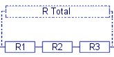 Resistors are commonly used for limiting the current available to part of a circuit, but they are also used together in networks to allow voltages to be distributed how you want it around a circuit.
This is commonly written as RT = R1 + R2 + R4 ……
Resistors in Parallel
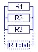 When resistors are connected in parallel the overall resistance is reduced. This is because there are more paths for the current to follow making it easier than just flowing through one device. Connecting two resistors in parallel that are of the same value simply halves the total resistance, connecting four in parallel makes the total resistance 1/4 of a single resistor, and so on.
When connecting resistors in parallel of different values the following formula is used. 1/RT = 1/R1 + 1/R2 + 1/R3
Voltage Dividers
 A common use of resistors is to put them together to form a voltage divider. The term voltage divider (aka potential divider) is quite self descriptive as they are used to divide up the voltage into portions determined by the resistor values.
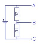
This diagram shows a simple example using a single battery and two resistors. The three points (A,B,C) on the circuit are where the voltage measurements can be made.
If this battery is 10V then the voltage between ‘C’ and ‘A’ will also be 10V. The voltage at ‘B’ is determined by the ratio of the values of the resistors R1 and R2. For example; if R1 and R2 are of the same value then the voltage at ‘B’ will be exactly half the voltage between ‘A’ and ‘C’. The polarity of ‘B’ can be considered as either positive or negative depending upon whether you use ‘A’ or ‘C’ as reference for the measurement.
From this simple example you can have a three rail power supply with outputs of either 10V, 5V, 0V, or 5V, 0V, -5V with respect to A,B,C.
To get different voltage ratios you just alter the resistance ratio. For example; if R1 is 1k Ohms, and R2 is 9k Ohms, the voltage between ‘C’ and ‘B’ will be 1V, while the remaining 9V can be measured between ‘B’ and ‘A’.
Connecting Capacitors Together
Capacitors are used as temporary energy storage devices and are often used for generating or tuning signals. Capacitors can also be connected up to work in the same way as as the voltage divider described above. The formulae used for capacitor networks are similar to those used for resistors but they are used in reverse with respect to series and parallel configurations.
Capacitors in Series
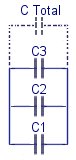
 Connecting capacitors in series divides the voltage between each capacitor in a similar way to how it works for resistors. This is useful for creating high voltage capacitors from a series of lower rated ones. This technique is often used for making DIY homemade high voltage capacitors (known as an MMC) for use with devices like Tesla Coils. When capacitors are connected in series the total capacitance (C Total) is reduced. If two identical capacitors are connected in series the overall capacitance is half the value of a single one. This is usually expressed using the formula below.
1/CT = 1/C1 + 1/C2 + 1/C3 ……….
When making a high voltage capacitor like an MMC, it is common to create several series strings of capacitors to match the desired voltage rating, and then to connect these in parallel.
Capacitors in Parallel
 Capacitors are often connected in parallel to create a larger overall effective capacitance. The voltage tolerance remains the same while the capacitance of the capacitors can be added together to get the total. This is usually expressed using the formula;
CT = C1 + C2 + C4 ……
RC Circuits (Resistors & Capacitors)
An RC circuit is simply some combination of a resistor and a capacitor. The value of the resistor in a circuit with a capacitor will change the rate at which the capacitor can be charged and discharged. This relationship is known as the RC time constant. The combination of resistors and capacitors can be very useful for timing circuits and also filtering signals.
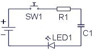 Here a capacitor is placed in series with a resistor and an LED. The LED is simply used to give a visual indication to what is happening in the circuit. When the battery is first connected the capacitor will begin to charge and therefore a current will flow around the circuit. As the capacitor charges the current flow will decrease until the voltage across the capacitor is equal to the battery voltage. While C1 is charging you will see the LED light up and gradually fade out when C1 is fully charged. Releasing the switch will not reset the circuit. The capacitor must be discharged before the process can start again
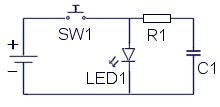 This circuit is the same as before except the LED is placed in parallel with the capacitor. When SW1 is pressed, the LED will light up and the capacitor will begin charging. When SW1 is released, C1 will discharge through R1 and the LED causing it to gradually fade out.
Diodes
 Diodes are used like a one-way valve for electric current. They are often used in converting alternating current (AC) into direct current (DC). LED’s are a type of diode that will light up when it is conducting enough current. Typically this current might be 15mA. When using a battery to light an LED, it is necessary to add a resistor in series to limit the flow of current to a safe level for the LED.
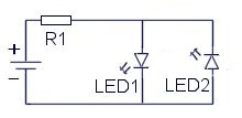
Here you can see two diodes connected in reverse parallel orientation. As shown, only LED1 would light up. If the battery polarity is reversed, the other LED would light up instead. This is because the current will only flow through a diode in one direction.
Transistor Circuits
Transistors are commonly used as a type of switch which is controlled using a small input voltage or current. They come in two distinct and delicious flavours, N-Type and P-Type (NPN or PNP). The N and P represent the type of silicon compound used in the layered construction of the device. They have three electrical connections when used in a circuit, one of which is the input for control voltage or current (gate/base), while the remaining two (collector/drain and emitter/source) are used as the switch connections to make or break the flow of electricity.
The two main flavours (N and P) are also used in three basic recipes known as Bipolar, FET, and IGBT. Bipolar transistors are controlled by varying the current flowing through the base (input terminal) to the emitter. FETs (Field Effect Transistors) and IGBTs (Insulated Gate Bipolar Transistors) are controlled by a voltage applied to the gate (input terminal).
N-Type transistors are switched on when the input pin (known as a “base” or “gate”) is set high. This means applying a positive voltage to the input pin. When activated current will be allowed to flow between the other two terminals.
P-Type transistors are switched on when the input pin is set low. This means applying a negative or zero voltage to the input pin.
The voltage applied to the base or gate is measured relative to one of the other terminals. For N-Type, this is the emitter or source terminal. For example; raising the gate terminal to 10V above the source would switch on a FET, whereas making the gate voltage equal to or less than the source terminal would switch off the FET.
For P-Type, the base or gate voltage is measured relative to the collector or drain terminal. For example; if the gate voltage is equal to or less than the drain terminal, a FET would be switched off, whereas if the gate voltage was less than the drain terminal, the FET would be switched on.
The voltage difference needed for a transistor to fully change state is typically around 10V for FETs and IGBTs, or 0.6V for Bipolar transistors. The exact values needed will vary with whatever model of transistor that is used. The manufactures of transistors supply datasheets for their products so that you can see all the requirements and limitations of the transistors.
The main two factors looked at when choosing a transistor are its voltage and current ratings. They are rated for a voltage at which the transistor can still block (in the off state) without failing. The current rating is for how much current can be allowed to flow through the device without it being damaged. Typically it will be necessary to mount a transistor on a heat sink to keep it cool when switching large currents.
The large current that flows through the transistor when switched on can normally be controlled in one direction only. When conducting, the transistor is like a diode. Many types of transistor also contain another diode built into the device which is in the opposite direction. This allows current to flow through the device in the opposite direction, even when the transistor is off. Typically this diode can handle about as much current as the conducting transistor. The datasheet will show you if the transistor contains a diode or not, and give you all the ratings for it.
Next Page: Cybernetics Menu
Previous Page: Electronic Components
13 Comments
Leave a Reply
You must be logged in to post a comment.
Thank you, I really enjoyed this page
Ok, I don’t understand but if I have your mailing address, which you could sent through the email I provided, I should be able to get someone resident in UK to get a cheque across to you.
Haha, No.
Please A check from me will not work. (Nigerian bank). What will work is your bank account number. My Email is somantis777@yahoo.com . Adios
The only other option would be to send a cheque. Please send us an email so we can give you our mailing address.
What other options do I have to make a donation?
We use PayPal for international transactions but they will not accept payments from Nigeria.
Yes the coil would work as an electromagnet as its construction is basically the same.
I like to make purchase. I like to make donation. But my country, Nigeria, is not on the list.
On electromagnetism, if the secondary windings of a HV coil, say a vehicle’s coil, is supplied with a pulsed dc voltage would it become an electromagnet? any conditions?
Have you tried different values of capacitor? A large capacitor in paralel would cause he LED to fade off when the battery is disconnected.
Connecting the capacitor in series would not make the light flash repeatedly. It should flash just once, then you would need to disharge the capacitor before the light could flash again. If you can’t observe the initial flash, try using a capacitor of a larger value. Maybe 10uF.
I have built simple circuit consisting of a 9v battery, connected to the battery in parallel is a capacitor and a led. The led lights up…. Facinating.
When I connect the capacitor in series on this circuit (between the +ve terminal and the annode on the led) the led fails to light. I dont have a good grasp of electronics yet but I would have expected the capacitor to repeatedly fire causing the led to flash many times per second, probably too fast to see. But nothing happens, can someone explain this to me? Thanks.
this is right but i cannot find such a article which for from scaratch becase i even dont know the basic component please help me from the first step i want article which explain for sucha a person who even dont know the a,b,c of electronics
There are many articles and examples of this on the web, just google around and you wil find what you need.
i m basicaly a software engineer i want to control diffierent cuircut from my pc please gide me how i start making a cuicut and then controling from pc