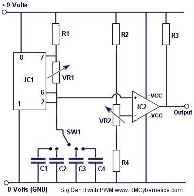
A DIY Square Wave Signal Generator with Pulse Width Modulation
This circuit is very simple and has a fantastic range of potential uses. The two potentiometers (variable resistors) allow the frequency and pulse width to be varied independently and without affecting each other like in the super simple signal generator.
By incorporating a rotary switch, the value of the timing capacitor (C1) can be adjusted. This allows the frequency to be adjusted over the full range that the 555 timer can support.
A separate chip (LM393) is used to control the pulse width so that it will not effect the frequency. The LM393 is a ‘Low Power Low Offset Voltage Dual Comparator’ The pot (VR2) is used as part of a voltage divider so that the voltage on the inverting input of the comparator can be smoothly varied. This voltage determines the pulse width of the final output signal.
Like this circuit? Check out our range of Pulse width modulation circuits.
| IC1 | LM555 |
| IC2 | LM393 |
| R1 | 10k |
| R2 | 10k |
| R3 | 2.2k |
| R4 | 10k |
| VR1 | 1M |
| VR2 | 10k |
| C1 | 47nF |
| C2 | 4.7nF |
| C3 | 470pF |
| C4 | 47pF |
| SW1 | 4 Pole Rotary |
Since the pulse width is relative to the input voltage on the this input, it is possible to use the circuit in conjunction with a multitude of robotic interface boards. This signal can be used to drive a H-Bridge or power transistor which is ideal for varying the speed of a DC motor. We have some circuits based on this idea on the Cyber Circuits page. We also have a simple DIY version of this device here
Potential Uses Might Include:
DC Motor Speed Control Control
Boosting or Variable Dimming for LED’s and Light Bulbs
Transformer or Ignition Coil Driver
This circuit was used in the Power Pulse Generator project as part of the Ignition Coil Driver


Thanks for the circuit. I built one long time ago for experimenting with things. But now been needing a PWM driver for an HIP4081-82 full bridge driver. I’ve been playing with this circuit until I got something working. I’m driving a decade counter off pin 3 of the 555, set for a 2 step count. Feeding both of those into two AND gates, then take the PWM output from the comperator and feed into the other sides of the 2 AND gates, And there I got it. Two variable pulse width signals running 180 deg off from each other. Running the decade counter off the comparator didn’t work. It unstabilised the counter and got fluttering LED test lights. The bridge driver data sheet circuit shows an inverter gate to flip a single sq wave input opposite, to drive the second half of the bridge, but that would only work with full duty cycle. Start reducing the duty cycle on the input square wave and the inverse side increases it’s duty cycle the opposite way correspondingly throwing the balance off.
Hi,
Great circuit!
I’d like to use that idea of using the second half of the comparator for a second output, using a dual-ganged potentiometer to adjust pulse-width of the two channels.
But I’d like the second output to have half of the pulse-width of the first … any ideas?
Thank you!
managed to get circuit working.
i was using a 2.2 ohm pull up on the 339 instead of a 2.2k.
circuit works a charm
Hi all. I have made this circuit and i am running it on 12v.
i get a pulsed dc testing pin3 with oscilloscope.
changing the 1m pot does change the frequency.
i am using a 100nf capacitor
the problem is i dont seem to be getting a sawtooth wave on the pins of 2 and 6.
its a constant 3.5v.
thanks
It is proportional to the position of the duty control. When at zero, duty is 0%. When at 10k, duty is 100%
Hi!! how do you determinate the duty cicle? if is of 60% 70%…100%? do you use formula?
The LM393 compares the voltage of the charging/discharging capacitor (sawtooth waveform) to the DC value set by the potentiometer. If you draw the sawtooth shape and then intersect it with a line representing the DC value, you can see how a low DC voltage will intersect at two distant points while a higer DC value will intersect at two points very close together. The distance between the intersecting points is output by the comparator as the pulse width.
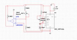
Hi I simulated this circuit with others values ​​of components in the 555 because i need the frequency of 1Hz-100Hz and I use the formulation of 555 astable That Is: 1.47 / ((R1 + 2R2) * C). right? I have this in the output frequency of 555 but..I don’t Understand the function of LM393. I simulate in the multisim and works good Because don’t change the frequency. Can you Explain to me how the LM393 does it work? and Why do you connect the input (+) With The 6 and 2 of the 555?
The PWM-OCXi v2 works like a switch. For example; If you supply it with 20V, it will pulse your coil with 20V. The max limit of 30V refers to the supply to the circuit. It needs a 12V to 30V supply for it to operate, but you can then use it to switch power from a seperate power supply if you want to use a voltage outside that range.
I don’t know where else to ask this question.
I want to purchase the Power Pulse Modulator – PWM-OCXi v2 to power an ABHA vortex coil for healing purposes. I am confused about whether I need an external power supply for output to the coil above the input voltages that the OCXi v2 accepts. In other words will it put out 30v at up 9 amps to a coil by itself? If I need an external supply of some sort do you sell those?
That voltage should be fine. You can also use the output for driving several injector drivers together.
hi, im wanting to use this circuit to drive a LM1949 injector driver. i want to drive the circuit with 12-14volts?(instead of 9) and i assume the output to the lm1949 will be a similiar voltage as the circuit input? do you see any reason why i couldnt use this as above? would i have to use one circuit for every lm1949? or will this drive more than one at a time? also im wanting to add another 555 before the circuit to preset the on time of the circuit. if i use a circuit for every lm1949(i want to use 4) do i need a timer for every one as well?
much appreciated
cory
Any type will work. Larger capacitance will cause a lower frequency.
What type of capacitor are you using in this diagram? And does it matter that I am using higher capacitance rated in the micro farads in this project?
Good night! Congratulations on the site! I’m intending to use this circuit in a dielectric to produce ozone! I already have a similar circuit, but with an astable comum.Penso with PWM that I have more spark output and therefore higher production of ozone in the dielectric! I wonder if you can tell me until a frequency coil automotive (bosch) stand before exploding, and can explode if over-frequency or not! Also like to know what is the maximum stress that can bring this same coil before it starts blowing! I’m waiting and thank you very much any information! Big hug from Brazil!
I’m not sure what you are referring to. Can you quote it please.
great job .. i was reading your manual and in it you said this circuit can be used with a capacitor attached VCO between the inputs of a ignition coil. can you explain how it works? and do I need a third circuit to do this?
No, this circuit only works upto 15V and is not suitable for driving coils. You need something more pwowerful and with some protection against voltage spikes.
We sell such circuits, our PWM-OCX range.
Is this the most suitable circuit if the input ‘source’ voltage/current is ranging and potentially minimal to 100’s of volts? I want to drive (oscillate) a secondary coil but seem to be burning out my other circuits and transistors.
Also…do you sell these already assembled?
Thanks!!
Load goes between output and GND.
please could you tell me how do you connect this circuit to a load, i see the output wire coming from the LM393 IC, what about the two end wires?
WOW!! this is just what i need.
thank you for a really GREAT site and all the help you give us electronics newbies.
again thank you, packrat
Yes, it should work. Just wire the second comparator as the first one and link the inputs together.
is it possible to use both halves of the comparator lm393 with the single 555?
i would like to have a circuit that has one output at 10% duty cycle and the other at 75% duty cycle, but switching at the same time.
using the 555 to feed both sides of the lm393 would be the easy way to do this. but will it work?
thank you for all your help!! packrat
It can drive some LED’s diectly. If you find the datasheet for it, you can see exactly what its ratings are.
What is the current output of the LM393? Is it suitable on its own to drive a couple small LEDs or should I just use the output to switch a small transistor? I’m talking 50-75ma at most.
Thanks
Ahh, That’s it, it was working except I was using a blown MOSFET 😛
Gibs,
This is due to capacitance in the components. This is especially apparent when driving a MOSFET becasue the gate pin is basically a capacitor.
To overcome this you need to drive the gate at a higher voltage using a transformer or a special MOSFET driver chip.
Shannon,
That is beyond the scope of this article. You would need to use a microcontroler for the frequency counter.
Generator,
That is for adjusting the frequency output.
Hey, I built this circuit and the variable resistor on pin 6 and 7 doesn’t seem to do anything, What it is supposed to do?
How can i make this circuit into a function generator with a frequency counter ranging from 100Hz-999Hz with a LED readout?
Hi RM,
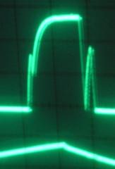
I’ve built this circuit and it works as you stipulate. I observed that the higher I bring the frequency, rounder is the attack of the square wave output. Is there a way we can keep the full squareness of the wave at all frequencies? I’ve got to drive a 200 A mosfet.
Thanks, great site!
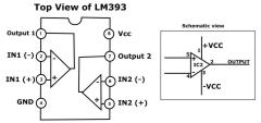
The info is already on this page. The plus and minus indicate the non-inverting and inverting inputs. You should google for basic information like this or read the component datasheet.
hello friends,
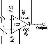
i’m confuse for the IC2 part..where to connect it to another part? where is the pin number for the IC2 ? unlike the IC1 part
on IC2[LM393] what is the meaning of + – sign ?
the IC2 part is LM393 which have 8 pins..
very thank’s for anyhelp
thank you sir RM, i have now a coil driver… with a spark gap of 2 inch.. thanks a lot
Yes but electrolyitics are generally a larger value and would therfore make your circuit osccillate at lower frequencies.
Can i use Electrolitic capacitor replace for C1 c2 c3 c4? to drive a ignition coil?
Of course! The title of the article is “A DIY SQUARE WAVE Signal Generator with Pulse Width Modulation”
can I produce square wave with this generator?
Yes you would connect like you suggest, The symbol used just represents a varying resistance. The set resistor could be connected either side of the pot as it would make no difference.
hi, another dumb question . when using a resistor and pot as you suggested to limit the frequency, how would it be wired into the circuit? the resistor before the pot or after? in the schematic at the top of the page shouldn’t the connection from the pot to pin6 of the 555 go to the pin 2(wiper) of the pot? i’m just an old guy trying to make sense of electronics.
thank you again for all your help and patience.
wow!!!!!!!! this is the explaination i have been looking for! all the so called experts on other sites make things out to be so “you don’t know the ‘handshake’ so we can’t tell you”
thank you for giving me the information i have been looking for!!!!!
packrat
You would need to use a 1nF timing capacitor and then limit the range of resistance you can vary by adding a resistor in series with the pot. You would have to detirmine the values for those yourself.
e.g. Use a 1M pot, set the frequency to 40kHz then remove the pot and measure its resistance. Do the same at 2kHz. The first value you get would be the value for a resistor that you would place in series with a pot rated for the second value you got.
again thank you for helping a new to electronics old guy! i really only need between 2K to 40K frequency. is there a way to get that? thanks again for all your great help in this matter!!
The best way is to add a lower value pot in series with the 1M pot. You can then use this extra pot to fine tune the frequency selected by the main pot. The lower the value, the finer the tuning will be. e.g. Adding a 10k pot in series with the 1M pot will give you a dial which is 100 times more precise because the value is 100 times smaller.
wow! THANK YOU!!! i was figuring them with a online 555 calculator, and thought i was doing something wrong. the range of difference on each capacitor just seemed too large.
is ther a way to make the frequency vary over a smaller amount? maybe change the value for VR1?
thank you again for your help. packrat
220nF – 3Hz to 600Hz
47nF – 14Hz to 2.5kHz
10nF – 71Hz to 10kHz
1nF – 710Hz to 87kHz
470pF – 1.5kHz to 170kHz (after this point the pulse shape is significantly rounded)
100pF – 6kHz to 263kHz
47pF – 10kHz to 870kHz
Logarithmic pot is best for frequency
hi, would you please post the frequency ranges for each of the timing capacitors.
also which type pot(VR1) would give a more gradual adjustment for the frequency, audio or linear taper?
thank you for a great site and great circuits! packrat
It will work fine with no changes
reference circuit -A DIY Square Wave Signal Generator with Pulse Width Modulation using (LM393)
can you use a tlc555 IC instead of 555
If so what component changes are needed
thank you
Thanks for the info. Makes sense to me now.
Well if your duty is 10% then the pulse duration depends upon the frequency. e.g. 1hz, 10% = 0.1 seconds
I was just wondering how short the pulses can be using this circuit. Like let’s say I have a 10% duty cycle, how many microseconds would the pulse be. Is there anyway to tell?
what type of circuit may i use because i don’t want to use the circuit that includes (DSP,MCU)plz, i’m only left with this part to complete my project.
No you would need a differnt circut for a three phase output.
I’m designing three phase induction motor speed controller this circuit includes 3 gate drives IR2111 that controlls the turning on and off of the Mosfets in the inverter.These gate drives are are fed from three phase PWM that icludes software program that i dont know, i’m wondering whether i can modify that with your square wave signal genarator with PWM ? and then create three of these these circuits.thanks
thank you for your prompt reply! this question had been asked before and answered two ways – run on 5vdc and use a 7805 to regulate the out-put didn’t know which was right! I’m going to incorporate it in a circuit already at 5vdc and didn’t really want to add another power supply!
thank you again for the reply and a GREAT site, cary
Both IC’s should work from a 5V supply and you should not need to alter any resistor values.
hi, this circuit is just what i’ve been looking for!
a couple of questions though, i need the output signal to be 5vdc,or ttl level, if i power the circuit with 5vdc as vcc will i need to change any of the resistor values? if so what are the changes?
thank you in advance, cary
No, You could damage your PC. You would need to find out the specifications of the line in port and then make sure your circuits output is adjusted to match.
to test the wave generated would it be ok to plug this into the line in on a computer…
Deutsch,
I can only assume you mad a mistake in your wiring or that you have a faulty component.
Ed Lipton,
You can connect this direct to a 13.5V supply. The voltage limit is simply determined by the ratings of the two IC’s. You can Google for the datasheet to get the max voltage of each.
Hey Rm, Great site! Don’t understand it all,,,,but great site and it drawwwws me in. Am just learning something new “electronic’s”@ 53 years now. Can you PLEASE,,,,,, tell me, how I could hook this up to 12 volt DC “actually 13.5, charging”? I don’t know that I would but seems that all these projects I find are based on low voltage DC. I am trying too do some thing’s to increase M.P.G.’s and am looking at PWM’s and Hydrogen ect, ect. So what is the easiest way to bring down voltage and have everything work?
Hi, I built this circuit and everything seems to be fine. Frequency changes correctly and the pulse width seems to change correctly also, however, I am only getting around half voltage(4.5V) on the output. Does anyone have any ideas why that might be?
12V will work fine.
If you want to switch large currents you need to use a large transistor on its output like in this circuit
If you hook this to a 12v supply instead of 9v, will it work as expected or fry it?
If it will fry it, which components would need to be replaced to make it work with 12v? Likewise, which could be replaced to allow it to operate up to 20 or 30 amps?
Thanks!
The 555 output is a square wave. It would be usless to put the squarewave into the 393. The signal is taken from the timing capacitor which is triangle wave. The 393 compares the voltage of this wave to the voltage from the 10k pot to determine if the outut should go high or low.
Hi, I haven’t build this yet. As per my memory.. the O/P is the third pin (555 IC), but in here it left unconnected. Can you explain little bit?
Thanks. My switch was on the wrong side (on GND instead as above).
1.Another thing, for adjusting min and max level of duty cycle on needs to adjust 10K resistors on 393 input… a little inconvenient. I have connected upper end of 10K variable resistor to the pin 5 (threshold), which properly selects upper voltage level (about 2/3 Ucc) of comparator or min. duty cycle. Max. duty cycle (min voltage level aout 1/3 Ucc) still manually adjusted.
Any comment on that?
2. I found LOG variable resistors for freq. more linearly adjustable, especially for high freq.
Maybe some interference. Try adding some capacitors over the power supply terminals to suppress noise.
Nice circuit & clever design. Thank you.
However a problem: In tuning the circuit I have found out that the frequency is not constant but is is varying, especially at low freq, i.e. at 20 Hz up to 10%. Already output freq. from 555 in not constant. All measured with DDM.
Any clue what’s happening?
You can use this online 555 calculator here
firstly, awesome awesome website. very knowledgeable info. i would like to know how to calculate the 4 different capacitor values (C1 to C4). i am currently designing a magnetic arc controller and i need a square wave generator with PWM connection to a mosfet driver leading to 2 different mosfets switching low and high. i basically need to control the inductive coil for position, frequency mark space ratio and amplitude. thank you soo much for all this info.
yey, it worked! thanks a lot! 😀
bravo!
Is this a negative offset circuit being the pulsating output is negative current?
If so would reversing the polarity on the battery cause the output to be pulsating positive current?(positive offset)?
Thanks
Where do I get a Rotary Switch like the one in the picture, and what are the specs of the rotary switch?
RM,
Circuit is same except R3 is 2K Vs 2.2K. It is on bread-board right now so I can play with it. I will try different components and report back if no ideas. Thanks.
Ward
The low frequency should not be a problem. The circuit on this page will work from DC to hundreds of kHz.
Is your circuit somehow different such as a series capacitor on the 193’s input?
RM please help me understand why the LM393 (193) switches badly when saw tooth wave in from 555 is a slower frequency than say 65KHz? It only happens when input slope is too shallow. I would like to get down to 30KHz and still get clean PWM output.
If I try 100K R2, R4, and VR2 the effect is even worse. Any advice? The input saw tooth from 555 is clean. I zoomed in to limit file size. Thanks in advance.
Ward
This is a signal generator only. it will not drive coils directly.
Look at the ignition coil driver page for a circuit to drive coils.
i have already built a 555 timer circuit using a MOV and ablocking diode in series with the coil on the + input the – input is from an audio amplifying transistor it was working seemingly well although te hv was some how getting to the 555 it wasnt heating up neither was the transistor,but it is not working anymore… con you tell me what went wrong
No. This is a signal generator only. It will not even power an ignition coil.
if you used this to power an ignition coil, could it power a tesla coil this size?
I’m not sure about the maplin kit as I don’t have a schematic or any parameters for it.
Yes there needs to be a path to ground from the gate pin because it is effectively a capacitor and it needs to discharge to switch off the MOSFET. The 393 will do this to a limited extent, but it is common to just place a resistor between the gate and GND to drain off any remaining charge on the gate.
Excellent site you’ve got here!
How can I use a 555 noise maker kit from Maplin to drive an IRF740. The reason is to isolate the 555 circuit from the coil switching mosfet (and as a kit it’s easy to build!).
I admit I am struggling with some fundamentals here but I assume the gate has to be grounded after it is pulsed in order to shut off the IRF740. How could this be done? I guess thats what the LM393 does but can I do it without?
Many thanks
Thank you very much, for your quick reply!!
Yes it should run from 5V. You would just need a small resistor between output and your optocoupler to limit the current.
Hi! I havent built this yet, becouse I have some questions. Is it possible to use it with 5V DC? Becouse I need TTL signals to drive an OEM laser device. And i also would like to use an optocoupler, at the output, ill have to use a resitor there do I? I mean a resitor which makes te good DC depending on the optcoupler(I decided to use 4N25)And after that i should use two Shmitt triggers?(becous it inverts). Id be really happy if you could help me, I need it for testing at our Lab. Thanks. Pumee from Hungary.
u da man, I need what Stan Meyer made, 555 with frequency and width pots thanks runs off 12v dc 5 amp
These are the ‘power rails’ The top line is connected to +ve, the bottom line is -ve. It does not matter which end.
what does the end above R3 and the end way down at the bottom connect to in this circuit?
That is totally up to you. Decide how much current and voltage you need to switch then look in a cataloge/shop for devices that will handle your requirements.
Thanks RM for the info. Any idea which low power/smaller MOSFET I could use. Cheers.
This pwm circuit is almost identical to this except it drives a big transistor for switching larger loads. You can use a different MOSFET or smaller transistor if the IRF740 is overkill.
To make it switch a different voltage you would disconnect the load from V+, connect V+ to the input of your regulator, then connect the output of your regulator to the loads +ve termial.
Great Website. I have built this circuit and it works brilliantly. I use a 9V supply and I have notice the output voltage is between 8 and 9V, is it possible to bring the output voltage down to about 4.5V – 5V (oscilloscope reading) without effecting the PWM. I do have some success in doing this with a 78L05 Regulator on the output, which gives about 4.2V. I would prefer a better way as I don’t think this is quite right. Thanks Mark.
The power pulse controller or a PWM-OC10A would be better.
Can you get back with me on this. I am wondering if I can use this simple circuit to power a water splitting device whereas water is broken down into hydrogen and oxygen.
Get back with me at: 65t@commcast.net
Thanks, Tom
Yes you can run from any voltage within the component manufacturers specified tolerances.
lol! That’s a pretty interesting result. Part of the circuit must be coincidentally tuned to match the broadcast frequency of those Spanish people!
Very interesting thing with this circuit. If I touch or touch any terminal of 10k pot, while headphones are hooked up, I hear people speaking in spanish. I’m not joking. This thing is a radio or something.
The performance (the frequency and stuff) is not affected by the supply voltage, right? I can run this off of 12 volts, correct?
VR1 represents a variable resistance. If you use a POT you would use an outer pin and the middle pin. The other pin would remain unconnected.
LM339 should work ok.
could you please tell me where the wiper on VR1 is suppose to go. it doesn’t look connected, also can I use an lm339, can’t find any 339’s, what I’de like to do is have seperate inputs and outputs so I can overlap different frequencies if that makes since.
P.S. Love the site!
The output should go almost as high as the supply voltage (9V in this case). A 741 is not suitable for a direct replacement. This is because the 741 is designed for a dual supply voltage (+v, -v, and GND). The 393 is used here because it will operate from a single supply and is able to swing its output almost fully between the rails.
Can you tell me how high is the voltage and current from output? Can I use OPAmp 741 instead LM393 ?
Many thanks!!!
Yes. It will go from 0 Hz to about 125 kHz. This circuit will also provide that range of frequencies.
hi i nead somthing that i can control the frequancy betwen 10khz and 30khz will this do that
Thanks for the advice, ill stick to the original circuit. Once again, thanks for the great website, and for dealing with all us electronics newbies 🙂
Yes it will effect the performance. The LED will provide a path for current to flow between the capacitor terminals. It could prevent the capacitor from charging and discharging correctly which is essential for oscillation to occur.
Hey everyone,
First off, great website. Second, im in the process of building this now, and i just put in LEDs between the dial and each capacitor. Will this have any negative effect on my circuit? Its really just for aesthetics, so when you turn the dial, the LED assigned to that certain capacitor lights up.
You can use any method you like for adjusting the timing capacitance.
if you had a lower copasitor and then instead of the rotary you could use a dip and then you would be able to go through the entire frequency range. i think this is right but tell me if i am right.
No. This circuit will only work at low frequencies (i.e. audio frequencies). It will not work for RF.
before i go and try{?} building this circuit (or buying a complete one from you) i have a question on frequency: is it possible to get into the M or G frequencies with this device? judging from the posts i see here it does not appear so….
thank you
You only need to use pins 1 2 3 4 and 8. See the post by Santa dated Monday, 25th September 2006 7:27am for the pinout.
Looking at the image I posted. Which pins should I connect to 1, 2, 3, 4 and 5 on the schematics view. I have looked through the data sheets online, but I still don’t know which is which? Thank you BTW 😀
Not forgotten. There is no need to connect pin 4 for this circuit to oscillate
Hi there. I’m planning to build your power pulse controller to run a dual ignition coil HV supply for an electric fence. There seems to be a problem though, you have forgotten to connect pin 4 of the 555 to Vcc in order for it to operate in Astable mode. I’ve simulated the circuit on Multisim 9 and it works very nicely. Thanx.
Made the Tesla coil tester – but even by lowering C3 to 0.1 nF I get to a ceiling of about 500kHz!
Added a potentiometer in // to R1. At combined values of 190 ohm I get about 340 kHz signal – then the signal just vanishes from the scope screen.
Reducing the value of R1 may help. Try swapping it for a variable resistor, or just add one in parralel to it.
You could also try the Tesla Coil Tuner circuit. This goes up to around 450kHz.
Hello… Am using the circuit as a source to find the resonance frequency of primary and secondary of my Tesla Coil. At the 47pF setting (and also without any capacitor – must be parasitic capacitance) I get about 200kHz. Ideally I would need a range around 600kHz (calculated resonance frequency of my primary). Any ideas of how to modify your circuit to get that? A smaller capacitor (e.g. 4.7 pF at C4) still gives around 200kHz. Many thanks
Is there a way to make is run around 600KHz? On the 47pF capacitor setting (or without a capacitor -parasitic capacitance I suspect, as you mention above-) I go up to 200KHz . I’d like to use it to find the resonance of primary and secondary of my tesla coil, which resonance is around 600KHz… any ideas of how to achieve this? Many thanks
Very strange indeed… the DMM manual says 1.0v rms minimum for the frequency counter, but from the scope I think I have 8v peak to peak – I use a 9v battery as source.
The frequency measurment of many DMM’s requires a reasonably high voltage input (>10V). Its interesting that it works with no ground reference. I just tried with a DMM I have with a frequency setting and the result is the same as you describe.
The scope will be the reliable reading, I guess your DMM isn’t meant to be used for frequency in this way.
Hi RM. I made the Pulse width modulator and it seems to work fine… but I can’t make sense of the frequency measurements I get. I did set the freq. at 1000 Hz (using a scope). When I check this with a DMM (red on output, black on ground of the pulse modulator), I get 20KHz. If I only have one lead (red/positive) on the “output” I get the right signal – why this?? Many thanks – Thomas
With VR1 set to 0 the frequency will be max.
VR2 can be set to 0 resistance at either end of its turns, but ot will always be 10k between 2 of its terminals. It’s wired as a potential divider. If you turn it so that there is 0 resistance between R4 and the inverting input, pulse width will be maximum.
What I meant was if the pots were set to zero resistance. When VR1 is set to zero resistance is that the highest or lowest frequency, and when VR2 is set to zero resistance is that the highest or lowest pulse width? And would the LED go in line with the output or from the output to ground?
Yes you can add an LED to the output. You can just about see it blinking at the very lowest frequencies 30Hz. At higher frequencies the brightness would vary proportional to the pulse width.
It depends which pins you use on your pots for the direction.
Is it possible to add an LED to this circuit that blinks at the same frequency as the output? Would you be able to see it blink or would it be too fast? Also, when VR1 is set to zero is that the highest or lowest frequency, and when VR2 is set to zero is that the highest or lowest pulse width? Thanks for your help!
The effect would be just as you described. It would only slightly alter the percieved sound. The pulse width function is important for using it with power control for motors, lights etc.
Thanks. So what effect should turning the pulse width Pot have on the sound?
Being given the wrong info makes it difficult too I guess :). Seems like yours is working fine. I used linear pots.
With the 47nF cap The low frequency end is 30Hz, You’ll need capacitors in the uF range to get really low frequencies.
The circuit will even oscilate without a capacitor if there is enough parasitic capacitance elsewhere. I measured 222kHz, but the signal was quite small and not square.
Wow thats some range. Perhaps my circuit isn’t working right then because even if I have VR1 (which should be the freq. right?) turned right down I get a fairly low freq. that sounds more like an outboard motor but I can’t turn it right down to zero. And changing VR2 (the pulse width)just sort of makes the signal sound either more distroted or less distorted, so I just leave it mid way. Did you use LOG or LIN pots for this circuit? Its hard to know if its working right without hearing a working example of the circuit eh?
C4 is probably overkill really. The range is about about 0Hz to 125kHz, but the signal may start getting a little distorted at the top end.
You cant drive a large speaker with this circuit, but adding a transistor like in the Pulse controller will work.
I have built this crcuit last night….I listened to it through headphones and it seems to work. I don’t get much of a range when the rotary switch is set to C4 though – is that expected? Also, can you confirm what the freq. range of the circuit is (i.e 20hz to 20 Khz?) And will the circuit drive a 12inch loudspeaker? I want to try emulate those experiemnts in the video with the water/cornstarch mixture. Thank you.
No. Santas diagram is correct. It is just that the pinout diagram showing how it is arranged inside the DIL package shows the inverting input (-) above the non inverting one. Its just an easy thing to overlook because the symbol looks the same.
I see a contradiction here: RMCybernetics said “Note that the + and – inputs are inverted in the circuit diagram,” so shouldn’t pins 2 and 3 be reversed in Santa’s diagram???
R3 is used as a ‘pull-up’ resistor. It is neccesary to get a good output signal voltage relative to ground.
If it is not used the output signal will be too flat.
I’m kind-of new to electronics analysis, and am trying to build one of these to drive an ignition coil, and the circuit seems pretty simple, but I’m the type of person that won’t use something unless they understand how it works. As I said, most of this seems relatively simple, but I can’t figure out what the purpose of R3 is. If someone could give a quick explanation, I’d be very grateful. Thanks.
Nope its not neccesary. The signal going to the comparator is just from the charging and discharging capacitor.
I noticed in your design that there is no indication of where the output pin 3 would be connected, is this an oversight or is it because it’s not necessary. Thanks for all your support.
Wow, I really like this Circuit! Ive been fidgeting with Squarewave generators quite some time, but never came up with the idea of simply using a comparator for duty cycle adjustment virtually independent from the frequency. Ive packed this neat gadget in a little case with a 9V Battery and added some extra IC life savers by using optocuplers before the outputjacks. Comes in very handy when playing around with HV stuff like TC. Santas schematic seems correct to me, but in the worst case, there are two comps on the chip, so dont panic (exept u fry the supply section^^).
Re :-timothy Tuesday, 19th September 2006 1:13pm
I think what Timothy wanted was the connection details. Same as you did for the LM555..
See Example.
EXAMPLE ONLY.. CHECK FOR THE CORRECT CONECTION..
This is the pinout for the LM393. It contains 2 comparators, you just need to use one of them. Note that the + and – inputs are inverted in the circuit diagram.
You can download the datasheet for the LM393 here.
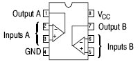
Can you tell me what pins on the LM393 chip correspond to the inputs for IC2 on the schematic?
Thanks
Thanks for this circuit! It works soooo much better than any 555 circuit I’ve tried. I’ve tried all sorts of 555 circuits for PWM, inlcuding one that used 2 555’s or a 556 chip.
This one wokred first time and provides exactly the frequency and duty cycle vairiability I needed for my motor speed controler.