 DIY Sensor Multiplexer
This device was created to allow more analogue sensors to be added to a homemade robot. It is simply a 8 port switcher for analogue or digital signals. The device is controlled by a PIC 12F675 microcontroler, and gives eight analogue outputs from one analogue input, and one digital input.
The K8000 computer interface board, used on the robot, is limited to four analogue inputs. A multiplexer was essential in order to capture more sensor data. The multiplexer can allow the computer to capture data from several sensors using a single analogue input on the K8000.
To do this it was necessary to create a device that could switch eight digital outputs one at a time and be controlled by 1 digital input from K8000. This is very similar to ‘running lights’ where several LED’s run in sequence and start again. To keep the multiplexer small it was decided that a PIC microcontroler would be used, as this would greatly reduce the number of required components. The chosen PIC was the 12F675 because of its small size (8 pin) and the low cost of the chip programmer. This PIC has only four digital outputs so these also needed to be multiplexed. The digital outputs when low can be used like a ground connection, allowing LEDs to be connected directly across two outputs as shown below.
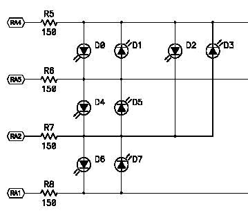
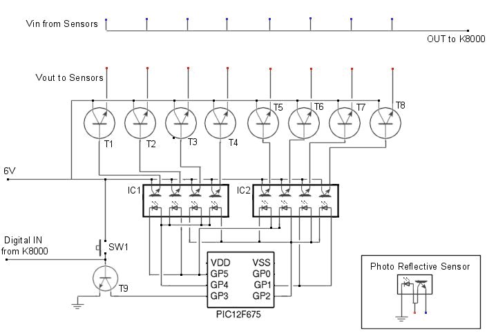
The diagram above shows how four outputs of a PIC can be used to control 8 LEDs. If these LEDs are inside an optoisolator then they can be used to trigger transistors, allowing a sensor to pass data to the computer. The diagram below is intended to show the connections of the sensor multiplexer. This diagram does not show some components such as resistors and capacitors, and is intended only as a guide.
To capture sensor data from the multiplexer a subroutine named ‘GetPlexer’ was created in the robots main code. This loop can read the value of the analogue input on the K8000, store it in an array, and then switch the digital output to the multiplexer on and then off again. This process will loop until all 8 sensors have been read.
| For plex = 1 to 8 ReadADChannel 2 Sen%(plex)= ad%(2) SetIOChannel 9 ClearIOChannel 9 Next plex |
‘ ‘Calls subroutine to get value of AD channel ‘Stores the value of AD channel in array position plex ‘Tells multiplexer to move to next sensor ‘Clears IO channel ready for next loop ‘ |
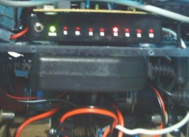
When power is connected the first sensor in the array will be active. It would be as if it were connected directly to the analogue input of the K8000. When the signal from the digital output of the K8000 goes from low to high the power to the first sensor is disconnected and the next sensor is activated. This process repeats until the last sensor is activated and then it starts again from the beginning. This was housed in a plastic box and jack sockets added to allow easy connection and removal of sensors.


