 A kirlian photo is a photograph of electrical corona produced around objects under the influence of high voltages.
There are two common methods for producing kirlian photos. One is a little tricky, but the other method is quite simple if you have access to a few basic bits of equipment. You can see how to make a high voltage power supply supply on the DIY ignition coil driver page and others. If you are less familiar with building electronic circuits you can use our power pulse modulator to drive a hv spark coil as a high voltage source. The electrode plate can be made yourself or the easiest way is to use ITO coated glass.
We have a selection of specially made transparent electrodes for use as Kirlian Photo Plates which work great in this project.
![]()
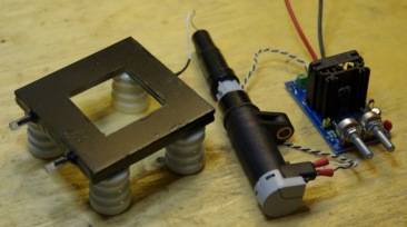
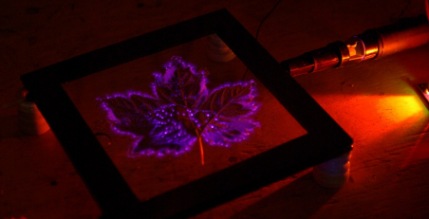
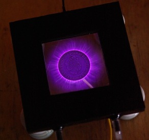
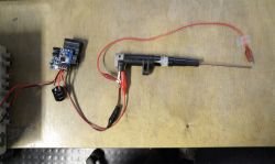
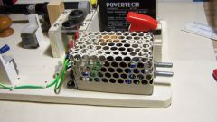
This method allows you to photograph or view electric field around object wit the naked eye. It works by creating a high voltage field between an object and a transparent electrode. The high voltage field causes ionisation of the air which is visible as a purple glow known as corona. The image above shows one of our Plasma Photo Plates resting on some high voltage insulators. You can use any insulator such as some plastic cups or glasses. Our electrode plates are provided with a filling syringe and caps so that it is easy to get started. Connected to the electrode plate is a high voltage spark coil which is being driven by our Power Pulse Modulator. The Power pulse modulator (PWM-OCXi) allows the high voltage coil to be driven with a variable frequency and power levels. This allows for different effects to be produced. At high frequencies, the plasma (or “aura”) tends to be softer and gives a smooth glow over most of the objects surface. At low frequencies the plasma tends to be longer and more jagged like lightning. It also tends to come mostly from the edges of the object rather than its surface.
Filling the Electrode Plates
First of all, the electrode plate must be filled with an electrically conductive solution. This is simply made by dissolving salt into ordinary tap water. You should add as much salt as will dissolve without making the water cloudy. Its is best to prepare the solution an hour before so that it has time to dissolve fully.
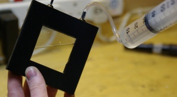
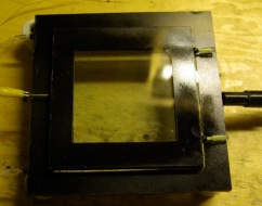
Connect the pipe to the end of the syringe provided and then draw some salt water into the syringe. (The amount needed will depend upon which size electrodes you have) Carefully put the other end of the pipe over one of the small plastic tubes on the edge of the electrode, tilt it as shown in the image and then slowly inject the solution into it. Make sure you go slowly to prevent leaks. Fill until a little solution comes out of the other plastic pipe, and then seal this with one of the caps. Remove the pipe and syringe and replace with the other cap. Wipe the electrode with a damp cloth and then make sure it is thoroughly dry and clean.
Attaching a sample
Take your sample such as a leaf or coin and tape it to the surface of the electrode as shown below.
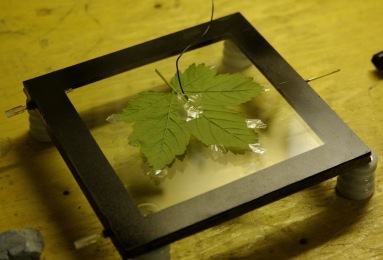
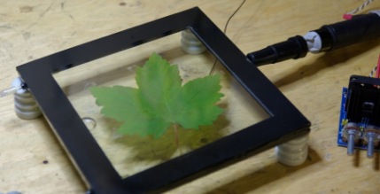
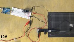
Tape a piece of wire to the back of the sample and connect the other end of this wire to ground. The ground connection should be the same as the ground or earth connection of your power supply. Turn the electrode over so that the sample sits underneath and place it on top of some insulators. You can use any non conductive object such as plastic cups or glasses. Connect the High voltage coil (or other HV power supply) to the metal connector on the electrode either directly as shown, or using a wire.
Connect all the other wires up so that it is ready to run. Familiarize your self with the layout as you will need to know where things are when you switch off the lights.
![]()
Taking the shots
Turn the lights off and give your self a moment for your eyes to adjust to the darkness. Turn on the power and tune it to give the best possible image.
You should only have the power on for several seconds at a time. If it is on too long the sample could be burned or the high voltage could etch marks into the glass. Also if used at high power, the PWM-OCXI and coil will get hot so they will need to be allowed to cool. We recommend adding a push switch so that you just hold your finger on it to activate the device while taking a photo. You will need a camera with a good lens or high ISO setting so that it can take good pictures in the dark. Using different settings such as shutter time will allow you to get different quality photos.
![]()
You can also try an alternative setup using two or more electrode plates together as shown below. This allows you to add samples without having to stick them down or attach wires to them. It also allows for a wider range of effects.
Using Two Electrodes
Here you can see one large plate at the bottom and a medium sized one on top. You can use any sized plates combined together but larger plate will need more power. The sample is placed between the two plates and the ground connection is made to the second plate. You can try having the grounded plate on top of the HV plate or visa-versa for different results.
Kirlian Photos using Photographic paper of Film
This alternative method uses photographic plates or paper which can be expensive and hard to find. It can also be tricky to do correctly. The advantage though is that you can sometimes get images with various colours showing. The sample such as a leaf is placed directly onto the photographic plate. When exposed to high voltage the corona will effect the photosensitive chemicals in the photographic plate in different ways depending upon the intensity of the discharge.

This diagram shows how the sample to be photographed is placed on top of the photosensitive paper with an insulated metal plate below. The lower plate is connected to a high voltage source of several kV. While the sample is usually grounded for brighter results.
Obviously all this setup must be kept in the dark as to avoid exposing the photo paper to light. The power is usually switched on for around 30 seconds to get a good enough image.
 If you don’t have photographic paper you could use the film from a polaroid camera. Polaroid cameras will eject a protective layer of card when you first insert a film. You can use this feature to develop your exposed film.
To make a kirlian photograph using polaroid film you should remove one film from the cartridge and expose your sample just as described above. After you have exposed the film, carefully place it back inside the film cartridge in the top position. Load the cartridge back into the polaroid camera and it will immediately eject the top film. When the film is ejected it passes between a pair of rollers which spread the developing chemicals over the image so that it is fixed and now safe to expose to the light.
Myths and Pseudoscience
 Many people claim that this sort of photo is showing the “life force” or “aura” of living things. This is something many pseudoscientists are using as so they can sell you these sorts of cameras for thousands of dollars. This page should hopefully show you how simple they actually are and that it is just simple corona and ionisation effects that are being observed.
There are also claims of a “Phantom Leaf” experiment where a kirlian photo of a leaf with a piece cut away showed an image of the full leaf. Proponents of this idea claim that this “proves” that the “Life Force” lingers on after the original piece of leaf is removed.
The only legitimate reasons for any phantom images would be caused by water or etching on the surface of the glass plates of the equipment. Any claims of anything else are totally unfounded and such people should not be taken seriously. If you try moving the cut leaf to a different camera, or use new clean glass plates then no “phantom” effect is observed.
You can even take kirlian images of things like your finger tips or whole palm. There are people who claim that you can diagnose illness from the shape of the images produced. This is really outlandish any many people are taken in by these scammers. There are charts that even relate each finger tip image to a certain part of the body or emotional states. These claims are just pure fantasy, and are another method used to make money selling expensive cameras.
Some of these sites often use scientific terminology in all sorts of inaccurate ways and even list quotes of support from people who are apparently Doctors or experts in something. The fact is that there is no legitimate reproducible experiment that gives evidence to support any such claims.
Example Kirlian Photos

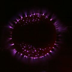
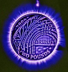
This kirlian photo shows a £2 coin between two of the electrode plates. The surrounding dots are caused by tiny amounts dust and dirt on the glass surface.
>
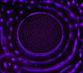
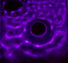
This kirlian photo shows a close view of the same coin and with a higher frequency supply. You can see rings or waves around the coin.

Another shot of the waves around the coin

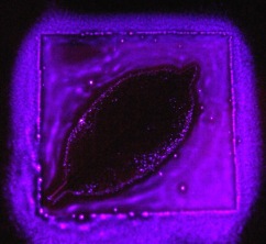
This is a photo taken when no sample is placed between the plates. All the little dots are probably dust although we had tried to clean the surface thoroughly.
Some of these dots would move around the electrodes due to electrostatic effects.

Same image with longer exposure time on camera.

This is a photo of the leaf shown in the instructions above
By adjusting the frequency while watching it, you can see the glowing corona move around different parts of the leaf.
Another leaf image at high frequency.

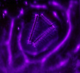
Three Neodymium Magnets between the electrode plates.
A single Neodymium magnet
A bunch of little magnets. Notice the rings or waves again
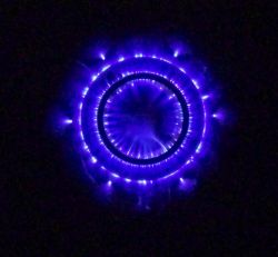
The £2 coin at low frequency under a single electrode.

More Photos
You can see more Kirlian photos and high voltage plasmas on the Plasma Page


Hi, i am about to build my kirlian device with your PWM OCXi v2.2 i and HV SC20K hv spark coil but i was wondering if it is suitable and safe to put our finger on it? I read that it should be less than 1 milliamp to keep it safe?
I read your comment on this question 27/05/2009 but i don’t know if this is still the case using your uptodate PWM OCXi v2.2
We shouldn’t ground ourselves in this case..
Not touch anything else around
Ground on a plastic sheet
Stay with the left hand in the pocket
To start with the power supply specs of the PWM OCXi v2.2 for kirlian photography:
– what 12 V amperage battery do you advise for Kirlian with or without body contact?
– Or should this be 12 v 7 amp and i should adjust the current limit adjustment on the circuit? How do i know (or where should i measure with my multimeter) the value of the amperage of the output to be sure it’s safe for body contact?
Thanks very much for the advice,
There’s no way I could suggest any particular method or test you could do that makes it safe for body contact unfortunately. Such a thing is done at your own risk. However I can offer some of my experiences with doing this.
Using the OCXi and a spark coil is running at frequency that you will definitely feel. At the power level needed for an image, you will at the very least feel a prickling sensation on a fingertip.
When taking my fingertip photo, I would start on a very low setting that would be drawing maybe <1A from my PSU. Slowly coming close to the glass with a fingertip, I could feel the intensity and look for any corona. It was then a matter of repeating this with a slightly higher setting each time until I got the desired result. Remember that there is not only risk of shock, but the corona can burn you too.
While not essential, it is better to keep it as it prevents stray fields causing problems.
new PWM arrived, looks good, as the HV plate is no longer mounted on the same board as the PWM but about a foot away, can I dispense with the Faraday cage, or is it good practice to leave it in place?
It is hard to say without testing it directly.
I am only getting about 2v across the coil connections, does this suggest that it is the MOSFET?
Incidentally, I showed the device to a chemistry teacher, she suggested heating the water when dissolving the salt to super-saturate. So I microwaved it and got a much stronger solution, I think that’s why those samples created such energetic effects. Thanks for you help
An IRGB4061DPBF was used in older models.
just realised it must be the transistor right in the middle with the big heat-sink
can I replace it and could you supply one and how much!
cheers
I did consider getting a new PWM, but cost is a bit prohibitive especially as it will only be used a few times to convince non-believers how we made the pics! Could I just replace the MOSFET?
I have no idea where in the circuit this is,, sorry to be such a pain. I have attached another of the pics taken tonight, this is a 3/4" brass back-nut from a tank connector.
Hi Colin, I could only think it would be the MOSFET as there is not much else on the circuit. You might want to try one of our new PWM-OCXi v2 units as they are significantly improved over the older versions. They have avtive transient protection and use a modern IGBT with drive circuit so you will get better performance and reliabliity all round.
hi Richard, long time no see. I built a Kirlian device back in 2009 and it helped my niece Lorraine get her degree. Now we have decided to bring it to life again. Built a new plate charged the battery and success, some great pics, Then I decided to try a hand pic, got a shock even though everything was earthed like normal, but then could not get the device to work, changed both chips several times. All connections are sound, battery is fully charged and all the lights flash etc as before. Just not getting a hv supply. any idea what else I may have fried? Pic attached of a compression nut so you can see how well it worked.

The coil should be pulling at least a few amps. Test the resistance between the coils input terminals. It should be very small. If the resistance is correct, I can only assume that there is some problem with your PSU or connections.
There is no spark at all.
I tried the low freq (20Hz), low duty with 12V and the PSU shows me a current of 0,05 amps. But still no spark.
Do you get no spark at alll. Even just a mm? How much current does your PSU say is flowing when you are running it? Try running at a very low frequency like 20Hz with a low duty as this will give longer sparks.
Hi there,
I am still trying to built a kirlian photo device. In my last post I mentioned how I tried to do it with an Arduino, but as you recommended I bought a PWM-OCmi. I hear the coil working but I still get no spark. Still using a 12V power supply.
I attached a photo.
Hope you can help.
Thank you,
Lukas
For the ignition coil to work, it needs a nice square pulse. Unless you are using a logic level MOSFET for your transistor, I would think that the Arduino is not fully switching the transistor. The arduino output will be at most 5V, but most MOSFETs or IGBTs need at least 10V to switch properly. It could also be that your 12V supply can not deliver enough current. It must be rated for at least 3A to work properly. Adding some large capacitors to the supply rails would also help.
You are also risking damaging your Arduino, and the connected computer when doing this. Ignition coils will make a lot of feedback which can cause problems for low voltage circuits. I recently used an Arduino to control one of these coils. To do this, I powered the coil via one of our PWM-OCmi circuits, then connected the Arduino output to the INT (interrupter) of the PWM. Doing this lets the OCmi deal with most of the transients so that the arduino can keep working.
I just bought the HV ignition coil you offer in order to build a kirlian photo device. As a PWM I use an arduino to regulate frequencies between 50 and 2000Hz and a 12V power supply. Unfortunately it does not work as expected. I do not even get a spark with the coil. It just makes a really calm buzz-noise when I increase the frequency. Although the circuit seems to work proper. I test it with a speaker instead of the coil. But I am unsure if the coil is working correct. Is there any possibility to test the ignition coil?
The new model will not need the 440CA or heatsink. It is excpected March/April. You can also use the PWM-OCmi for low power or short durations.
Hi, to begin, I’ve made myself a shopping list below; does it seem adequate?
Ignition coil, PWM OCXI, TVS diodes 1.5KE440CA, hv rated Insulated wire, Copper foil tape for edges of ITO glass and for HV connection, Faraday cage for PWM, Heat sink for PWM, single pole momentary contact, push to make switch (switch on +ive from battery),
mount board.
PS: The PWM OCXI has been discontinued from this site; is there any indication of when the new model will be released?
thanks much to all contributions on this page so far!
Very intrigued w/ ITO Kirlian plates, but your site
info is a bit sparse, even tho you have a sponsor.
Could you "spec" a proper ITO plate w/ particular
emphasis om Ohms/sq., and the "why" thereof? I’m interested in the range of 5"x7" or bigger.
For what it’s worth, drag racing ignition coils are available with 60 kVDC outputs. In your push-pull configuration, these would develop 120 kVDC, which seems ample. If anyone is interested in this kind of "wretched excess," I’ll provide sources. Expect less than L75 for a pair.
Many thanks.
The tube was 2mm OD to match the spacing between the glass. ID was about 1.5mm. Ordinary glass was used in both examples. With ITO glass, no liquid is needed.
Hi there, I am trying to make a Kirlian divice for my school project in the Netherlands. I have two questions about message #2122: Whats the diameter of the tube, inside and outside? Is conductive glass used(silver or tin oxide coated)? About message #3853 Is here plain glass used or is it also conductive? Thanking you in advance. Michael
Copper wire would be ok. Something this large though may need a lot of power or givie a fainter image for the same amount of power. You can use two electrodes together by connecting one to GND, and the other to HV, you can then leave the sample unconnected and just placed between the plates.
Hello! I am attempting to build a transparent electrode with little knowledge about circuitry and stuff. I’m making a rather large (18 x 24) electrode in order to photograph larger objects for a fine art photography series. larger copper sheets are expensive, especially considering I would be cutting the whole middle out to make a copper ring. Would bare copper wire work just as well? Also, I was intrigued by your mention of using 2 electrodes together to create different effects. Would I need to alter my power source/wiring? How would that work? Sorry for the very basic questions. I’m an artist, not a scientist lol.
You would want a “single pole, momentary contact, push to make switch” It should rated for 5A or more.
Alternately, if using one of our OCXi pulse modulators; you can replace the SIG jumper with connections to the switch. This way you can use a smaller switch if preferred.
Hi, I have received all the parts from you for my Kirlian device, but i notice you advise adding a push switch. When I went to purchase one I was told there was more than one type, could you tell me which is best for this project?
David, Yes, you can use either method
can you use TRANSPARENT CONDUCTIVE COATING plate for the electrode insted the salt soloution?
do you really need a electrode plate for ignition coil or you don’t need it, just the connection of the ignition coil connects to the salt solution filled plate directly
electrode / frame Transparent electrodes touch the big screen instead of using a mobile phone good results 38998199@qq.com
I just received this equipment for Kirlian photography. The results are great as expected!
However be careful! Corona (Kirlian) effect radiates ultraviolet light which is dangerous for a naked eye especially in a dark room! I captured about 10 photos for my digital camera, for each one I spent 5-10 seconds and my eyes got tired strongly. So I will use sun-glasses or watch DSLR camera display.
With Mobile Touchscreen Instead Plasma Photography Plate Effects ok
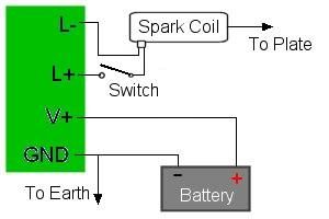
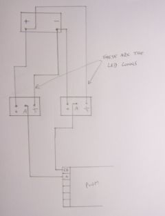
A few people have asked for a diagram showing the connections between the PWM-OC units, a spark coil, and the battery. So here it is.
Power cables should be thick enough for at least 3A.
If you use a wire to connect the HV output of the coil to the plate, keep it short and do not allow it to touch anything else.
Here is also a useful application note about transient protection.
Vasi,
Your diagram is correct.
Colin Cade,
For wiring the coils in parallel, just wire each every identical connector together.
Driving four coils at once may work, but I would prefer to test it before I commit to that. The DC current would be too high for them, but when pulsing, the current may be ok. I’ve none of those coils left, but will have more next week. I’m not sure if they will be identical as they will be from a different supplier. If you send me an email about it, I will be reminded to test it out for you when I have them. I think you will at least need to use a fuse so that it would be protected if the current gets too high.
Bigger plates will need more power, especially if the area that will be glowing is larger.
Switching the coils separately wont really work if the pulses are not timed together. If one is outputting but another is not, power will be drained away by the inactive coil. The PWM units can be connected as a master/slave so they pulse together.
A 4Ah SLA may be a bit pushed. I would recommend using a larger one. I would also recommend placing a large capacitor in parallel with the input to the PWM. The 10A switch is just about OK.
Yes it uses the same two IC’s.
The gas plate could be integrated or as a separate thing. If they are separate you would have more configuration options, but you would have two layers of glass when using both a liquid and gas plate.
The gas plate could be permanently sealed as the gasses are inert and it would need no electrodes. Try searching for a local BOC distributor, they have scientific and technical gasses.
If you are going for something as large as A4, the low pressure may cause it to implode with ordinary glass. It may be necessary to use toughened or extra thick glass. I can make one for you but there will be a minimum order for the gasses (20l) from my local supplier. If you wanted me to ship the remainder it would need to be by surface mail as most couriers wont ship pressurised canisters by air.
Hi Richard, after some thought, Lorraine and I have decided to go ahead with modifications to our original Kirlian device as per Lorraine’s query post no. 4051 and your suggestions in post no. 4053
We intend to use the original set-up in my post no. 3865 with the following mods.
Replace the PWM OC10A with a PWM OC30A.
Remove the 6 x 4 HV plate and utilise the space by installing additional HV-SC20K coils wired in parallel not sure what several would mean in this case, but four seems to be a good number. What do you think? Perhaps you could also point me towards a wiring diagram so I do not make a complete fist of it.
Build a new HV plate at least A4 size, I should be able to make it better this time with previous experience and mishaps how to do it, and with your comments from original project.
With the addition of your inspired suggestion of a low pressure gas filled plate.
Now the questions:
Would the OC30A power the coils successfully.
Is the A4 plate likely to need more power.
What do you think of switching supplies to each coil separately to vary the power output, or should the PWM do this better anyway
Would the existing SLA battery (4AH) and switchgear (rated 12V 10A and 24V 16A) handle the extra power, if not, what are your suggestions
Does the OC30A use the same IC’s (555 and 393) in case we fry some, as I have bought a strip of each as spares!
Now for the gas plate:
Should it be an additional stand-alone item or built as an integral part of the HV plate
i.e. a three layer glass construction with two chambers.
Argon and/or Neon
I know the salt filled plate would need to be emptied occasionally, but would the gas plate be permanently charged.
Will Google Argon and/or Neon suppliers, but would appreciate your input here.
And if my attempt to make a totally safe plate fails, although the addition of an additional barrier between subject and HV should be a bonus, could you quote us for manufacture of said plate?
Regarding operating times, I have managed to run the original device for over a minute with no problems
many thanks
Dear RMC,
I bought from you a pencil ignition coil PBTP-GF 20 (Sagem) and a PWM-OC10A for Kirlian Photos.
Question: Coil terminal (B+) is between Ls and Lp?
I don’t know if my assumption is correct. I want an electric scheme for ignition coil PBTP-GF 20, if is possible
It wont work so well with 3D objects. The electric field from the plate diminishes rapidly as the distance increases. The way to do 3D kirlian photography would be to have the object within some low pressure gas so that the glow can be produced more easily. Alternatively you can use very high at very high frequency like from a Tesla Coil
Thank you for this very informative page and clear instruction
1-How does is function with non flat objects such as a piece of stone or spherical objects?
2- Is it possible to get a photograph of the electromagnetic field of a crystal? to follow the changes caused by heat, external magnetic field, chemicals, etc?
Thank you in advance for a response
What you are doing will not work at all for a couple of reasons.
1. You cant possibly manually switch it fast enough with your hands.
2. Your PSU wont be able to supply enough current. You need something rated for at least 3A.
There’s everything you need to know on this website. Either the comments above, or see the ignition coil driver page
Sorry I forgot to add:
I’ve been toggling manually the switch on and off very fast to get a “constant” pulse.
Thanks,
Denise
Thanks for your response,
I got a small spark from the circuit does this mean it worked?? I don’t know if it’s strong enough though, cause all I did was placed the ground wire near the electrode plate to see it jump from the cable to the conductive mesh in between the plexi glass. I already ordered a tin oxide glass so that I don’t have to use the plexi and wire mesh, but my questions are: instead of buying the power pulse modulator can I use a 555 or 556 chip to create an Astable circuit? I need to build it by myself cause it’s for my thesis, and another question please, what kind of capacitors are you using?, I’ve been using 2x 3300uF in series but maybe that’s the reason why the spark is not strong.
ps: now it’s not being powered by 9V batteries, I am using a 12V wall converter as the input source.
Thanks for your time and help 🙂
Denise
The diagram you have shown will not work at all. You need to use a high frequency square pulses to drive the coil.
Our PWM Circuits will do exactly this.
You should also use real glass. Plexiglas (plastic) will be melted by the process which might only let you use your electrode once. We also have some glass electrodes for sale.
Hi, I am a master’s student working on my thesis that involves Kirlian photography. Thanks for all the info it’s been really helpful.
For the last weeks I’ve been working and building my device and today I started testing it but it’s not working. I can’t figure out which capacitors I need to use if my input is a 12V ac-dc wall adapter or 7 9v batteries in series. Apparently by measuring the voltage with a potentiometer my voltage is fine until I plug the ignition coil, this last one is draining all the juice and it’s not letting my capacitors fill up. Can you please help me with this issue?
Attached you can see the schematic I am following.My ignition coil is from an automobile store and it starts up with 12V.
For the transparent electrode I built a low res by making a sandwich between two transparent Plexiglas sheets and a wire mesh connected to the HV wire.
Thanks for your time I really appreciate it.
Cheers,
Denise
For photographing fingertips you have to come into contact with a high voltge device. Doing this with a home made device can’t really be considered safe. That’s my disclaimer, now I can try to give you some tips on how to reduce the dangers 🙂
There are two main dangers. The first and obvious one is electrocution. Using battery operated devices and ignition coils greatly limits the power output and therfore reduces the chances of a lethal shock even if something went wrong. Careful construction and making sure all HV parts are well insulated helps too. Having a larger plate reduces the change of you touching a HV wire or a spark jumping to you as your finger would be further away.
Making sure you are insulated from the earth helps to reduce the chance of curent flowing through your body.
Higher frequncies will give less sensation on the fingertips.
The second danger comes from the mere suprize of getting a shock and is much more likely to harm you than the shock itself. Just be aware of your setup and your surroundings.
To go up in power you could use a larger transformer or just connect several in parallel. You would also need a more powerful driver than the OC10A though. The PWM-OC30A would work well.
Other ways to get a brighter view would involve the use of low pressure gasses like Neon and Argon contained in a glass space between the subject and the HV electrode. The gasses would glow brightly as they would moe easily become ionized than the open air.
Following the work undertaken by Colin Cade building a Kirlian device (with your much-appreciated input & products), I’m tempted to go further into the experiments I did with it and wonder if you can advise on if/how the device can be re-built to a safe standard for taking fingertip corona field images.
Additionally, is it feasible to go ‘up a level’ with power etc too, to create stronger images, and what would this entail cost-wise and resource-wise please?
Thanks in advance and when my university fees are paid I’ll be sure to make a contribution 🙂
Nice work. For videos, upload to youtube and put the URL or the video in your message.
and this is the logo of my niece Lorraines website, made from copper wire letters, cooking foil flower and thin brass strip for the petals. fiddly to make, but well worth the effort. I have to add my thanks to Lorraines for the help and support you have given us.

this is a starfish made from common kitchen cooking foil, it does make a very energetic image. If you can host a quicktime video, i have a short movie shot with my still camera.

hi, back again with update, connecting the device to mains ground worked well, thanks. Palm and fingertip images, with the battery losing power it was ok, but a fully charged battery was a bit fierce causing us to pull away quickly. We dont advise it.

also been experimenting with different materials, this is a lump of iron pyrites (fools gold) attached to a fridge magnet, although its non conductive, it does make a good image
See the diagram on the plasma gun page. Connect as Spark coil 1.
to excuse me if this message is a doubled bloom. I am impatient… In your new page, to speak to you about l’ apparatus: HV SPARK COIL. How to connect a HV SC 20K on a PWM?? .GRAND THANK YOU.
Going to conduct our palm test this evening – thanks RMC and Colin for all your efforts, questions, answers etc. We will be posting images of the tests for sure!!
hello Thank you to provide me the connection a PWM and one VH-SC20K .salutations
Yes, any adjustments to the circuit should be made with the power off.
good point about the water, will amke up a batch and bottle it.
for the ground issue, I used a car jump lead and clamped one end on a radiator pipe, as i went to touch the other to the cage, a spark arced across which supports your theory about unbalanced ground. unfortunately it blew the 555 IC. Was this because I connected the leads while the circuits were live, and it wouldnt have happened if the power had been off?
I subsequently discovered while replacing the IC that the previous meltdown in post 3875 had fried the LM393.
It might be that the feedback from your coil is bringing the ground to a higher voltage. If you connect your ground to a larger ground source such as mains ground, or a metal tap or radiator, this should absorb that excess.
The salt water will react with the metal electrodes. If you use copper, or brass, or have solder exposed to it, they will slowly contaminate the water. The copper might make the water go green after some time.
hi again,,, I fitted some control knobs with pointers, and an ali mount with dials on the device (grounded). While operating the device last night I was getting a tingling off the controls, or maybe off the grounded mount or Faraday cage? Is this normal, I was trying to take pics of my fingertips, and the tingle was severe enough for me to pull my hand away from the controls. I was nowhere near the HV part of the device.
Could it have just been a high frequency buzz? I havent tried the lower value cap yet, as that would produce an even higher fequency, would the tingling be more severe
one other query, could the salt water be permanently sealed in? or would it degrade (or whatever) in time
tried the fingertip test, no problem, got an image straight away. But so that my niece is happier about using it, have modified a plate as pic. Using 16mm square mUPVC electrical trunking
Nice work, they look great!
and then my niece Lorraine suggested jewelry, so I put my silver Ankh pendant on the plate and ramped it right up… the Ankh is the symbol of life and immortality.. definitely some life there.. very happy now, will see you on the Tesla Coil project next. thank you

the PWM was performing flawlessly, and as I had bought a couple spares ic’s decided to pump up the power
the obligatory pound coin, a bit blurry as it was getting late

then got mpre adventurous
this is a slice of carrot, the dark part is where the tape was across it, i am working on a support that does not use tape
will do,, anyway, replaced both ic’s just in case. tried with two plates, got some result but not that impressive, tried again with one plate and sample wired and attached with tape.

started carefully not wanting to blow the ic’s again
No, your body is the ground in that case. Take care!
When taking pictures of fingertips does the hv plate have to be grounded at all? I’ve got the spare ICs and will let you know how it goes.
sorry, I am a total idiot and was testing the coil incorrectly. it seems to be ok.
I will get some spare IC’s and swap them over, and will be more careful in future.
hello again.
having done some multimeter checks, here are results, 12.1V on the PWM output with no load, dips to 3.2V when load is switched. With multimeter connected in series it shows no current is being drawn. I earthed out the coil to try to get a spark, nothing. Connected the coil directly to the battery and tried again, still no spark. I was mistaken regarding the coild getting warm. seems like the coil has had it? could tis be part of the glowing problem, or could my earlier attempts have damaged it. do you think its worth getting a coil from a local car spares and rep[laing it. is there any specific output or range on car coils?
sorry to be such a pain.
I think that your switches might just made for switching the positive line. Do you have a part number?
It sounds like you got a voltage spike on your power supply which could blow either of the IC’s. Have a look at the datasheet under “Driving inductive loads” for more details. Most likely is would be the LM393, but could also be the TLC555. You can just unplug these from the unit and replace them. They should be available from most electronic components suppliers.
hi Richard
suddenly it dont work, got all ready to take to my niece, thought I would have one more look,,, fan spins, LED1 and 2 light up, but when i hit the top gun switch, LED2 dims, the fan slows down,, and thats it, no buzz, crackle or pop..
no HV. all connections are sound (although I am a bit wary of poking my fingers in there)
heatsink gets hot, coil gets warm, DS1 does not light. what have I fried?
is there any hope?
Looks good. The sealent is not conductive. The risk comes from the possibility of there being microscopic flaws in the seal which the HV might suddenly punch through.
All those terms are ok. I would probably use the following;
PWM Driver, Electrode Plate, HV Coil
diagram of rocker switch connections, this is the way the supplier told me, he says it should work. the LED on both switches does work when connected to positive. have tried swapping + and A to no effect. excuse crudity of diagram.
had you any thoughts about the glowing collar on the HV coil?
thanks again for all your help
pic of faraday cage made from ali grille from redundant convector, connectd to pots and earthed to ground
hi, thanks for the comments. I did notice the change in output when I touched the controls. So that i still get cooling from the fan, ok to make the cage with mesh or punched metal? steel or ali ok?
what would be the cause of the glowing coil, it was the right hand part of the grey part in the centre as seen in my pics.
Is silicone sealant conductive? with my multimeter I get a nothing reading, so why are the edges of the plates dangerous?
last questions, promise.
nomenclature: I want to put labels on the setup. now I have seen, electrode plate, discharge plate, PPM, PWM, Ignition coil driver and so on,,, what are the correct terms to use please.
I will do a circuit diagram for the rocker switches and post it later on, many thanks,
Your setup looks great. I’ll answer your questions in the order you presented them.
I’m not sure how your rocker switches are wired, maybe you need to reverse the polarity of the one that is not lighting up.
The other capacitor is of lower capaitance which would give you higher frequency. Try it out.
The plate is not too big. The plate is ‘seen’ as a lossy capacitive load on the ignition coil. These combined as a load to the PWM are a resonant circuit which will draw different amounts of power at different frequencies. Usually the more power, the brighter the image, but there is a limit to the useful duty or pulse width setting when driving the coils.
If the duty is to high, the output would be less, but the power consumption would be high. This is because the metal core in the coil can only take a limited amount of magnetic energy in each pulse.
The larger PWM-OC30A could directly replace the PWM-OC10A and would not overheat, but the coil would do when used at high power for extended periods.
The price is there, just click the selection at the bottom of the description for the OC10A.
Using two plates does draw more power as it has a larger capacitance and more losses.
I notice that your PWM and plate are in close proximity. The has a large oscillating electric field which will be picked up by nearby objects, this may cause noisy output on your PWM. Also if you touch the controls while it is running, your body could transfer some of that noise to the low voltage circuit. The best thing is to put the PWM in a metal box so that the control pots are screwed to it. With the metal box connected to GND, it acts as a Faraday cage to keep interference out.
First test run
All connected up, switched PWM feed, it worked fine, LED’s lit up as promised.
put HV plate on first in error, and ground plate on top. Darkened room, got used to dark then flicked top gun switch. Oops! Forgot to check for leaks in my home made plates, got arcing outside of the plates on the leaking water, neon and led’s flashing all over. No discernible picture of course
Fixed leaks, and swapped plates over, actually got a display not unlike the pictures above with the coins and lots of glowing dots. I think they might have been impurities in the water, or maybe flux from my soldering that I forgot to clean off properly. I forgot that I should only use the power for a few seconds at a time, the neon DS1 and LED2 were flashing wildly. Switched off to let it cool down.
Now after properly sealing the plates, I can get results with VR2 about half way or more, and VR1 all the way clockwise.. with two coins between the plates a corona appears easily visible to the naked eye.
Now LED2 is on permanently, although it still flashes when running the coil, DS1 glows steadily and only flashes intermittently.
There was a staccato sound when the coil was arcing, now there is just a buzz, raising to a whine as I increase frequency.
I also noticed a glow around the coil body, so switched off and left the PWM to cool down and poured myself a drink!
Should I change the C1 with the other one supplied? Is it higher or lower capacity? I cannot make out the value. And am not sure how to proceed. And I have no idea if I have actually fried something. But its been fun.
Questions:
do you think the plates are a bit too big for the OC10A.
Should I use the larger PWM-OC30A
Would it fit in the same place as the other
Price please (its not on your online shop)
Does using two plates draw more power than a plate and a wire only connected to the sample
thanks for all your help
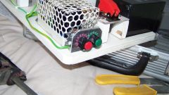
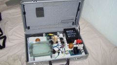
My attempt at building a Kirlian imaging device, using advice from RMC.
This had to be robust, portable and light enough so my niece could take it to uni as part of her masters degree in forms of hidden energy.
Although I used to do lots of electronic wirework in the 60’s (I was building electronic organs when the first IC’s were introduced) I don’t really have much understanding of how it works, so I stick to just building the easy bits and buying the rest. All mounted on 9mm ply, the doorknobs are actually extraction enabling devices to lift it out of the case.
Parts list:
4ah SLA battery
RMC high voltage coil
RMC PWM-OC10A
Two LED rocker switches for positive and negative isolation from battery to PWM rated 12V 10A, although only the LED on positive lights up, any ideas here?
Top Gun coil isolating switch with red cover rated 24V 16A . Bit OTT, but I thought it looked cool
DIY insulator stacks made from slate mosaic tiles drilled and screwed to board with MUPVC angle to locate and hold the plates.
2 DIY discharge plates, visible area 90x120mm, 3mm glass, 3mm acrylic spacer. Brass and copper electrode as picture. Each plate contains approx 35ml of salt water.
Salt water solution: I used Wiki answers and came up with 100ml of water could contain 38gm of salt. Tried this and left it overnight, come morning it had a 5mm salt sediment and was totally opaque. I decided to add water at 10ml a time, stir and leave it, during the day I added a further 60ml water, it seemed to be clearing, left overnight to settle. Finished with 1ml of sediment and the water was almost clear. This worked out at 24gm salt per 100ml water.
I did do other things during the day, I am not that dedicated.
Test run next.
Colin Cade,
The terminal furthest from the output is the GND terminal. Looks fine to me.
Mario Ramirez,
Batteries don’t have an A rating it is Ah (Amp hours) which is quite different. You can use either of those you suggest, one would just last longer.
have made electrode as picture, with wire running round inside edge as suggested earlier. 3mm glass, 2mm acrylic spacer/frame, brass strip with 1mm copper wire, before I attach HV lead, fill and vent points, just want to check if its ok.
Would you have any recommendations on what type of battery would work best with the high voltage coil you offer on your site (HV-SC20K)? Would a 12v 7A battery just last longer than a 12v 5A battery or is there a chance of damaging the coil? Many thanks for all the help! -Mario
thanks, will do that, PPM and coil arrived today, excellent service.
The coil doesnt seem to have + or – marked on the input terminals, how can I tell which is which. I couldnt find a data sheet on your site.
If you put the switch on the ouptut side, it will allow the fan to keep running and cool the PWM-OC10A when the coil is off.
2A may be a bit to small. You could find that the contacts will stick and you wont be able to switch off. You should use something that is rated for more current than you are excpecting to pass through it. I would use 5A. Also the switch should be a locking type so you dont have to hold your finger on the button.
I have decided to use your High Voltage Spark Coil and a OC10A PPM. I noticed that you recommend fitting a push switch to turn the unit on while taking a picture, can this be anywhere in the circuit or is there an optimal place for it. Would a bell push type switch do? usually rated at 24V 2A. cheers
thank you for the advice, will alter my plans accordingly.
Any shape is fine. You can use two coils for more power and brighter images, or just use one coil and have one plate connected to ground.
The PWM-OC10A will power ignition coils only intermittently due to it getting hot. With the large old style ones this will happen even more quickly. I would recommend using the PWM-OC30A if you want to drive larger coils as this can tolerate 4 times more average current.
It is possible to take images of fingertips but there is a high risk of an electric shock. If you do it, it is at your own risk. I will give you some guidelines but I can’t guarantee it is safe.
If you were to directly contact the HV output whilst your body is grounded, the shock would feel intense and would startle you. Your reflexes would cause you to jump or move suddenly. You may inadvertently fall or break the glass. This is what causes the risk of injury rather than the electricity its self, although there is no guarantee of that.
Do not touch anything else when your finger is touching or close to the live plate.
Stand on an insulating surface like a thick plastic sheet.
Make sure the finger is in the middle of the plate and no part of you is close (within 3cm) of any wires or the edges of the plate.
You will need a camera with a timer to take the photos so that you don’t touch it when you are touching the plate.
hi, I have some 3mm glass 110x150mm is there any reason why i cannot make plates that are rectangular rather than square? I am making two to use together as suggested above, should i use two batteries and two coils (if neccessary would go for old ignition coils, would they have to be the same model). and how should i wire them, I intend to purchase one of your PWM-OC10A PPM if this would drive the coils ok. you mentioned that the plate would be live and not to touch, but state that you could take pics of your fingertips. if all the metallic parts are insulated, would it be safer? many thanks in advance. I have read much of the faqs, but have been unable to get a clear picture.
I don’t know. I have not taken such measurents. It will be the current that will increase in porportion to the plate size, the voltage can remain constant.
Great, thanks for the help! Another question — any idea on surface area relative to voltage requirements? “So many volts at so much current for so many square inches of copper clad board”? I’d like to try something in the way of interchangeable discharge plates but don’t know what to expect at 3″x3″ vs 8.5″x11″…thanks again!
30mA seems quite high. maybe 1mA is more likley allthough the actual current drawn will depend on the size of your sample and plates.
100kV is not really needed, about 20kV is fine. If you really want such voltages just keep the current below 1mA
So overall what is the range of voltage and current being passed from transformer to the discharge plate? I see as low as 12kV and 30mA, from a safety point of view it’s really the amps that are the concern right? What’s the highest voltage (and highest current) that are useful and safe? Can I aim for 50-100kV if I keep it under a certain current?
aspera,
I’m not sure, the diagram is too small. Email us a larger version.
Bara,
Please describe the configuration of your existing setup.
Salt plate Connection to Kirlian Camera (not the Polaroid type)
How can an electrotechnical layperson connect the salt plate to an existing Kirlian camera, which has a grounding wire and 110V connection. For example, I would like to see foot energy through the glass plate.
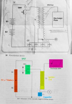
I obtained this schematic for a portable kirlian device from “The Kirlian Aura: Galaxies if Life,” a book published in the 70’s. I had a friend compile the components into a parts list:
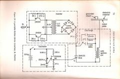
2 – 2n554 transistors
1 – 6v battery
1 – 22v battery
1 – transformer (6v to 120v) 6.3vac at 1/3 or ½ and amp
4 – 1n4004 diodes
1 – unijunction transistor (2n2646)
1 – 250k potentiometer
1 -.25uF 600v capacitor
1 – .5uF 600v capacitor
1 – 1uF 600v capacitor
1 – 2 uF capacitor
2 – 39ohm resistors
2 – 270ohm resistors
1 – 100ohm resistor
1 – 27ohm resistor
1 – 56k resistor
1 – 250k resistor
1 – 2n4101 is a Triac aka SCR
There’s parts of the schematic that are unclear to us in the inverter. Can you decipher it?
Thanks!
-Michael
Yes,have been using Method A pretty much.
I’ve been thinking on it and I was wondering just what you have postulated – So ill try isolate my worksurface with some ceramic kiln spacers and maybe a glass sheet…
ahh and just been looking at the weather reports and I think the humidity isnt helping much either, So i’ll try running a dehumidifier and room heater in my sealed room for a couple hours before I next run the device.
Cheers Again
Ok, I’m assuming you are using ‘method A’ shown above. If you are getting good sparks like you describe then i am sure your HV PSU is fine. The positioning of your HV plate might be causing problems. It will be a high potential compared to everything, that includes your desk or table. A large flat conductor being pulsed with high voltage will leak current to almost anything unless it is very dry or well insulated. I’d recommend standing the HV plate on some glass or ceramic spacers. You could even heat them for a couple of mins in an oven to make sure they are totally dry on the surface. These ceramic standoffs are ideal for it. Also make sure your HV cables are not touching the table too.
Yeah, fax paper was just giving me varying degrees of burnt mark.. abandoned that now.
No, I was not using a transparent electrode, at the moment I’m just trying to get some contact plate electrode images. I got two done today, with a coin placed directly onto B and W photo paper but the images were faint and lacked clarity, both after a 1min and 2 minute exposure. I will try some longer exposures tomorrow, and perhaps use a thinner piece of dielectric plastic.
Still not seeing the corona visually though, perhaps my circuit isn’t operating at optimum criteria for corona formation – though the sparks are visually impressive when HV supply and ground are seperated by an air gap, and it is definately pulsed. so I’m not sure what I can do to improve it.
Once i begin to achieve reasonable images with the plate method, then i will build myself a transparent electrode (noted, I will use glass not acryllic, thanks for the tip)though currently i would certainly not get any image which resembled yours after a mere 10seconds of exposure i think.
Do you have a transparent conductor over the object?
Fax paper will work but its tricky and the images aren’t great. The corona you are trying to see is actually a partial plasma which is very hot. If this is plasma concentrates in one spot, it will just burn the paper. You need to make sure there is an even contact all over the sample otherwise it wont work.
Don’t use acrylic, it will be melted on it surface making it unclear. Even glass sheets can be melted when doing this. I don’t mean melted like it will bend or anything, just permanent marks on the surface.
Hey there guys,
First, in terms of the quality of material and explaination on here, I have to commend you – and also on your incredible patience/persistence in answering some people’s questions. Even if some of those people ought not to be anywhere near DIY HV supplies.
and Secondly I would like to add to the long list of questions with a few slightly simpler ones.
I am using my third homemade HV supply, which is a slightly modified old colour TV, with a non rectified flyback transformer, which will spark to ground about 35mm, and sounds (i have no way of measuring/controlling) like it is well into the middle of the 50hz-20khz range – and i would estimate that it is in the 10-15kV 1-5 milliamp range.
1. From what i understand of Kirlian photography/electrography my HV source should be suitable, but with a grounded object on the dielectric surface of the plate and 5 minute dark adjusted eyes – i cannot visually observe the corona effect/streamers, any idea what might be wrong?
2. In a book i was reading they mentioned simple corona images might be produced with thermal transfer/fax paper, but in my setup this doesn’t seem to work (aside from directly turning/charring when touched with a uninsulated spark) have you tried this method, if so any pointers?
Tomorrow I will try some contact electrography/gramy with Black and white photo paper and this HV unit and hopefully see some results, as unfortunately with my lower Voltage (2kV), lower frequency units i got next to nothing when i developed my paper.
Await your advice and response – and may try to build a transparent electrode from acrylic this week.
Thanks
Alex
Yes. The most recent photos on the plasma page are all digital.
I wanted to buy a Kirlian Camera but I found out that the film is not going to be made anymore because of the digital cameras. I am technically challenged. Does this work with digital??
Yes. The requirements for good results are as follows:
Adjustable shutter speed
High ISO
Wide Apature (Important)
Self timer or remote (to avoid vibration)
Zoom or Macro lense
I think your camera has these features so it should do ok. Please upload a pic you are successful. The most recent of my plasma photos were taken with a Pentax K10D with a 2.8f apature lense.
You can see an example setup here
Did I miss it. Can this photography at all be done with a midlevel digital camera? I mean, with software, I suppose? (Thinking of oraganic foods photos.)
What I have is a Sony DSC-H9
But careful… Huge current… Do not touch… You could maybe experiment with much lower capacities… 1 nF, or something…
Mains – Dimmer – Capacitor (few uFs, say 4.7) – coil – Mains…
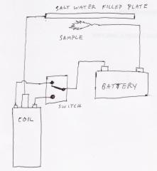
I assume you refer to the diagram ‘barry’ posted. This shows a battery connected to an ignition coil using a switch. This will not work. My reply states that the power to an ignition coil needs to be pulsed rapidly using a specialized circuit.
The cheapest ignition coils will be found in a local scrap yard for just a few quid (bucks). The best way do drive the coil is with an adjustable frequency circuit, but the cheapest way is to wire up a relay to self oscillate. A self oscillating relay will pruduce some HV, but I can’t say how well it will work for a kirlian photo.
Hi, how are you doing I appricaite the info you gave me, but it is still confusing. On the diagram it shows a battery for a power supply, but in one of the message you sent, it says you cant use a battery. So what type of inexpensive power supply can I use,and also the other parts I need to make it work in details from start to finish please and thank you.
Yes, if you remove the film as described in ‘Method A’
can I use a reglar poloriad 600 exposure camra
thank you 4 your time and help
You can email us using the form on this page.
It needs to be at least 10,000 volts. I don’t know where you could get one so cheap.
You don’t need 2 wires inside the plate. If you have more than one, just join them together.
how do you hook up a hv plate that has two wires in it.
where can i get 1000 voltage supply for cheep like 10 or 20 max dallors from
do you have a number or email address that i can reach you from
You can’t. You need some sort of device to generate a high voltage. This is mentioned at the top of the article.
where can i get a battery for cheep that has 1000 voltage
Any camera which has a feature for adjusting the exposure time to several seconds.
what type of camra can i use.
One wire from the High Voltage Supply connects to the electrode(s) in the water. Another wire connects from the sample to ground/earth.
A car battery will not work. You need at least 1000 times more voltage.
can i use a car battery to power up the hv plate.if not wath can i use.
how do you houck up the hv plate with 2 wires.how much salt warter do i have to put in the plat.
Try this simple circuit using only a capacitor (ignition condenser is good), relay and battery: http://tesladownunder.com/HighVoltage.htm#Sparks%20for%20beginners
The relay coil is wired in series with its normally closed contacts forming a buzzer. The contacts are bridged with the capacitor and the ignition coil is paralleled with the relay coil. You might want to place a 10 watt resistor in series with the ignition coil to limit the current if necessary.
An ignition module would not work as it still needs a timing signal which is usually generated from some moving part in the engine or a circuit like linked above.
You could use our Power Pulse Modulator as long as a snubber is also used or the power is kept low. The snubber design would depend upon the type of ignition coil you have and the frequency you wish to use. If you know these parameters we can also provide a snubber. If you don’t know you could buy one of our ignition coils and we could create a matching snubber for it.
I have little experience with circuits. Would an ignition module suffice, in place of this circuit? Obviously it would depend on the module model, but do you know an approximate method of wiring the components I mentioned earlier (including the module).
thanks again.
Check this Ignition Coil Driver Circuit
How would I connect a 12v battery, a car ignition coil and a car ignition module to produce the HV required. Basing the circuit on a car ignition system, excluding the distributor. Do you have any diagrams for something like this? So far my search has been unsuccessful, would appreciate any help,
many thanks.
Yes, it will help significantly if the sample is grounded. We are based in UK nr Manchester if you wanted a demo
does the leaf have to be hucked to a ground wire. I did the project but i didi not see the leaf glow. is ther a way u can met me some where so u can help me. if not can u give me any suggestion on what i’am doing wrong.
thank u 4 everything.
No. You place the window on top of the sample so you are looking through the window to see it.
does the plant have to be in the HV plate
Any salt will do.
does the salt warter have to be salt warter from the ocean or can I make it from regular salt.
The frame I used had the same plastic frame but with part wrapped in foil for the electrode. This worked quite well, but salt water will corrode Aluminum so the electrodes will have a limited lifespan. You could use a solid metal or carbon piece, or just empty out the salt water when it is not being used.
the pictur u sent me has something that says electrode/fram what is that and can I use aluminum foil?
I just wanted to say thanks 4 every thing.
marnae green, GRIM.657,
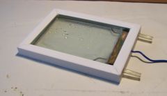
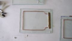
This image shows the assembled piece (left) and an exploded view (right) to show the individual parts. Silicon sealant or epoxy resin is used to fix and seal all edges.
Salt water can be poured into one opening using a funnel or syringe. When the water reaches the air outlet, both tubes can then be sealed.
You must ensure that the inside edge of the electrode is in contact with the salt water when in use.
It can be quite tricky to seal the frame effectively and without making a mess in he viewing area. We have some electrodes ready made which are double sealed for durability and come with a large filling syringe. Click here
I’m also curious about the glass… specificaly how thick you recomend it should be? (both the thickness of the glass, and how far apart the 2 pieces of glass are)
Ikinda get what it said to do but, I still dont know how to make the plastic part to wher you can fill it with water.If it is possible can you show me a different pictur on how to make the plastic part pleas and thank you.
GND represents Ground, Earth, or 0V of the power supply.
on the picture below it has something going to GND. what does the stand for.
Information is above
how do you make a transparent HV plat using salt water.If it is possiable can you tell me step by step on how to make it?
The total volume of salt water needs to be quite small. The electrode used here had a gap of 2-3mm. Yes there must be a wire in contact with the water.
The exposure depend on lots of things like the type of camera/film and the power in the HV power supply. This image was about 10 seconds with ISO 800 film.
When building the transparent conductive plate what is a good gap (where the water with salt goes)bewtween teh two glasses? and electrode (Wire) is in contact with the water? Also for te hexposition how long shall be to get the foto?
Frequency is in the audio range for most ignition coils, so say from about 50Hz to 20kHz. For kirlian photograpy it is often best to use the higher frequency end of that range.
Duty cycle is usually 50% or lower to prevent the transformer core from saturating.
For the Pulgenerator what can be a good starting frequency to test? I know that this will depend on the Coil used but can you provide me with some guide.
The duty cicly shall be less than 50%?
Ideally nothing larger than an Ignition coil or flyback transformer driven from a low voltage source.
what kind of transformer should used?
The output voltage should be at least a few kV. 10kV is not uncommon.
The output must be current limited for saftey
A small battery operated transformer such as an ignition coil will be low current by design.
one more question my friend!
1) what should be the voltage of the transformer?
1) – A coil/transformer is needed to step up a low voltage source to a high voltage.
2) – The image is formed bacause there is a high voltage between the sample and the salt water. The voltage needs to be high enough so that the air becomes ionized. The purple glow is called corona discharge.
3) – This would be part of whatever high voltage supply is used.
4) – A small volume of salt water is better
i am sorry to bother you again. i hav some more doubts.
1) can i use a capacitor instead of a coil?
2) how can the image be formed if the sample is not in touch with the salt water?
3) what should be the power of the battery?
4) will increase in the quantity of salt water give better effect?
bye, and thank you for answering my previous questions.
The salt water is entirely contained between two sheets of glass. This is then placed over a sample object so that you can look through thee glass to see the effect.
hi
i hav a few doubts
1) where should the sample be placed? is it like this? sample above the first glass and glueing the frame on it and filling the salt water between the frame and the second glass piece?
2)should the sample be in contact with salt water
plz reply soon
I wouldn’t expect that the concentration of your saline solution is the problem, but it could be the volume. With a larger volume of water, more current is necessary because it tends to act like a ground plane absorbing the energy.
An alternative is to switch the polarity of the setup so that the window is connected to ground and the sample is connected to the HV source.
This can be more tricky, but the effect is almost the same.
The corona produced is only very faint. It needs to be viewed in total darkness after your eyes have adjusted to the dark. To take the photos shown here it was neccesery to leave the camera shutter open for several seconds just to get enough light.
The sample needs to be in direct contact with the glass of the transparent electrode. As much of the sample as possible should be touching it to get a good image.
I am now powering my circuit with a 9V battery and have used a relay connected up to pulse the flow. I am using the charger to power the relay because I cant work out how to do otherwise. I am getting good continuous sparks now.I have just connected up a leaf to the ground and started it all up. Nothing! I now suspect that my solution between the glass plates is not conductive enough. Is there another conductive liquid that can be used? Also, how good a contact does the leaf need to have with the conductive plate. Should it be squashed flat against it or what? Thanks in advance.
The GND connections should also both connect to the battery -ve terminal.
A 6V charger may not be able to provide enough current. A 12V battery is reccomended.
You are unlikley so see any kirlian type photos when using a switch or a connector. You really need to pulse it at a higher frequency with a special circuit. The best you can expect with your current setup is a few sparks and flashes.
I have put together the revised circuit you posted but I am still getting no spark. I am a complete novice so maybe one of the following points will immediately reveal to you why my circuit does not work.
a)For a ground I have hammered an aluminium pole into the earth just outside the shed I am working in.
b)Instead of a battery I am using a 6 amp battery charger.
c)Instead of a leaf for a subject I have just placed the end of the HT lead very close to a wire connected to my ground.
d)Instead of a switch I physically touch the chargers positive cable on to the coils terminal to make and break the circuit.
Please help
The coil needs to be pulsed to produce a constant supply of HV. If you just connect a battery to it using a switch (like shown in this diagram) , then you will only see a single spark when the switch is released.
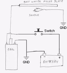
The Ignition coils output voltage is proportional to the rate of change of input current. This means that when you release the switch, the current will change from fully on to zero in a very short time, causing a high voltage on the output.
The other circuits you’ve seen are used to switch the power to the coil on and off very fast so that there is constant(ish) output. You can see example circuits on the ignition coil driver page, and the pulse generator page.
I have made a salt water filled plate and have managed to find an automotive coil from a car breakers. Can you please give me some help with the circuitry. I have tried the attached circuit but it does not work. I think that perhaps I am being a bit too simplistic. I have seen various circuits, some involving capacitors and and some with a lot more complexity. I am keen to keep things as simple as possible. Any advice would be great.
It’s not neccesary to use two electrodes like we did. The device shown was also used to contain a vacuum which could have high voltage between the terminals.
For the saltwater filled one, you just need to have a wire touching the water somewhere. It may help to use a long wire, or even loop it around the inside edge so that the electric field spreads more uniformly.
With the one shown, the electrcal connection was made to just one electrode.
Following my previous post – In the picture of your conductive salt water plate I see what I suspect is the water inlet with a plug in it but there are also what looks like 2 wire connections. One on the left and one on the right. Why 2?
Excellent service you are providing here. Sorry, but I have yet another question.
The electrical connection to the salt water – Is it just the bare end of the wire that is in contact with the salt water or do I have to make a bigger contact with copper sheet or something?
You can just use ordinary salt. The more salt you add, the more conductive the solution will be. You could keep adding salt to hot water until no more will dissolve. Let it settle and cool before using it otherwise it may remain slightly murky.
thanks for that info, thats a great help. another question though…do you have to use sea water or can i just make some salty water using salt and water..if so how much salt and how much water? thanks
The two sheets of glass used to contain the salt water should be seperated by the smallest possible gap.
This can be difficlut in practice as a very thin space will be hard to fill with water without sealing in bubbles.
The one shown one this page has a gap of about 3mm which was simply determined by the thickness of the plastic used to make the inner frame.
How big a gap should there be between the 2 plates of glass with your salt water plate?
Step 2 – Driving 180 out of Phase
Now the transformers are being switched at the same time you can reverse the connection to one transformer and this will change the phase relationship of the transformer outputs.
Basicaly now when the transistors send a pulse to the transfomers the outputs will be of opposite polarity. Each indivitual transformer will have the same output voltage relative to ground as before, but now they are out of phase so you can measure the voltage between the two HV outputs.
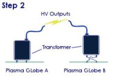
For example: If the normal plasma globe (pgA) is currently outputing +10kV, the other (pgB) will be outputting -10kV, making a total of 20kV of potential difference between the terminals.
The polarity of the outputs will switch between +ve and -ve thousands of times a second, but because they are both being driven from the same signal source, therfore they should allways be equal and opposite.
Please note: These instructions are intended as a guide, and there is no guarentee that this will not damage your plasma globes, set on fire or electrocute you. By following these steps you agree to be held responsible for your the outcome of your activities.
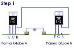
Step One – Phase Matching
This diagram shows the transistor on each plasma globe. It will be attatched to a metal heatsink which should be left in place. I’m not sure if the transistor will be a TIP142, it depends upon your globes manufacturer. If the E, C, B pins are not marked on your board, you should look up the datasheet for the transistor you have on Google. if you cant find this, let me know and I’ll have a look.
Here you are disconnecting the base (B) pin of the transistor of plasma globe B (pgB), and connecting it to base pin of plasma globe A (pgA). This is so that the signal source that is driving ‘pgA’ is simultaniously driving ‘pgB’.
You also need to make a ‘common ground’. This is done by connecting the -ve terminal from each plasma globes together. The -ve of the power connector is usually the outside terminal.
These two plasma globes are now being driven in phase. This means the output voltage from each is the same level at the same time. You could now connect the two outputs together to effectivley make a supply with the same voltage, but twice the current of a single plasma globe.
Step two is an additional modification that can be done to get a higher output voltage.
My message was about to get more output voltage you said that I would need to drive the tranformers 180 degrees out of phase from each other.Unfortunately I have not got a clue how to do that.You also mention that you may be able to upload a diagram for me.
Please could you do that and also if there is any other information that you may think may be helpful. It would be very much apriciated.
Many thanks
Carlos
No it is not possible. There are no known scientific methods for visualising “auras”.
Anyone claiming to sell such devices is giving out false information.
Any subtle electromagnetic fields from biological entities would be massivley overwhelmed by the techniques that are commonly used for “visualising auras”. Even the electrical background noise in a house would be much more detectable than anything given off from living organisms. This makes it practically impossible to make visualisations of any subtle energy surounding a human.
good afternoon to all,
I would like to know if one is possible to capture the image of the aura human being using computer webcam.
my e-mail: lrvcs@hotmail.com
bests regards!!
luiz renato
If you connect the outputs of two plasma globes, the combined voltage/current may be unstable. This is because both transformers are being driven independantly so the driving pulses will probably not be in phase with eachother.
To get more output voltage you would need to drive the tranformers 180 degrees out of phase from each other.
To do this you need to drive both your transformers from the same signal source. If you are not sure how to set this up, let me know and I will upload a diagram showing how it can be done.
How can I connect together to get more high voltage, 2 plasma balls to create a kirlian photography.Each plasma ball has 1 cable out which is the high voltage terminal (TC).
By connecting them together will I get double voltage output?
Please can someone help?
Many thanks