DIY Plasma Gun II
The DIY Plasma Gun II is an improved version of a compact, portable, spark gap Tesla coil which can create jets of high voltage plasma and even doubles as a flame thrower! This updated version of our hand held Tesla Coil has been optimized for improved efficiency and gives a larger output than the previous one. It is also now even easier to build! You can find the old version on the original Plasma Gun page. We decided to stick to a spark gap type Tesla Coil for this plasma gun as it is considerably easier to build and more reliable than solid state controllers. We will however produce a solid state version in future.
This page should show you all you need to know about how to make a plasma gun like the one shown here. Hopefully it will also teach you the science behind it so that you will know how it works. Remember that this is a dangerous high voltage project and should not be attempted by inexperienced people.

What does the Plasma Gun do?
This plasma gun is essentially a small battery powered spark gap Tesla coil. Its inteded purpous is more for education, than an actual function. We hope that is is a fun and interesting project and that you will learn something from it. If you make your own plasma gun, please post a picture below!
The plasma is made by ionizing air around the output terminal of the Tesla coil. The high frequency, high voltage electricity is able to form streams of plasma that can be made to spread out, or be directed forward along a flame or stream of gas. This directed plasma channel can actually have a useful function in some industrial processes known as “plasma surface treatment". When the jet of plasma is directed at a surface such as a plastic bottle, subtle changes will occur in the structure of the material on a very thin surface layer. Typically these changes will make the surface more porous, or easier to print onto.
Anyway, enough of that, we know you really want it just becasue it’s cool, and you want to build your own plasma gun! On to how it’s made…
![]() Warning: This project involves dangerous high voltage electricity!
Warning: This project involves dangerous high voltage electricity!
How it’s made
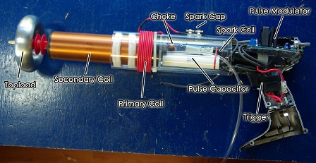
High Voltage Inverter
For converting the low battery voltage into high voltage for charging the primary capacitor.
This part of the plasma gun does the main power conversion by pulsing a high voltage ignition coil. Pulsing the spark coil will step up the voltage from the battery to about 20kV which is used to charge the main capacitor. This capacitor is later discharged into the primary coil of a Tesla Coil to further increase the voltage.
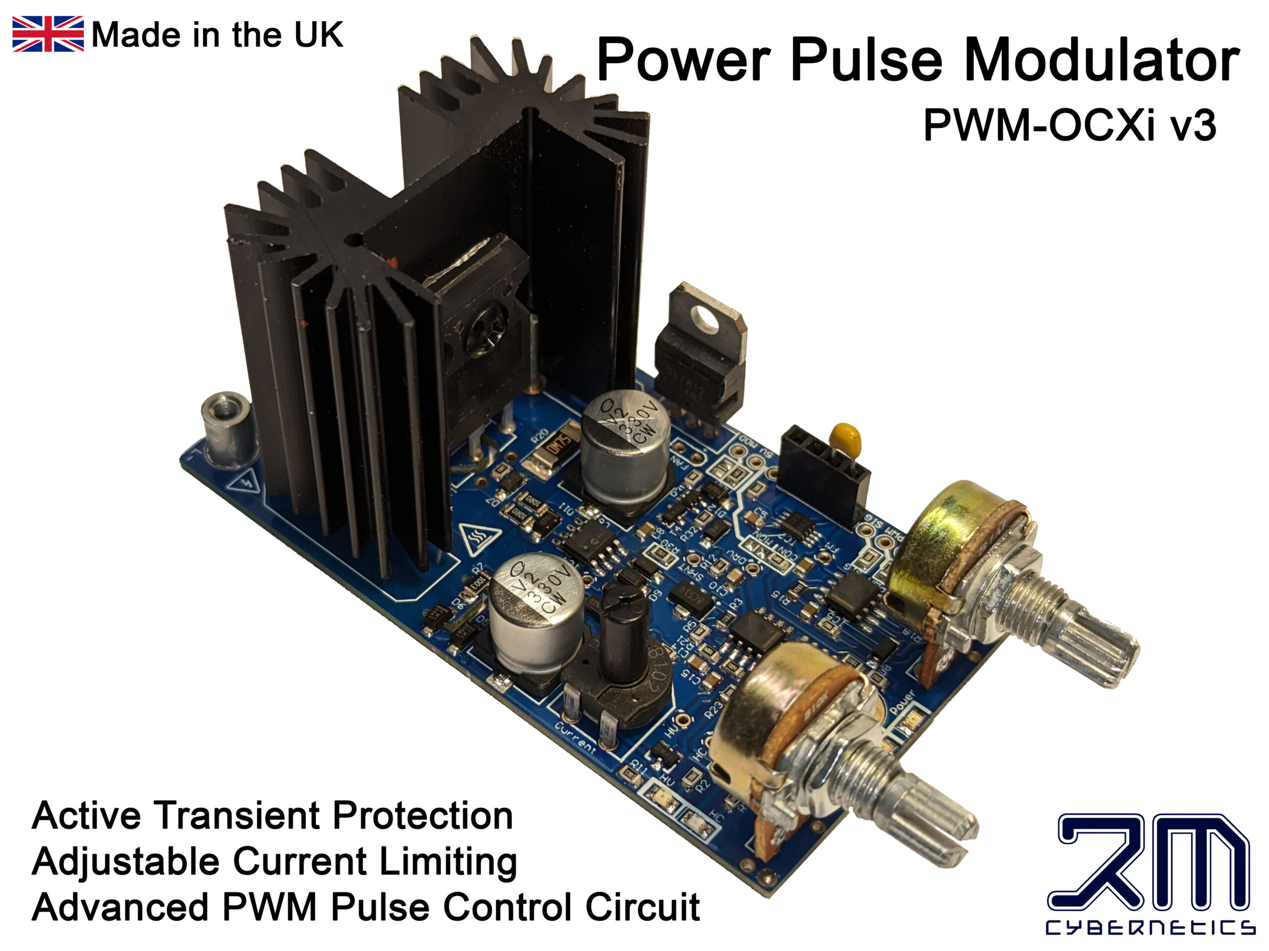
For this we used a Power Pulse Modulator (PWM-OCXI) as it is really simple to use and will give a really powerful high voltage output from an ignition coil. The PWM-OCXI is considerably more powerful than the PWM-OC10A which was used in the original plasma gun project and therefore improves power throughput significantly. This circuit was mounted in the back end of a cordless drill casing so that the control pots and LEDs were accesable from the back. At the side of the drill casing a small switch was mounted that could be used to switch the circuit on and off. This serves as a safety to power down the plasma gun when not in use.
 The power to the ignition coil was fed directly from the drill battery via the original trigger switch, into the L- connector on the OCXI. By connecting like this, the control circuit and its cooling fan stays active between times when the plasma gun is fired.
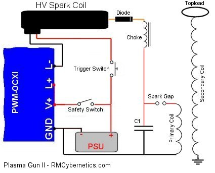
It is neccesary to add a high voltage diode to the output of the ignition coil so that a capacitor can be charged. For this, the rubber end of the ignition coil was removed, and the diode connected to the spring inside the tip. The tip was then filled with epoxy resin so that the high voltage would not flash over the body of the diode. This also helps to cool the diode by absorbing heat from it. The cathode wire is left protruding from the resin so that it can be connected to a small inductor. This inductor serves as a choke to protect the diode from the high frequency currents in the primary circuit.
Primary Tank Circuit
For storing energy in a resonant circuit to be rapidly discharged in pulses.
The primary tank circuit here consists of a high voltage capacitor, spark gap, and a coil of wire (an inductor) known as the primary coil. When the capacitor becomes charged to a high enough voltage, the air between the terminals of the spark gap will break down with a loud bang and a bright flash. During this very brief flash, the energy in the capacitor will be moved into the primary coil and then back again over and over at about 1,000,000 times per second! This frequency of 1MHz is determined by the sizes of the capacitor and the coil and is know as the resonant frequency. The resonant frequency of this inductor capacitor combination can be calculated as follows;
Primary Circuit Resonant Frequency
f = 1 / (2 x π x √(L x C)) = 1,000,000 Hertz
Where f = Resonant frequency, L = Inductance and C = Capacitance
The value of the capacitor is fixed, and the inductance of the primary coil is determined by its size and the number of turns of wire used to make it.
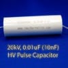
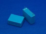
The capacitor used was chosen for improved efficiency over the ceramic capacitors used in the original Plasma Gun. By using a quality polypropelene capacitor with a low ESR and low ESL, the losses in the high frequency resonant circuit are reduced significantly. This means more awesome sparks!
When choosing the values for the components a number of factors must be considered. Some factors are fixed, while others can be varied. The table below details some of the points which must be considered.
| Parameter | Notes |
| Physical Size | The physical size was chosen to be limited to something that can be held in the hand like a gun. This size limit means that the secondary coil of the Tesla Coil must either have relatively few turns, or must use very thin wire so that more turns can fit on the form. The power supply will be limited due to size, so it is important to choose a powerful battery. |
| Secondary Coil | The design of this coil determines the resonant frequency of the diy plasma gun and therefore will limit your options for other parts in the circuit. Thin wire would cause losses due to resistance, while thicker wire will mean less turns and therefore a higher resonant frequency. |
| Resonant Frequency | The size constraint means that the resonant frequency will be relatively high. Such high frequency will cause more losses and increased impedance. It also means that a large primary voltage is needed to get a good current to flow in the primary circuit. |
| Primary Circuit | The primary circuit needs to be adjustable so that it can be tuned to match the secondary coil’s resonant frequency. Without proper tuning the plasma gun will not give a good output spark. |
Secondary Coil
Self resonant circuit which magnifies the primary voltage so that it can discharge as plasma streams.
By using 0.25mm wire there is a reasonable amount of copper for conducting current through the coil but due to the small size, only 750 can be fit onto the coil. Without a discharge terminal (topload), the resonant frequency is around 1100kHz. Such a high frequency introduces losses so we can reduce this frequency by adding a larger topload. The toroid used brings it down to a more reasonable 900kHz.
Due to the high electrical stresses, it is important to insulate the coil well with multiple layers of varnish. Although this introduces more dielectric losses, it is essential for preventing sparks flashing over the surface of the coil and for protecting the windings.
Breakout Electrode
For concentrating the electrical discharge in a focused place.
By using a large topload, the electrical field is spread over a large area and will not break out in to arcs until the voltage is very high. While this is advantageous for increasing arc length, it also increases the chances of the arc discharging back towards the coils. The breakout point creates a localised area of intense electric field which will ionise the air more easily and force the discharge away from the end of the plasma gun.
The electrode is fitted with a pipe so that gas can be ejected from the the tip. Some gasses such as Argon or Carbon Dioxide will ionise more easily than air. When ionised it will provide a conductive path, allowing the plasma to reach further from the coil. If butane is used as the gas, it will ignite and also conduct the electric currents. One difficulty with this is that as the arc length increases, it lowers the resonant frequency of the secondary coil causing it to drift away from the resonant frequency of the primary circuit.
| PARTS LIST: You can buy most of the parts from us directly. You will also need other parts such as the drill. Below is a list of parts available in our shop. | |
| Power Pulse Modulator (PWM-OCXI) | |
| 1000uF Power Capacitor | |
| HV Pulse Capacitor (20kV, 10nF) | |
| HV Spark Coil | |
| HV Diode (30kV, 100mA) | |
| Choke (390uH) | |
| Small Bolt (for choke core) | |
| Adjustable Spark Gap | |
| Silicon Cable (for primary coil and other wiring) | |
| Secondary Coil | |
| Toroid | |
| HV Insulators |
Tuning
Precise tuning of the resonant circuits for max output.
There are two resonant circuits in the Tesla coil part of the plasma gun which must be tuned to the same frequency. If the frequencies are not matched, the energy transfer will be very poor and your plasma gun will be little more than a noisy spark gap. The secondary coil’s resonant frequency is pretty much fixed. It is possible to make small adjustments by changing the size of the topload, but this is not very practical to do. Instead, it is simpler to choose a primary capacitor, and then adjust the number of turns of the primary coil to get the right resonant frequency. This can be done with a little calculation and then trial and error, but can be quite time consuming.
We used a signal generator and osciliscope for tuning the plasma gun, but it is possible to do it with a little circuit such as a Telsa Coil Tuner although it is not easy. Even after tuning, you may want to tweak the number of turns on the secondary coil to achieve maximum output. When tuning the secondary, keep it away from yourself or other objects as the proximity may alter the resonant frequency.
Once tuned you can also adjust the Power Pulse Modulator so that you get some good resonant charging of the capacitor. At certain frequencies the system will be more efficient o by slowly adjusting the frequency when it is running, it is possible to find the best setting. While making the adjustments, the spark gap firing rate is observed until a setting is found where the maximum firing rate is achieved.


where do i get the products not provided here and also what isn’t?
is there instructions of some sort even if they’re vague(but more detailed than this) I just don’t feel safe assembling this
We don’t have any further instructions. Tesla coils are dangerous, so if you do not feel confident, I would not recommend making one.
Choke (390uH) ,How much of a current?
Needs to be rated for 5mA or higher.
No. The air is already ionized, a diode will do nothing useful.
If I have a 5 watt diode and use it with this plasma gun, can I increase the range of the plasma through ionization? If so, by how much?
The coil will pull about 5A from the battery, so only 60W.
Oh, 12V? And how many watts are needed with 12 V? So, can be a few batteries enough?
12 to 20V input should be fine.
How many volts are needed to source? Is it necessary to optimize? Or this is not important, is it?
The choke is there to protect the HV diode. The choke prevents the hight frequency current from passing back to the diode. Its inductance value is not critical.
Could someone be so kind as to maybe tell me a little more about the choke that is needed? Cheers
The battery powers the OCXi circuits using the V+ and GND connection. The battery is then connected to the coil in pulses via the L+ and L- connectors. The OCXi works like a switch; L+ is the same as battery positive, and is connected to one side of the spark coil. L- is swithed to GND on each pulse thus allowing current to flow in the spark coil.
Hi, could you clarify a couple of things? Does the current from the drill’s PSU pass through the spark coil first before it powers the OCXi through the L- connector? Does the OCXi then send the voltage spikes out from the V+ connector and back through the spark coil?
This version uses a cable to connect to a real earth point such as a metal filing cabinet. It is too powerful really for grounding like in v1. Regarding zapping yourself or others with it, I can only say that it not safe to do so, and it is quite possible to damage phones just from the radiated electric fields without direct contact.
I notice the RF ground is through a metal plate in the handle. So if I’m holding this in my right hand and it discharges/arcs to my left hand, how dangerous is that?
Also, how much RFI will this produce? Will it damage my smartphone if I have it on me? Will it damage someone elses’ phone if the top load discharges to them, even if it doesn’t actually strike the phone? Will the oblivious stranger standing behind me who has pacemaker drop dead when I discharge this near them?
(I don’t have much (any) experience with high voltage, sorry if these are foolish questions)
has anyone attempted to make the DIY Plasma Gun II ?
I would love it if someone made a video or complete instructions on how to make this device.
It just connects at the input to the circuit. It helps smooth the DC supply. Yes the OCmi will work, but it will be significantlt less powerful. You will also need to be careful not to turn up the duty too high as it could damage the circuit.
I can’t find the 1000uF power capacitor in the circuit diagram. What function does this capacitor have and how is it used? And can I use the PWM-OCmi for this Gun?
We have no step by step instructions. We hope that you will take the time to study more about the subjects so that you can understand the project rather than just following some steps.
Has anyone created a step by step video (Youtube, etc…) highlighting the assembly of various kits?
Some of the projects look very interesting, but I need more information before I would be comfortable assembling them.
Thanks!