DIY Lifter – An Electrohydrodynamic Thruster (EHDT)
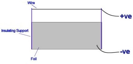
The diagram below shows a EHDT in its most basic form. It consists of a fine wire, suspended above a sheet of Aluminium foil, by a lightweight insulating support such as balsa wood. If a high voltage DC source is connected as shown, a thrust will be produced, propelling the device in the direction of the positive wire. This thrust is due the motion of air, or any other dielectric (insulating) fluid around the device, as described below.
![]() WARNING: This project requires the use of dangerous high voltage electricity!
WARNING: This project requires the use of dangerous high voltage electricity!
The top sharp electrode ionises the air. If the electrode is positive, free electrons in the vicinity will accelerate towards it, and strip off other electrons from the air molecules around the sharp wire. A cloud of heavy positive charges is thus formed, and the avalanche of electrons approaching the sharp electrode account for the corona & ionisation current.
In their mad rush from the ion emitter to the smooth negative electrode, the positive ions bump into neutral air molecules-air particles without electric charge. The force exerted on them by the electric field is offset by the force of friction caused by collisions of the ions with the neutral air molecules. As a result, ions drift through the air gap with an approximately constant velocity Vd, that is proportional to the electric field given by Vd=kE, where the proportionality constant K is called the ion mobility, the highest the value the more mobile (faster) and the less friction is offered.
 EHDT Construction Details
Gently fold over the top a long edge so you are left with a long rounded edge, and a long sharp edge opposite. The rounded edge will be closest to the corona wire.
Fold the strip into three equal sections, plus a little extra for sticking the ends together.
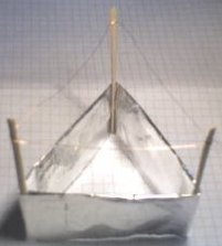
Using a small amount of glue, attach three lightweight balsa wood supports, and stick the two short edges of the foil together to form a triangle.
Loop a thin wire around the supports so that it is a few centimeters from the foil, and leave a long wire for connection to the power supply.
Connect another long wire to the foil, in a position away from the other trailing wire.
Flying the Lifter
The voltage required to power the lifter will depend upon its size but it is usually above 10kV. By moving the top corona wire closer to the foil, more thrust can be produced. If it is too close arcs will jump between the electrodes, causing it not to fly.
Place the thruster on an insulating surface (a table), and away from any metal objects.
Attach the two wires to the table so that the thruster can hover, whilst being held down by the wires.
Making a HV DC power supply for the lifter
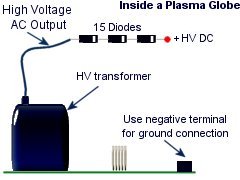
 For a tiny Lifter the output of a plasma globe PSU and a HV diode can be used, but for a larger device a larger transformer may be needed.
The picture on the left is of the inside of the plasma globe, and you can make the output of this DC by connecting it to a HV diode.
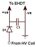
For larger lifters, a simple adjustable supply can be made by driving an high voltage coil with a power pulse modulator and then rectifying the output with a high voltage diode and capacitor as shown here. The diode D1 should be rated for high voltage such as 20kV, 100mA as to withstand current pulses from accidental shorts. The capacitor C1 should also be rated for 20kV. The capacitor is not essential but it can help improve performance and add some protection for the diode. The capacitance can be any value, but bigger is better.
The pulse modulator allows you to vary the output voltage very easily so that you can get more control over the performance of the lifter.


Put together the power supply using the power pulse modulator, ignition coil, hv diode and capacitor as shown in the circuit diagram. However when powered up I’m getting no discernible thrust, is there something in the set-up I should check for?
When working you will hear a noticeable hissing sound coming from the thin wire. If there is no hissing, fix the wire closer to the foil. The gap should be as close as possible without it arcing over. Also set the frequency fairly high when driving the coil. Should be a high pitch sound rather than buzzing.
Set the frequency to a high pitched whine (I see why now, too low and there’s lots of arcing across the diode) but still no thrust or hissing noise from the emitter wire. I found it needed to be 1mm or less before arcing would occur. Is their something I’m missing or not taking into consideration?
What diode are you using? How thin is the top wire? Spacing should be larger. More like 2cm. Send us a photo of your setup.
Diode is your 30kv 100mA, wire is 0.25mm, capacitor is your 35kV 1nF. Where would you like me to send the images?
Needs to be DC.
You could use a voltage doubler circuit to both convert it to DC and to double the voltage.
I was wondering if a neon sign switching transformer thing can be used for such a device..they ussually run at about 15 kv and i think thats AC…does the lifter require DC or is AC ok..If it can be used can they be wired in series to double the voltage?
Thanks in Advance
I tried using the very thin an lightweight metallized film from inside some polypropylene audio capacitors. The problem I found was that the metal would erode away from where wire was connected. I think this was due to it being connected at one point causing high current in a small area. With a better connection method, it might work better but I never got around to trying it.
Without an iron coil, the transformer you mention would not be very efficient.
You could probably send quite a lot of power by microwaves although it is not likely to be practical, or cost effective. I think the weight of any conversion hardware would be quite high. maybe with future nano-material technology, something better could be done.
I saw a remark above asking about using something other that aluminum foil. This got me thinking about the progress that has been made using tin chloride or (gulp) palladium chloride (choke, cough) to “electrolessly” plate plastic. I was wondering if something like metallized polyester film would do the job. 2nd question. It seems to me that nonmetallized poly-film used with copper foil could be used to make a transformer. Once such a transformer was made would it be lighter than an “off the shelf” flyback or the like. 3rd question. How much current can be reasonably be received from a high-power microwave transmitter? If the step-up transformer could be carried on board and receive wireless energy (resonating wireless power transmission also comes to mind) then perhaps it is indeed possible to accomplish something useful after all here. Sorry for so many questions. Looks like its math time. Thanks in advance for your time 🙂
You need to use very thin wire and just attach with a small amount of tape.
How do we connect the other long wire to the aluminium foil?
Not sure I believe that. Please post some pictures or video.
We built our own large EHD thruster and it could lift its own power supply and another 87KG have you any tips on how to make the thruster more effective so it can lift more weight?
Is there not a way to use this system on a plane?
It seems as though it would be cheap and easy to manage.
Of course, it would have to be far larger than this.

Ernesto Dizon
What energy it that then?
Oh yeah, rubber bands!!..
no matter what new energy form comes, or some new inventions;goverment would not honor it,because if these something for nothing motors,comes out;the goverment will lose billions upon billions of oil dollars,and so is the international goverments,OIL ;IS THE ALMIGHTY GOD OF DOLLARS!Australia has an invention:no gas or batteries,so is Japan,United States,england,all have,inventions that needs no batteries or gas,the CULPRIT IS GOVERMENT.LET THE WORLD HAVE THIS NEW ENERGY
ALIENBLUESTAR
The plasma ball PSU steps its input voltage (12V) up to thousands of volts.
You need thousands of volts DC for an EHD lifter to work
How do I use a power supply, as this is a learning curve for me. I get the use of a plasma ball cpu, but mine is only 15 volts! Will this be enough?
Thanks
The mains will provide way more than enough power for lifter experiments unless you are planning to lift something like a car!
The simplest way is to use a voltage multiplier to step up the mains.
Formula available here
Hey im currently buideing quite a descent power supply at ruffly 50kv DC
but quite low ampige since i am going from mains is that anoth to power a descent sized one and if not could u sugest a power supply design that would give alot more power i was thinking of makeing a much larger one useing 3 of them attached to gether and my final question is there a formula u could give me to find the thrust of givin size voltage and current.
thanks
ok thanks for answering my questions.
i now got some money t spend and gonna tinker with some of this stuff ill share iny thing new with you.
i dont know how i found this site but im happy i did this is a great site
No, a stun gun is a low current source of AC pulses. I know of noone building a lifter that also lifts its own power supply so far. Some people have augmented them using helium filled ballons to counteract the weight of the PSU.
The most lightweigt PSU I have used was made by removing the globe from a plasma globe and placing a HV diode or rectifier arrangement on the output so that it gives about 15kV DC (depending on size of original plasma globe). This will only give enough current to fly the tinyest of EHDT like shown in the video.
so would it be possable to hock up a stun gun to one im asking because i whant to have a light waight power source.and by the way you have a great website
The resistance of the material is not significant. Aluminum is used because it is relatively lightweight.
does it have to use aluminum couldnt somthing else work better like copper.
copper is a much better conducter
No. Electrostatic generators do not generate enough current for an EHDT.
There are many different ways to make and power a thruster. Google the term ‘lifter’ to find many examples.
well could an Wimshurst machine power an EHD machine.it creats HV and if spun fast enough it can creat high curent.and thier most be some more ways to desine an EHD to creat more power and to be more effient than the cunfiguation that u have up thier.
and if an Wimshurst machine cant power it than wut else can power on of this other than wut u have posted.
Thanks, RM. By the way, gr8 site!
A VDG does not provide enough current to power an EHDT.
More current or voltage makes more thrust upt to certain limits. Too much and energy is just wasted.
Attatching multiple units together is an effective way.
is it possalbe to power one with a van de grff and if it is how much power can you put in a ehd truster.will it generat more turst with more volts (and i mean more volts like 5 million volts)and more watts.
Yes, It is better to also place a 10M resistor in parallel with each diode too if make a diode string.
wud it work to put a bunch of ur 8kv diodes that r in ur shop in series or in parralel 2 charge a 30kv capasitor?
Into those pins. You will have to determine which two input pins work best yourself.
Oh. I apoligize.
But where does the power go in?
The pins are normally in a semicircle on the underside so they would normally fin to a PCB.
Pictures must be JPEGS ONLY 200kb MAXIMUM FILE SIZE.
Meet this spec or it will not accept your image
sorry. didn’t work. here:
I found a pickture of a transformer much like mine. Here it is (hopefully this picture comes out right):
I found a flyback transformer in an old computer, but I can’t find the input wires or pins. Do you think you could tell me where I can find them?
Something else that might help is that I know I found it on your site somewhere, but I’m not sure where.
Thanks!!
I couldn’t say
I am trying to build the flyback driver shown below, but I don’t think the feedback coil is working. One of the times I hitched up the battery, I got one spark, but it didn’t keep going. Do you have any ideas of what is wrong with the feedback coil?
thanks!
Oh. well, that makes it easier. thanks!
No, The diodes are built into the device.
ok. so the current is already DC, but I still need a high voltage diode at the end of the red wire, right?
The large red wire is usually used to supply DC to the front of the CRT screen. I would assume the tripler part is a separate circuit to this.
I found a flyback transformer in an old, color TV. It has a tripler built into it already, but the wires of the tripler are just sticking out. would the high voltage from the large red wire be DC already, or would the other wires coming out of the tripler have to be attached to something?
thank you very much.
It would be destroyed
what will happen if you use a regular (1000v) diode? ex. 1n4007
The rectified output of an ignition coil will be enough for a small lightweight EHDT.
would it be possible to power an EHD thruster using the rectified output of an ignition coil? Or does the power have to be doubled or tripled?
Just start with something small like 70mm wide by 40mm high for each foil side. The output of the transformer used needs to be rectified (converted to DC) using high voltage diodes. This is simple for normal transformers but this would not work for a Tesla coil because of the high frequency and voltage.
Hey firstly thanks for the great website.
Could you give me some dimensions, my transformer is a 10kv 25-30mA or alternately i have a flyback, which would you reconmend.
Have they ever tried to use a small tesla coil as power source or would this just be over kill.
Your propulsion systems would work as an alternative for today’s vehicles. With fuel prices on the rise, EHD can change the way we use vehicle propulsion. Your materials are even easy to construct.
If your propulsion systems were used more, we would save a lot of money.
Alex McCown, that is not correct. The output from the transformer in a plasma globe is high frequency AC.
The transformers in CRT screens give a DC output because they usually have a built in voltage doubler.
the output of that kind of flyback is dc already only the disk shaped ones are ac
There is more information available at the link below.
ElectroHydroDynamic Propulsion
did anybody ever establish the efficiency of the motor?