DIY Air Quality Meter & Emissions Tester
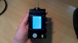
This little project shows how a simple hand held meter can be made for testing for air pollutants such as smoke and dust. It is based on the Sharp GP2Y1010AU0F sensor which measures light reflected from airborne particulates passing through the sensor. It is very similar in operation to the popular GP2Y0A21YK0F from Sharp which is used for measuring distance using reflected infrared light.
This project came about as we were looking for a simple way of measuring car exhaust emissions. Searching online for other DIY Car Emission Testers did not bring up much, so we decided to create this device and share it here. There is lots of scope for improvement on this project, even in just some more advanced code for more functionality.
 What’s Inside?

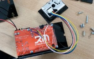
Inside the box is the GP2Y1010AU0F sensor, a small fan, and our PDI-1 which is a simple Arduino based controller with an integrated LCD screen. The code provided should work on any compatible Arduino device such as a Nano, or Arduino Pro Mini. The advantage of the PDI-1 is simply that it already has a display, speaker, buttons, and a rotary encoder built in.
The outer enclosure is made from laser cut acrylic. If you have acress to a laser, you cam make use of the box design file provided. You might want to tweak the design a little as it did not leave much space inside for a battery. The 9V PP3 battery we used did not really give a good service life.
To get the reading, the microcontroller sends a pulse to the sensor. The sensor then takes a measurement and outputs an analogue voltage proportional to the amount of pollution detected. For a stable reading, we take multiple readings 10ms apart and then take an average value. The code then converts this value to be displayed on a graph.
Making use of the built in rotary encoder, it has been set up so that turning it adjust the scale on the graph allowing you to sort of zoom in for more precision on small changes. A single press of the encoder button will switch the graph from a bar chart, to a line graph.
 Using The Meter to Test Car Emissions
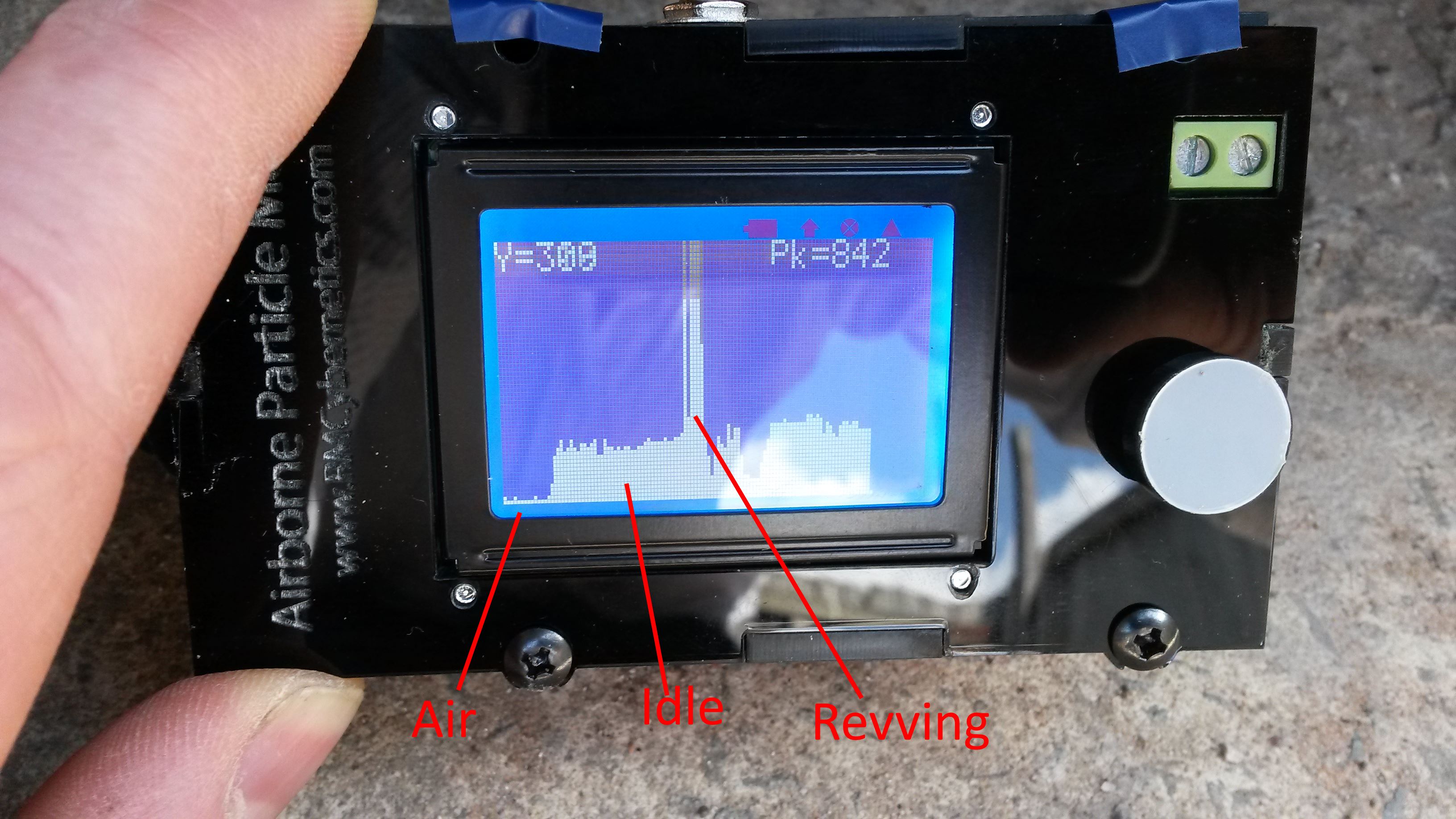
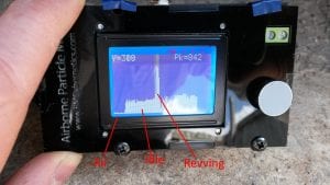
For a good reading the sensor needs a continuous flow of air through it. To achieve this a small 40mm fan was mounted inside the box which blew air out of the underside. This created negative pressure in the box allowing the air from outside to be drawn in through the sensor. On the outside of the box a common 8mm barb pipe fitting was added which in part helps to prevent outside light interfering with the sensor and also allows for a silicone hose to be easily fitted. To take the measurements the free end of the silicone pipe was simply put into the car exhaust while observing the screen. In the image here you can see the difference in readings for clean air, the car idling, and when the engine is revved.
The reading given is currently just a number from the analogue input. To improve this project, the system could be calibrated to give an actual particle density value. However for our needs, a simple relative reading was all that was needed.
The code for this project is available here. If you have any suggestions for improvements or have your own examples, we would love to hear from you. Please post your comments using the form below.


I’m a bit of a beginner. Is there a circuit diagram for this that I could look at?
You folks are great
Hi Pomme, We don’t have a diagram available, though you only need to use a single analogue input on an Arduino or PDI-1
This is a fascinating project but unfortunately I can’t afford the PDI-1. Is there a possibility that you could supply the circuit/connections for an Arduino?
Hi Peter, You can see the connections to Arduino ports in the beginning of the code.
// PORT DEFINITIONS
#define AD_VAL A1
#define LED_PWR 10
#define ENCODER_A 2
#define ENCODER_B 3
#define ENCODER_SW 8
If not using an encoder for adjusting like in the PDI-1, then you basically just need an analogue input connection.
Thankyou !