 A DIY Tesla Coil Tuner
By Terry Fritz
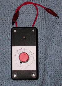
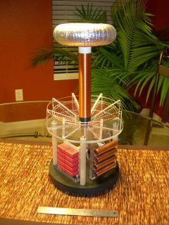
The Tesla Coil Tuner (TCT) is a simple and low cost signal source that can be used to find the resonant frequencies of the primary and secondary circuits of Tesla coils. It uses simple commonly available parts. It can be assembled in a few hours with minimal electronic skills. The cost of all the parts is about .
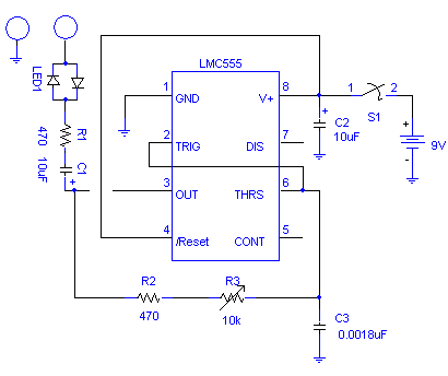
The TCT is simply a LMC555 IC square wave generator. An audio taper pot and a 2% polypropylene timing capacitor control the 50% duty cycle oscillator’s frequency.
A bi-color LED in series with the output senses the current being drawn and a frequency dial indicates the frequency setting.
| Qty | Parts |
| 2 | Sets red/black alligator clips |
| 1 | Large Control Knob |
| 1 | Bi-Colour LED |
| 2 | 10uF 16v tantalum capacitors |
| 1 | LMC555 CMOS IC timer chip |
| 1 | 8 pin IC socket |
| 2 | 470 ohm 1/2 watt resistors |
| 1 | 10K Audio taper pot with switch |
| 1 | Plastic Box |
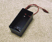
| 1 | Battery Clip |
| 1 | Battery Holder |
| 1 | Prototype Board |
Assembly:
There are many ways to put the TCT together and it will work fine. For those less familiar with assembling things like this, I will describe how I did it.
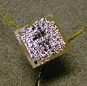
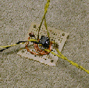
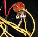
I selected the plastic cover and located two points on the cover. The first was two inches from the bottom and the other one inch from the top. I drilled a 1/4 inch hole at the bottom mark and enlarged it a bit to fit the 10k pot. I then snapped the little tab off the pot with pliers and mounted the pot with the 2.25 x 2.25 inch scale under the nut. I then installed the knob using the off position for alignment. I connected a 470 ohm resistor to the center leg of the pot. I drilled a 3/16 hole at the top mark and was able to force the bi-color led into it. I added a bit of epoxy to hold it in place. I also epoxied the battery holder in the bottom half of the box. I drilled two 9/64 inch holes for two 8 inch lengths of wire to act as test leads in the bottom of the box. I tied and epoxied the leads to the box and installed alligator clips to the ends.
 I used two other alligator clips to make a 6 inch jumper to short the spark gap for primary testing.
Circuit: Snap the two circuit boards in half and solder the 8 pin socket in the center of one. Following the schematic, solder the components to the circuit boards noting that S1, R2, R3, LED1, and the battery are mounted off the board. Use hookup wire to make the needed connections and bridge the pads with solder where needed. I put leads on the board for parts off the board.
Finish wiring the top and bottom of the box together following the schematic. See the picture for how the pot leads and switch are wired.
Install the battery and assemble the box top with the four screws.
 |
 |
 |
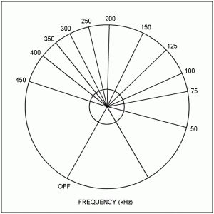 Calibration:
The provided scale will be fairly close. However, if you have a frequency counter or voltmeter with that function, you can calibrate your own scale
Operation:
The TCT is very easy to use for primary and secondary frequency measurements. Obviously, these test should be done will all power removed from the coil and all capacitors completely discharged! The procedures follow:
Insure all power is removed from the coil and all the capacitors are completely discharged!
Testing the TCT: To tests the TCT’s operation, connect the two test leads together. The LED should light and remain lit through the entire frequency range. Replace the battery if the light is dim.
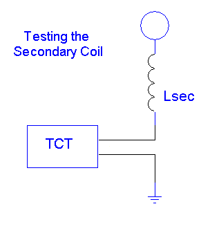 Secondary Fo: To test the secondary’s fundamental frequency, simply connect the TCT between the ground and the base wire from the secondary as shown below. Slowly turn the frequency through the range until the brightest spot is found. The lowest and brightest frequency spot is the fundamental. You may see the dimmer 3rd harmonic at ~3 x Fo. It is probably best to test the secondary frequency on the coil in the actual configuration since the secondary frequency is sensitive to the surrounding objects.
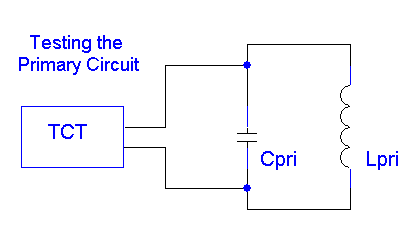 Primary Fo: To test the primary circuit’s frequency, simply connect the TCT across the primary cap and short the spark gap with the jumper. Slowly turn the frequency through the range until the dimmest spot is found and read the frequency on the dial. You may want to remove the secondary coil to prevent the secondary from affecting this test.


Hi I made this a lot of time ago, but back then I was using low power on the primary of my coil, so yes, it didn’t work. Now I made a 1600w 13.8kV transformer, 100mA. It already worked. So now I got the tuner and it already worked really well finding the secondary ressonance. Something around 154-156kHz Still have to tune the primary, thanks!
Hi so what one have to do exactly to tune just measure both coils and put them in same frequency?
Thanks
Yes, use a smaller value for C3 so it tests at higher frequency. For the resistor, try using a 1M pot and adjust it until the LEDs just go off. Then try adjusting frequency to see if you get a response.
What value should the resistor be between the topload and ground?I’m working on a small coil about 600 turns around a 3cm diameter paperroll.
https://www.youtube.com/watch?v=AYF9R7dWloU
I cannot get this circuit to work.I’ve tried two 102 capacitors in parallel then one 102 capacitor -half the capacitance- and nothing happens.Should I use a smaller C3 value the coil being so small?
Thanks RMCyb. Yes when I connect the leads both two leds light; cause I did two leds back to back.
Good idea to add a resistor the thing is that I have a broken freq meter 🙁 so I would not now the freq.
To test your circuit, connect the test leads together and the LED should light up. Also if your coil is quite small it may not pull enough current to light the LED. In this case connect a resistor between the topload and ground.
Hi I’ve built this tuner but leds not lighting. To inform you my secondary coil is bifilar and has 120uh.
Thanks
There are 2 LEDs as the current needs to flow in both directions. You can if you prefer, just replace one of them with an ordinary diode.
hello everyone!
I would like to ask, about the circuit, that this is indicator led, now this is one led or two.
One for led have 2 leg, this is led link I do not understand.
How to wire led to this formula?
Why are show two leds?
Thank you in advance for your help
Regards Peter
Sorry no, but the diagrams are clear enough.
Your pictures are so small. Do you have links to any better quality images?
Yes. Pretty much any capacitor within ratings will be OK
does the 1.8nf capacitor have to be polyester? and is a dip type tantalum capacitor okay to use?
Yes. C1 allows the AC ringing in the coil.
Does it matter if I eliminate C1?
There will be AC becasue of the coil ringing. This is why the two opposite LED’s are used. You could use a DC meter in series with a diode, then another diode or LED parallel with those. This way the meter would measure the current in one direction while it would just flow through the diode in the other direction.
i built this tuner. i am looking to modify it a little. i would like to put an analog DC milliamp meter in place of the LED. i can figure that part out, but im wondering if i need a DC meter or AC meter. im assuming a DC meter because it is actually pulsed square wave DC and not AC because it doesnt go below zero volts. it should work, because the frequency will be high enough that the meter wont have time to fluctuate and will peak at the resonant frequency. i am just looking for some input, advice, verification or opinions from you about this or what you think.
The resonant pint is often quite sharp. For more precision you will need to use a multi turn potentiometer.
Alternatively you can add a lower value pot in series with the other (R3). For example; if you add a 1k pot, you can use it to make the fine adjustments with 10 times more precision than the other pot.
hi,i have biult this tuner and it all seems to be working fine but there is a slight problem,my 10k pot seems to be a little too sensitive at around 300khz range and its hard to get the leds to stay lit,it allways flicks past the point that you want it to be at,iv added a 10 turn geared knob to the 10k pot to try to tame it a little but its still not perfect,is there anyway to make it a little less sensitive?.
thankyou.
Yes, the 955 should work fine.
Will a 955 timer be ok, I was ordering a bunch of stuff, when I searched for the 555, the 955 showed up on the list as well, I bought the wrong ones, ima noob
LED1 in the schematic shows two diodes. Just connect the LED’s like that.
The LED’s will not light unless enough current flows between the test leads. If you connect he test leads together, the LED’s should illuminate.
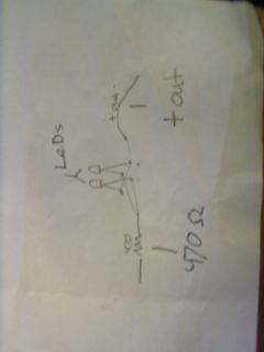
i build the circuit with all the right stuff except the bi-color led, i used to leds this is how i wired it…i connected one + and one – from each led to the 470 ohm resistor then connected the other + and – lead to the output there not lighting up(test leads)do i need diodes? sorry for the bad drawing….
Yes, just use two LED’s.
can i use 2 leds instead of a bi-color led. Do i wire then opposite? +- then -+ ? and do i need diodes. do you have a schematic for your TC tuner for sale the one with 2 green leds.
-thanks
Yes, they will change in brightness. If they are not changing, you need to change the capacitor for a different frequency range. 3kHz is very low for a TC, especially a small one. You should be looking in the range of hundreds of kHz.
I got the TCT doing a range of 131.1 hz to 2.86 khz. Both my primary and secondary read at 129hz on the lowest setting of the TCT. My main concern is the LEDs. Are they suppose to brighten and dim when I’m adjusting the TCT when its feeding the primary or secondary? Because the LEDs stay full on the whole time.
How can I tell when the whole circuit is perfectly tuned?
Yes. This chip should work fine. There must be some problem with your wiring.
Question. I have an NE555P chip. will that work in place of the LMC555 chip? If so. For some reason mine will not turn on or do anything. I have checked every thing like 6 times. still nothing. If you could help that would be great.
That would be fine, it just needs to be rated for the supply voltage to the circuit.
How important is the voltage rating on the timing cap
would it work if it was 1.8nf at 100v
Alexander L.,
You could possibly make the measurement across your capacitive load as it would have some resonant frequency when combined with the inductors in the circuit. Remember though, this circuit wont give you a frequency, you would still need an oscilloscope to measure that.
Fabio R,
The losses in the capacitor greatly effects the Q factor. The resistance could mean that when you use the tuner, you just see the LEDs lit all the time.
I’m working on the same diagram posted by Alexander and I have the same question too.
It should work with pulsed frequency on the primary and secondary frequency by the way transformer is connected have a double pulse thus is twice primary f. the secondary is connected in parallel or series with the water capacitor which have a low resistance. Would it resonate even with the losses of the capacitor? Does the losses on the capacitor affect the Q factor?
And I would like to know if your lc resonator would be useful for this application too.
I would have a question about impedance transformation too. Which impedance is considered in the transformation? 1 the internal resistance of the driver circuit? or 1 + 2 the reactance of primary or 1+2+3 it depends on the load???? My circuit is a car battery and a mosfet irfz44n wich have 17.5 mOhm Rds(on). What is my internal resistance?
Thank you very much
Hello,
I am working with a water fuel cell that works most effeciently when pulsed at resonant freq (ReF). High voltage and low amperage are the most effecient ingrediants, though it should work with what i am using ie, a PWM @ 12V and up to 20amps.The ReF changes as the water level changes. Would this tuner be useful in identifying the ReF if so How? It is a design by Stan Meyer. I have attached a circuit diagram in case you are unfamiliar with the device.
That looks nicely put together. Be sure to post a pic when u get it working.
From what you describe, I would think it is not resonating in the range of frequencies on your TCT. Try just the second or 3rd turn (closest to secondary) as this would have a significantly higher frequency than the outer turns.
Also make sure your spark gap is shorted, the secondary is removed, and you may need to disconnect your transformer.
I recently built your TC tuner to tune a new 1 inch dia. Tesla Coil. Connecting to the primary I do not observe any dim spots from the LEDs, just dim during the first 1/4 turn of the potentiometer, and then full on for the rest. I do however observe the multiple bright spots when connected to the secondary, so I believe the circuit is functioning correctly. Should I change C3 to another value so that I can find the resonance of the primary LC circuit; or, is the point just before LEDs stay full on the resonance point? I’ve tried changing the contact point on the primary (the last two turns are exposed) but see no difference using this tuner.
It should be in the hundreds of kHz I would excpect.
One more question: what is a good range of frequencies for the secondary coil for a 4 in. diameter coil? Mine said something like 80 Hz. Does this sound normal? I always assumed it would be much higher, like in the kilohertz range.
thanks again!
Sincerely,
Der Strom
Yes Parallel
So do you mean I hook it up directly between the TCT probes (positive to negative) so it is basically in parallel with the part being tested? Or is it in series?
Sorry, I’m a little confused.
Thanks again!
-Der Strom
The frequency meter would connect between the test lads of the TCT.
Yes, the LED’s will light up proportionally to the current flowing between the test leads. If it is not lighting at all, it indicates that to little current is flowing. You could try increasing the frequency by using a smaller capacitor for C3.
If I have a frequency meter, how would I “connect” it while testing the frequency? I assume I should connect it between one of the output leads and the part of the tesla coil that that lead would usually be connected to. Is this right?
And one more problem: when I don’t connect the test leads to anything, the LEDs (I’m using two, facing opposite directions) go out. I assume this is right. But when I connect it to the secondary coil to test its frequency, the LEDs stay out throughout the entire testing range. Is this right?
thanks for your help, as always!
Der Strom.
The original version was called a “Dip Meter” It’s the basic idea of using an oscilator with a milliameter to monitor current draw and interchangable coils to cover the spectrum needed. long ago they were made with a vacume tube, (I made one once) then transistors took over. In use the coil was brought into close proximity coupling with the coil to be tested and the oscilator tuned through it’s range till the meter dipped, and that would be the resonant frequency of the tuned circuit. They were used most for the 0.5 to 30 MHz range. This one with a 555 for oscilator and LED instead of meter is a low frequency version. I will stick one together in the next couple days because I’m coming to where I need to do some low frequency coil tuning.
The part of the a TC you use this on is AC anyway so yes it will work for both setups.
Will this tuner work with an AC Tesla Coil setup?
shouldnt you be using a TTL timer IC and not a CMOS?? TTL’s are more hardy and can tolerate more abuse than a CMOS devices. TTL’s are cheaper too…
so how do you tune a tesla coil then im confused. p.s i made the tuner
No, these values would not be equal for a TC. The shape and size of the inductors are different so you would not excpect the same result unless L1 and L2 were wound on the same shape former with the same spacing and wire diameter.
lol sorry
n1 = primary number of turns
L1 = primary inducatnace
n2 = secondary turns
L2 = secondary inductance
when you divide n1 by l1 it should = n2 ,l2
tomson,
Yes, electrolyitis are fine
justin,
Not sure what you are talking about. I assume N1 and N2 refer to numbers of turns, but without any reference for context the formula is useless. If you want a good answer your question needs to contain more detail.
is N1 Over L1 = tO N2 Over L2
primary LC = to seconadry / toroid in frequency wise?
for the tesla tuner at the top would it matter what type of capacitor you use for example could i use a electrolight capacitor rather than the ones posted provided they have the same microfard rating?
I don’t know what your equation for c=r/9E9 is about at all.
You can find info on toroid capacitance here
hello
i decided to do some studying instead of asking dumb questions lol but im confused about this one equation for universal capacitance and hoped you could help
c[f]=r[m] divided by 9×10 power of 9
i know how to do the equation but how is this relevant to the seconadry windings, it only meassures the capacitance ,do you know any equations that would be relevant to both the secondary and the toroidal capacitance?
by this i mean from the seconadry equations how do you know what surface area to use as a toroid. i hope my question isnt confusing thanks
Push/Pull should be equal. There are two diodes (or bi-color LED) used so that current can flow in both directions through the probes. This is useful because when each square wave pulse hits the LC circuit it is allowed to ring.
The brightness of the LED’s indicates how much current is being drawn by the load (your LC circuit). If a lot of reactance is produced by the load then the LED’s will be dimmer.
To make the reading more accurate you could use a comparator. This could be set up to compare a reference voltage to the voltage you measured on the LED’s. For example; if measuring an LC series circuit the comparator could be set so that it lights another LED only when the measured voltage is high enough.
One more question when hooking my multimeter up to each lead of the led in ac mode lowest voltage is dimmest and highest voltage is brightest right?(it seems to be) thanks abunch for your help. Lloyd Romero
are we looking for an equal current draw and pull in the led so that both parts of the led light. if so with the use of a digital auto polar multimeter when voltage is a zero than there is equal draw and pull. but im just not sure i understand how the led read-out exactly works.
I have build my tuner with a 3 way switch to change out caps. and can reach freq. of 2 mhz according to my freq. counter. is there any way the make the tuner output more accurate right now im using the bicolor led. i have to wires with aligator clips coming off each of the led lights leads for expiremening. any ideas would greatly help. thanks
You can use any type of capacitor dielectric.
does the cap have to be a polypropylene i am using a .001uf ceramic-disc cap, seems to work.
The LED indicates how much current is flowing from your tuner. At resonance the reactance of your secondary will drop and allow current to flow.
If the applied fequency is not correct then the LED will not light. 555 timers come in a few flavours even thuogh they are all called a 555. Some work up to just 0.1 MHz, while others will go to 1 MHz and some even go to 2 MHz. Check the manufacturers datasheet for the 555 you have to see if it it goes high enough.
It could also be that your coil/topload combo is too small for the TCT. It will work well for large coils but smaller coils can resonate well above 1 MHz which would mean that the LED would not light up.
im not sure if my device is quit working but when connected to the primary the led lights up but when connected to the secondary nothing im not sure if my toriod is not at resonace capacitance or if the circuit is just lighting the led with no square wave and i have no ossiliscope to test could you suggest a reason for this problem?
If the secondary coil is centre tapped for RF ground then you would test it in the same way. Otherwise you would have to use one of the ends instead.
Dear RMC,I have three small and medium size BIPOLAR TCs with equal toploads on each end of the secondary.
They are functioning OK. However, I want to find resonant frequencies by means of DIV TC Tuner. Could you please advise how to connect the Tuner to test bipolar TC. Thank you.
The TCT finds the resonant frequency of the primary or secondary circuits. This means either the combined inductance and cpacitance (LC) of the primary, or the LC of the secondary.
Yes, the simplest way to use this is to measure the f of the secondary coil and then try to adjust your secondary turns or capacitance until it also resonates at this frequency.
If the resistance is really 471 than this should make no real difference but I think you are reading the codes wrong. 471 ohms is not a standard value. The colours should read Yellow(4), Purple(7), Brown(x10).
with the tc tuner dose it matter if you replace the 470 ohm resistor with 471 ohm would this make a difference this is the colour band if im wrong plz correct me yellow ,purple,brown
thank you very much but to sum up what you are saying dose this mean we are finding resonance individualy primary and individualy primary? i thought it worked by finding resonace of the secondary find the number on the dial keep dial still on that number and make your way through the primary to the dimmest spot so that both resonaces join .joel
The tuning instructions are in the article. Read the last 2 paragraphs.
Secondary coil and topload – brightes spot is resonant.
Primary coil and cap – dimmest spot is resonant.
I’m not sure that there is a ‘standard’ copper wire. This circuit uses very low currents so quite thin wires will be fine. I would guess that the standard you refer to is something around the thickness of the individual wires in a network or telephone cable. This thickness is fine.
forgive me for asking a stupid question but with the tc tuner would the dimmest spot be resonance for both primary and secondary or is ther mathamatical equasions involved if so please explain in laimen terms. also would standard copper wire low resistance be good to use on the prototyping board? joel
The output from the 555 timer is a sequence of dc pulses. It basically allows the connected LC circuit (tesla coil) to ring properly with AC.
Where does the DC come from that needs to be blocked?
Its is there for DC blocking, but it will probably round the edges too.
Is the purpose of C1 to convert the square wave into a sine wave or what? Thanks.
Yes you could, but you would need to account for the bipolar nature of the signal if your meter is a DC one.
Would it be possible to replace the LED with a digital ammeter for more accurate tuning?
Maybe you could try changing the value of the timing capacitor (C3). This would allow you to tune the TCT over a different range of frequencies. The pot doen’t give you a linear adjustment, so a different cap may help you adjust from a more central position.
I got the TCT working, checked it out by loose coupling to my friends Transciever and there appears to be a signal out … and at very accurate calibration. BUT when I try it on a coil
( 22mm dia 740mm long, 0.27 mm enamelled wire, dia . approx 260 turns.
I calculate =377 micro Henry about = 223 kHz
1.344 pF ) I only get bright LED’s all the time, they only dim at about 30khz which is near the end of the pot travel.
Any ideal what I am doing wrong… this is testing just the secondary coil with out any cap connected
The test leads are indicated on the diagram by the two circles. One is simply connected to ground (negative battery terminal), the other is connected to the LEDs.
Pins 5 and 7 do not connect to anything.
I am not too sure where the test leads connect on the T.C. TESTER circuit is it pin 7 and pin 5?
Tesla Tuning problem..
The tuner works very well.My coil is tuned correctly for the first time..Spark length was Maximum 17 Inches. The tuner proved that my primary coil was far from right, it would not tune any where near the secondary. Rebuilt primary, tuned, Powered up and Max Spark is now 25 Inches..A very useful tool.
A frequency counter is a very good partner for the tuner,quite a few Digital Volt Meters now have frequency counters.
Also useful for checking Bat Detector Frequencies, sonic ears etc..
Not sure about that one. Are you measuring the output at the TCT probes, or directly from the output pin of the 555?
This device was designed by Terry Fritz of hot-streamer.com. His contact email listed on his site is “terry[at]hot-streamer[dot]com”
OOPs. I had tied the chip output to C1. I fixed this and checked everything else again. Now I can’t get anything to work. The circuit is now correct…C3 is 1nf. I changed the 555 and same problem exists. Tested LED…fine. There is no oscillation…output steady at about 8v. Any ideas? Thanks.
Hello. I have built the unit..output of 96kc to 330kc. The LED has a very dim output throughout the range and then no LED wide open. What LED are you using? Have any idea why the LED cuts off? Thanks.
I assume you mean replace it with two LED’s wired in opposite directions, which would work just fine.
If you used just diodes there would be no indicator showing tuning.
Increasing the capacitance by a factor of ten will not exactly reduce the frequencies by a factor of 10 but it may be close enough. This is because the rate at which the capacitor is charged and discharges depends on other factors too.
Will a pair of diodes wired in oposite directions substitute well for the bi-colored diode?
Will increasing the capacitor by a factor of 10 reduce the frequencies by a factor of 10?
One method for increasing the frequency range of a 555 circuit is to add a switch which allows you to select your timing capacitor. An example of this can be seen on the DIY PWM Signal Generator page. The 555 timer may generate frequencies of up to 1MHz, but there can often be instabilities in the signal at the high end.
The discharge pin is not hooked up as the circuit is configured to respond to the inductive or LC nature of the coils. The discharging of the timing capacitor depends upon the nature of the curcuit you are ‘tuning’ rather than it being directly discharged by the 555 timer.
I have found that using two Radio Shack 0.001 uf (1 nf) capacitors in parrallel works pretty well. Their value is actually more like 0.0009 uf or 0.9something nf apiece. Your values may vary. Putting them in parallel gets you really close 1.8 nf. BTW: I measured it with a LCR meter to check this.
Also… 2 questions:
1) How do I increase the frequency range? Do I make the capacitor smaller. I measured that mine had a range of 20 kHz to 415 kHz. I would like it to be more in the range of 100 kHz to 1.5 MHz or so. I have been working with rather small coils and they resonate at higher frequencies.
2) Is this an Astable 555 Circuit? If it is why is the discharge pin not hooked up?
Thanks in advance,
Chris F.
The value of this component does not really have to be exact. Use the closest value (capacitance) you have available and it should work fine. The only real difference will be in the accuracy of the printout for the frequency dial. To use this device it is not essential to know the exact frequency ayway.
This capacitor is charged and discharged by the 555 timer to produce the output frequencies. If you replace it with a larger capacitance then your output frequencies will be lower. Replace it with a smaller capacitance and the frequency will be higher.
The 1.8nf 50v capacitor seems to be a problem for sourcing here. Do you have an alternative?