A Tiny Homemade Square Wave Signal Generator (‘Dead Bug’ Style)
 This page shows you how to make a super simple square wave signal generator. The circuit below uses a 555 timer chip, a capacitor, and some resistors to generate a variable frequency, variable pulse width square wave. The term ‘dead bug’ refers to the way that the finished circuit resembles a dead insect. This is because the solder connections are made directly to the components and there are legs sticking out making it look much more messy than the diagram below.
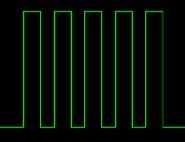
This is a very basic circuit and therefore does not produce an ideal square wave over the full frequency range. The pulse width or duty cycle can only be varied by a small amount, and doing so also effects the frequency output.
If you want to try a more advanced and more accurate version see the DIY Signal Generator II
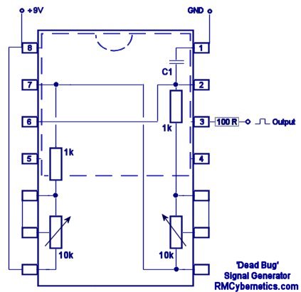
This diagram shows how the circuit can be wired without the need for any circuit board. A 14 pin IC socket is used to hold the main circuit so the 555 chip and the two pots can be simply plugged in. The total parts list is shown below.
14 pin IC Socket
NE555N Timer IC
1k Resistors x2
10k Variable Resistor/ Potentiometer x2
Capacitor selection for C1
If you want to switch loads like coils, motors and lights, our range of Cyber Circuits are for you!
The diagram represents a view from below and is not to scale. The circuit may be a little tricky to solder, but its about as simple as you can get for a signal generator.
This circuit can be used in the DIY Tesla Coil project as part of the Ignition Coil Driver
The value of the capacitor C1 will determine the range of frequencies produced. Somewhere around 0.1 to 0.01 microfarads should be adequate for mid range audio frequencies.


help..
555 timers usually pop with in 2seconds..when 12v 7amps power is supplied even after adding a voltage regulator..plz help me what is the reason for it n what should i do to stop pop of NE555
Thanks
Hehe, thanks! Over 4500 messages now 😀
You deserve a medal for extreme patience , RMC.
555 timers usually pop from voltage spikes in ignition coil circuits. You need to add a voltage regulator or TVS to protect it
This seems to have died, however i’ll post my experiances. I just built this circuit with a 555 timer signal supply with 1 ignition coil. It works very well, however the 555 keeps burning out after 10 seconds or so of running. I need to get CMOS timers and put series resistors in. noob, I can take a picture of my breadboard and send it to you if you want.
Hi.
If someone could put a picture of this circuit on a breadboard i would be really grateful.
Thanks if you can 🙂
Hi. Great site, thank you 🙂
I would like to add a 2N3055 to this circuit to pulse a coil.
1. Is this possible ?
2. What would go from the 555 to the 3055, just the output pin-3 ?
Thank you 🙂
This can only operate up to about 15V. For 24V operation you should use a 12V regulator to supply the circuit. For switching a relay you will also need a small transistor to amplify the current for the relay coil.
I need to generate a 24v dc signal at a frequency of 27hz. What is the output signal/voltage of this circuit and can I use this to operate a relay???
Yes. You would need to calculate the resistor capacitor combination for your specific timing needs.
Can this circuit be used to control a pair of lcd shutter glasses? I need them to “open” for periods of about 10ms at about 4Hz.
No. You need a totally different circuit.
Can i use this circuit as a receiver circuit for rf remote control? and what should i alter to achieve this
Brian,
No, the 100 ohm resistor on the output is used for limiting current. If yo are driving a low impedance load, maybe you should increase the resistance of this.
If the pinout and voltage spec is the same, you can use it
Do you need to use a NE555N timer or can you use other timers of the NE555 family? I could only find a NE555P at my local RadioShack but it doesn’t seem to be working.
Also, do we need anything to limit the current going into the chip? I don’t get why the chip burnt out so quickly.
Mirrored? Look at the pin numbers and also where it says “The diagram represents a view from below”
Hi RMC,
Could you label the NE555N pin connections? According to my STMicroelectronics NE555N chip data sheet, the circuit wiring above is mirrored what it should be (it connects +9V to the gnd pin, gnd to the Vcc pin and so on.. see image). I didn’t catch this in time and burnt my chip out. Just don’t want this to happen to someone else.
Thanks!
Continuum,
There is no -9V connection really. Voltages are relative. If you say the negative terminal is -9V then the positive one would be 0V.
Typically the negative connection is used as 0V or ground while the positive is +9V.
Steve ford,
It can but you will need to use resistors to make a voltage divider on the 555’s output so it will match the LM1949’s input requirements.
The 555 will work from 12V, but then the output would also be 0 to a bit less than 12V.
Can this circuit be used to drive an injector driver such as a LM1949? i will need to be running 5 x LM1949’s powering 5 injectors simultaneously. Also can this circuit be powered off 12v? if so what will the output voltage be?
Thanks
Steve
Hey RMC, I was wondering. When using a 9V battery how do i establish a ground? Is it simply using the -9V end as ground?
Induction heaters are driven with a square wave driver. The resonant inductor-capacitor circuit oscillates in a sine wave when the square wave input is the right frequency.
Hi RMC is there a diagram for a sine wave gen. I want to make a low wattage induction heater the coil uses high frequency AC voltage can this be simulated with a sine gen and a power amp on an ignition coil to drive the induction coil. thanks Paul
Yes
can this circuit be used as an RF transmitter , i mean to use it to drive a single switching transistor ?
Becasue of lazyness I suppose 🙂 Most versions of a 555 will work when the reset pin is left unconnected, but it is probably better if you connect it to V+
I have tried many different circuits similar to this, I’ve success and the circuits have failed miserably. In this circuit, pin 4 is disconnected to the positive rail. Why?
What if you want a sine wave with a constant amplitude over a varying frequency range like a sweep tone generator
If you have vertical mount minature presets, you can just pluc them into the IC socket. if not, you will need to add leads to the pins and insert them into the socket.
how do you connect the potentiometer?
This value just refers to the amount of power it can handle. The power in this circuit is tiny so it does not matter what value you use.
What Wattage resistor (I wan’t aware resistors had watts. the ones i’ve found are either 2, 7, 10 watts) would be suitable for the 1k resistors of the ‘dead bug’ signal generator, the 100 ohm resistor of the ‘dead bug’, the 10k resistor of the driver cricuit, and the 100 ohm resistor of the driver circuit?
And once the ‘dead bug’ circuit is complete, how do the potentiometers operate? (what do they do, or what should I do to them).
cheers.
The 100R refers to a 100 ohm resistor used to limit the current flowing from the signal output.
Yes 1k is 1000 ohms resistor.
Any potentiometer witht he same resistance value will work. The one used here is a linear type.
Yes 9V is +ve battery terminal. -ve terminal goes to GND
Could you help me with a few queries on the’Dead bug’ signal generator;
> What is the 100R next to the output of this circuit?
> Does a 1k resistor refer to a 1000 ohm resistor (1 k ohm)?
> Can any potentiometer be used as a variable resistor, or are they different components?
> Does the 9v input come from the positive battery terminal? If so, where is the negative battery terminal connected to?
many thanks.
This circuit will not drive any coils by its self. It only provides signal. Maybe you should look at the ignition coil driver.
It worked well and flashed at approx 2hz. Without a cap, i just upped the resitance/s which I figured from a handy 555 timer program.
Thing is, when I connected it to my coil the 555 gave up.
I had connected a cap and resistor as a snubber across the coil. also a zener 5W 15volt from the irf740 mosfet to ground.
Do you know what went wrong?
Thanks again
Ben
Most caps are non polarized (there is no specific + or -). One which have larger capacity tend to be polarized and the pins are clearly marked. Typically these are electrolytic or tantalum capacitors. The -ve leg of such a capacitor would connect to GND in this circuit.
Capacitors larger than 100nF will allow you to see the output if connected to an LED.
RMC, fantastic pages here and a huge amount of patience for people on a steep learning curve like me!
Could C1 be changed to a value that would allow an IRF740 to switch a LED for testing. i.e. so you can see it flicker?
Also, feel really stupid here, which way round do I mount C1 and how do I tell the + side of the cap?
Many thanks
ben
A similar rated one might be TIP142 100V 10A. A MOSFET type IRF740 400V 10A would also work
dear rmc is there a transistor other than the 2n3055 that would work in the self resonation circuit for a flyback? high speed switching and heavy current loadig.
ohh thank goodness i thought that i was so bad at electronics that every time i tryed the same circuit it never worked now i know why thank you now i wish i had of tryed dc insead of building the same circuit over 26 times spending $200 for a $ 4 circuit thankyou
Yes it would. You need to use a proper DC supply or a battery.
dear rmc i have made quite a few square wave circuits in my time but no have worked. my power supply is that of a car battery charger 12v . i have noticed that it oscilates a little as most chargers do. would this affect my square wave circuits indering their performance? please reply soon as im hanging off the end of my chair to know thank you, sincerly geneotype.
It would provide an adequate signal, but a large transistor would be needed for switching the power.
You can see examples on the ignition coil driver page or the power pulse controller page.
would this circuit be suitable for a auto transformer or car coil?