A DIY Robot
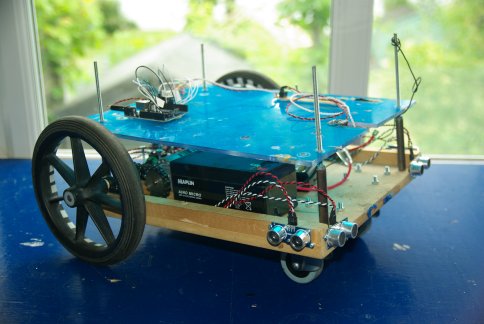
This Arduino robot is built using the chassis from our old DIY Robot Project, but we have replaced the sensors and the electronics to use more modern parts. We intend to develop this robot as far as possible so there will be many updates to this which will be added to the article. Code and schematics are provided so we hope that if you use them you can post your project and any contributions here.
This project will be a continuation of the original MIRC and will keep the key concept of using ‘animal like’ responses and fuzzy algorithms while keeping logical “If/Then” actions to a minimum. The intention is that this approach will make the system more flexible and adaptable.
Obstacle Avoider
 This article will cover the initial stage of creating a system so that the robot will be able to get around and avoid obstacles. This requires a basic system for motor control, and also for reading and interpreting sensor information. The processing for this will be done using an Arduino Uno which is an open source electronics prototyping platform using an ATmega328 micro-controller. This has the advantage of being simple to program and interface with. There are also many code libraries available on the Internet which people have shared for making programming of common tasks even more simple.
Sensors
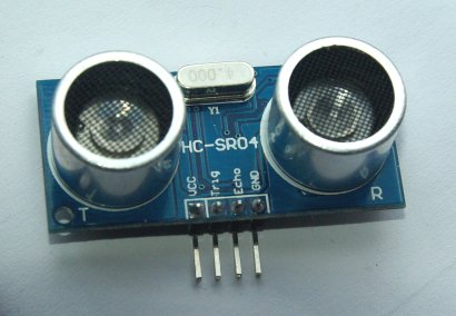
Starting with just four ultrasonic distance sensors the robot should be able to detect large obstacles such as walls, furniture, and people. The sensors are arranged on the front of the robot so that it can detect obstacles as it approaches them.
The sensors used are the HC-SR04 ultrasonic rangefinders. They were chosen due to the low cost and ease of use. They can connect directly to the Arduino without the need for any other electronics. These are a great alternative to the PING))) sensors from Parallax which cost around 5 times more. The HC-SR04 requires two digital channels on the Arduino which is its main disadvantage over the more expensive PING))) sensors which need only one. The SR04 sensors, when triggered, will emit a series of ultrasonic pulses and measure the time taken for the sound to reflect back. From this they will output a pulse with a duration proportional to that time. Knowing the speed of sound, it just takes some simple calculation to work out the distance of the obstacle from which the sound was reflected. There are a number of Arduino libraries for the SR04 sensors, but the one used here is an excellent one by Tim Eckel and is called NewPing. Using this library means that it just takes one line of code (after the setup) to get the distance in cm (or inches if you prefer) from any of the sensors. They will accurately return a distance reading from 2cm to 500cm with an accuracy of around 0.3cm. You can also limit the maximum distance if you do not need 5m and this will speed up measurement times as there is no need to wait for the return echo.
Motors and Drive System
The two back wheels are directly driven by some gear motors, that can turn independently so that steering is achieved by turning the wheels at different rates. The front wheels are just a pair of casters which move freely.
 The chassis for this robot is quite large and heavy because we intend to add much more to it later. This weight meant that the wheels should not be directly connected to the gearbox output shaft on the motor. Instead they were mounted on separate axles with a couple of bearings so that the weight is taken by them instead of the motor. If you want to replicate this part of the project, it could be done with a tiny robot as the Arduino and sensors are very small and lightweight.
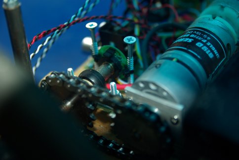 To the end of each axle is a rotary encoder. It was originally fitted to the motors shaft, but at a count of 64 pulses per turn, and a gearbox of 148:1, we felt that 9472 pulses per turn of the wheel was an unnecessary overhead for the small processor. The encoders were instead placed directly on the axle so that it would give 64 pulses per wheel rotation.
Any time the robot moves the wheel may slip slightly on the floor so this is an important consideration when using encoders to track the movement of the robot. To counter this problem, later versions will combine data from an accelerometer, magnetometer (compass), and the distance measurements with the encoder data to more precisely work out where the robot is and is moving.
Power and Wiring
 The robot is powered by two 12V SLA batteries. One battery supplies power to the control electronics, while the other is used to power the actuators (motors). By having separate batteries, the high drain from the motor will not interfere with the accuracy of the sensors and control system. The battery for the control electronics feeds into a pair of voltage regulators (5V and 12V) so that the control electronics and sensors have the right voltage levels sent to them.
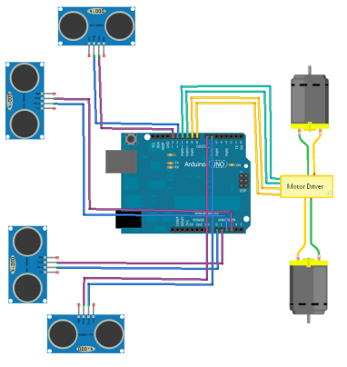
The power to the motors is controlled using a pair of LMD1800T H-Bridge drivers. They take 2 PWM signals from the Arduino, and two more for the direction of each motor. They also have an output for indicating current flow in each motor. This can be useful for detecting if a wheel is stuck as the current would increase significantly.
The diagram on the right shows the connections to the Arduino I/O ports. Connections for power are not shown for simplicity.
Source Code – Fuzzy Algorithms
The Arduino can be programmed in C# which is a simple and flexible language. In the first part of the code there are declarations for libraries, variables and constants that will be used later in the program. For this program the NewPing library is included so that the SR04 ultrasonic sensors are simple to use.
The main loop function will just be used to call other functions in the correct sequence. These functions are simply ReadSensors, AvoidWalls, SetMotors, and SerialDebug.
ReadSensors will ping all the sensors and store the measured distances in a set of variables. Later this function might also get the values from other sensors on the robot.
AvoidWalls is where all the numbers from the sensor readings are processed and the speeds for each motor are calculated. The algorithms used are known as ‘fuzzy logic’ because the relationship between the sensors and motors is continuously variable rather than any on/off conditions.
For example; To avoid a wall on the left of the robot, the speed of the right motor should decrease relative to the left motor, as it gets closer to the wall. This would have the effect of turning the robot away. The algorithms calculate an ‘urge’ to turn left or right, then these valuse are applied to the motor speeds.
newMotorSPD_L = basicVelocity + urgMotor_L + (urgTurn_R/4) – (urgTurn_L/2) + 60;
newMotorSPD_R = basicVelocity + urgMotor_R + (urgTurn_L/4) – (urgTurn_R/2) + 60;
Download the source code to see more.
When programmed in this way, the robot will simply stay still unless something tells it otherwise. If an object approaches it, then it will retreat from that object and try to maintain a distance from it. If you want the robot to drive around, then the value of basicVelocity should be set to a value above zero. This will give it a constant ‘urge’ to move forward while the algorithms will keep it away from obstacles. However, when moving like this, the robot can come to an equilibrium state when it is facing a corner. This is where the sensor values cancel out the basicVelocity and the robot will cease to move unless the obstacle changes.
SetMotors uses the speed values calculate in AvoidWalls to set the motor direction and PWM output values. It can also be used to accelerate the motors so that a soft start/stop is achieved. The rate of acceleration is determined by the value of urgFatigue which will add delays to the changing of the motor speed if this number is greater than 0. It is named urgFatigue as increasing this value will make the robot more sluggish and slow to respond. It should be noted that when accelerating the motors, delays are used and the sensor values are not being processed.
This system of urges and automatic obstacle avoidance will form the basis of a more advanced robot. Using serial communication, the urges will be manipulated by an external program running on a PC. The software on the PC will deal with more advanced processing such as mapping and route planning but will not directly control the motors. Instead it will simply calculate the relevant urges for the robot to move and then send them to the Arduino.
If you have any comments, questions, or suggestions, please add them using the button below.


I’ve built a replica of your DIY Robot II which I’m using as the basis of a simple lawnmower.
I’m having a problem with the code in the respect of when the robot meets an object at the front of the vehicle, the robot stops and waits, forever. I’ve looked at the code and tried several different things including altering the basicVelocity setting but it doesn’t make any difference. I wondered if you could point me in the right direction (pardon the pun) with the code.
Any advice would be massively appreciated.
Scott
By comparing the measured speed and the intended speed, then including a measurement for time, a fuzzy algorithm could be made to get it out of the corner. The result would be something like an increased urge to turn left that is proportional to the length of time it is stuck. It may also be necessary to create a counter to count the attempts at getting out of the corner, and to increase the urge to turn in proportion to the number of attempts. This would prevent it from oscillating repeatedly in a corner. It might be much simpler to use IF/THEN type of coding, but this is contrary to what we are trying to do with it. This also forms the beginnings of the robot having a reference of time, events, sequences which will progress in later developments. Currently we are working on some PC software that will allow the robot to map its sensor data to an image. This will allow it to begin mapping the environment and eventually plotting a path to a destination while avoiding objects in memory. We will release an executable and source code (Visual Studio C++ project and Arduino code) when we have something ready for use.
How will you prevent the equilibrium problem in the corners? What else will you be adding to it next?