Coils
Coils
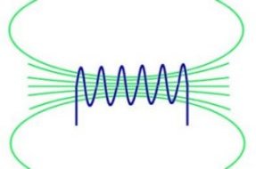 A wire coil can be used to concentrate magnetic flux in a controlled area. The most common form of coil, known as a solenoid, can be a single loop of wire or multiple turns in series. The diagram on the left represents the magnetic field in a typical solenoid.
By winding multiple turns in the same direction its possible to increase the total magnetic field strength. A typical solenoid posses a property known as inductance which creates a resistance to the change of flow of current in the wire.
Helmholtz Coils
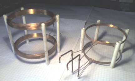 This type of coil is used to generate a uniform magnetic field. Two coils are held parallel to each other at a distance less than their diameter . The field between the coils should be quite uniform, providing the strength of the overall field is high enough.
Helmholtz coils are commonly used for scientific tests which require controlled field conditions. They can be used for canceling the earths magnetic field or for testing the effectiveness of magnetic shielding for example.
They are also useful for measuring the magnetic properties of materials.
Bifilar Coils (with opposing windings)
 This type of coil, when powered does not create an external magnetic field. Its construction is similar to that of a normal solenoid, but each turn of the coil carries the current in opposite directions. The opposing currents create an overall canceling effect, thus no major external field is produced. A bifilar coil will produce almost no inductance to a changing, or AC current. This makes them useful for creating non-inductive wire wound resistors.
Scalar theory suggests that this type of coil produces ‘Scalar Waves‘, but the standard model of physics does not accept scalar waves as a valid theory. Bifilar coils are often mentioned along side so called Over unity, or free energy devices.
This is because the vacuum fluctuations, or ‘Zero Point Energy‘ are like canceled vibrations with a massive energy density, and are seen as scalar waves by some. Standard scientific theory tells us that the entropy (disorder) of a closed system always increases and therefore no useful energy could be extracted from the vacuum.
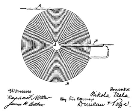
The image above show a patent by Nikola Tesla for a type of bifilar coil. In this configuration the two wires are wound the same way and then connected in series so that the current flows in the same direction. This allows the magnetic field to combine to produce a larger overall field.
XYZ Coils
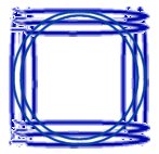 These are simply solenoids, or Helmholtz coils arranged to point in all three dimensions. They are also used for scientific tests or experiments involving controlled field conditions. Some theoretical teleportation experiments mention the use of XYZ coils for creating some kind of ‘fourth dimensional’ field When this field is coupled to an object and then driven at some fundamental resonant frequency, the object could be made to move in the fourth dimension. An observer would see the object disappear and then re-appear in a different location.
Penning Trap – Plasma Containment
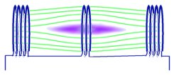 A Penning trap is a set of electromagnets or coils that will create a controlled non-uniform magnetic field. The diagram on the left shows how the magnetic field is slightly less intense in the centre of the trap. This ‘bubble’ in the field lines is where anon neutral plasma can be contained. A non neutral plasma is simply a plasma that has an overall positive or negative charge, such as a collection of electrons. A charged ‘particle’ such as an electron would require an accelerating force to move it across the magnetic field lines. Without this external force the electrons in a penning trap will tend to spiral back and forth within the area of weakest field. The converging field lines at each end act like a ‘magnetic mirror’ allowing the plasma to remain contained.
Next Page: Other Dimensions
Previous Page: Particles?
19 Comments
Leave a Reply
You must be logged in to post a comment.
In relation to Penning Trap – Plasma Containment.
Would this plasma , in your opinion , be able to restrict the flow of air into a container if it was used to replace the containers lid?
is yes what would the largest plasma containment that could be made?
Actually, there is no mistake. The main description is describing bifilar coils with opposing windings, but below the image it describes the coil shown.
Hello,
I just stumbled uppon your article and Bifilar Coils description is incorrect – This coil acts as 2 coils in parraler just like 2 wires 1 by another. And because the electrons and holes goes into same direction on both wires (look at the image carefully, there is no outter entrance->center->center->outer exit!), we get same thing as 2 magnets connected with opposite poles to each other (extended and amplified magnet).
Cheers!
Well I assume this field is oscillating, otherwise there is no way to get energy from it. I’m not sure I really understand what you are asking. Perhaps you are looking for a core material with a high magnetic permeability.
Dear Sir(s),
What might be the best way to maximize the “collection” or reception perhaps, of planar magnetic field into a magnetized core (such that whatever magnetic flux could most efficiently be converted to a voltage and current)?
Perhaps an analogous way to picture the situation would be an optical lens focusing plane waves of light (where the plane waves are from infinity and much wider than the lens or mirror system used to focus what could practically be available to it). Would it be via an antenna on the collection end or end(s)?
I suppose it could, but the magnetic field strength needed would be huge. The amount of plasma it could contain would be proportional to the field strength.
Is the Penning trap capable of containing/making pressurized plasma? If so, is there a way to measure how much plasma the trap can contain/make?
The inductance will be different.
50 bifilar turns is equivalent to 100 single turns since there are 2 wires – so – what is the difference in Tesla’s coil versus a standard coil using the same core?
Dear sir ,Thank you for your reply,even if some is somewhat vague. I have since found the answer to my question of optimum coil length/magnet length from an article by ‘Nightstar’ which is 1:1. That being a concrete positive answer, I shall act upon. The End
I don’t know what the optimum coil length would be. It is likely to depend on a combination of factors such as magnet size, Gauss, shape, velocity, coil inductance, and load impedance.
By winding direction I mean clockwise or anti-clockwise around the tube. If this direction remains the same then it does not matter about layers, odd or even.
If a magnet goes through two coils you would get two identical pulses. Being side by side (2 magnets) or one after the other (1 magnet) only affects when you get the pulses. The proximity and juxtaposition of the coils will affect the mutual inductance.
Not new but it’s novel. Two plastic CD sleeves (like envelopes),one has one third of teaspoon of homebrewed iron filings,seal the sleeve with selotape.Second sleeve filled with white paper and sealed.Place second sleeve under first,and magnet under that. Lovely patterns,rotating the two sleeves evens out the filings,more card spacers above the magnet varies the patterns.
Dear Sir, Thank you very much for your reply, although some answers seem incomplete, I’ll explain:
Your answer to (2) How much longer, is there an optimum, like 1½ x magnet length or ??.
Tilting would be more correct, one way then the other.( across the hand)
You answer to (5) Is acceptable if you agree to question 3 & 4 and I will clarify:
Questions 3&4 If one winds on tube from left to right to complete 1st length of coil, then doubles back on that winding, winding now right to left to make second layer and to continue as required. Does it matter if it is an odd or even no.of layers? Where the connection leads are, or
possible cancellation.
Your answers to 6&7 Also appears to be incomplete, maybe the way I offered the questions, to clarify:
Consider a tube held at 45 degrees,
1st instance: single magnet slides down through single coil, one cycle completed.
2nd instance: single magnet slides down through two spaced coils, two cycles completed.
3rd instance: two magnets slide down (separate) through two spaced coils, four cycles completed At this stage, all is hypothetical, but are 2nd & 3rd feasible? Your opinions will be appreciated. Regards Jack .
I can’t answer everything in detail as it would take significant time and effort. I can give you some pointers so to aid you in calculating the answers yourself.
1)No. The windings should just be as close as practically possible to the magnet because thi is where flux density is highest.
2) The longer the coil, the more flux is captured by it, but the field strength does decrease exponentially with increasing distance from the magnet. Therefore it would be best to be longer than the magnet. You should also consider the practical situation of how easy it would be to shake it.
3)No. Windings should always be in the same direction otherwise they cancel eachother out. The more energy you extract from the passing magnet, the more the magnet will be slowed down. This would mean the mass of the magnet would affect how easy it would be to shake it effectivley.
5)Multiple layers would be more efficient due to more flux being captred at once.
6)Double compare to what? A single coil? It would not quite be double at that distance because both couls would be picking up something wherever the magnet is.
7)same as above.
The important thing to note is the basic fundamental fomulae for calulating energy and how these are relevant to your application.
a) The more energy you extract from a moving magnet, the more force is needed for it to keep it moving.
b) force(N) = mass(g) x acceleration(m/s2 c) work done(j) = force(N) x distance moved(m)
Dear Sir, Came across your page, looking for ‘optimum’ winding construction details for coils for use in a hand generator, kinetic movement of magnet through coil, (shaker torch principle). I have looked at Faraday info’ and the like, but none seem to present answers to my questions. Hoping you may offer some guide lines. Starting with a known factor: the magnet is 10mm x 30mm cylindrical, 12,800 gauss, with this I hope to produce the most voltage/current possible, without the whole assembly becoming to cumbersome, beyond a single hand held unit. So here are the questions:
(1) Is the optimum shape of a cylindrical coil dictated by PI, 3.14(etc) X Diameter or the size of the magnet?
(2) Is maximum energy received from the coil when it is the same length of the magnet, or more ?
(3) Would more energy be available from the coil if it had multiple winding layers, wound in alternating directions?
(4) If the answer to (3) is yes, would the quantity of layers be odd no’s, so the start and finish of the total inductance will be at opposite ends of the coil?
(5) So far I have considered only wide single layer coils, but would there be any advantage in using a narrow high stacked coil, say just a quarter width of the magnet, just random filled with wire until full,?
(6) Would I receive double performance if a single magnet passed through two identical coils, spaced apart by the length of the magnet, or more? (Each coil having separate rectification, the outputs summing to the same storage.)
(7) Taking no’7 a stage further, could two magnets (suitably spaced) passing through two coils obtain X4 performance?
Kindest regards Jack Grogan VIA maureengrogan@yail.com
Can you give me a link to the write up on this not just some random links and a world ends lecture.
Please prevent explosion of the planet.
First study the Tachyonator for example.
See http://www.iris.edu for current earth quakes.
The shifting of the tectonic plates, fault lines and 23.45 degree inclination where possibly caused by time travelers that tried to change our past that caused multiple time-lines that stress and endanger our reality, our time-line and our planet.
I hope the Terrawatts and knowledge is used to stabilizer our planet in stead of to create the man made earth quakes (see http://weatherwars.info for seismograms that prove the earth quakes where man made and information about scalar and the Genius Tesla).
In 2025 the world will run out of cancer oil at the present rate of consumption so the electrolitic capacitor, the http://waterpoweredcar.com car and planes flying on hydrogen and other forms of free energy and wireless energy will be used.
To people (ab)using the above information at the moment: please use a frequency generator because one of these coils amplifies the energy with a factor 250000 Volt, can let our planet explode when handled improperly and when used in combination with 220 or 110 Volt would cause a black out, fire and cancer in all people exposed to the field.
Usually frequencies like 15 Hertz are used with a so called succor punch which has a mobius coil wrapped quartz crystal. My experience is that these do not block their scalar surveillance satellite attacks so please let me know if you know a way to block their scalar wave attacks.
These scalar waves pass through all types of matter and do not loose their power when travelling so it is very important only healing frequencies are used in combination with this active succor punch instrument.
See http://doctorno.wordpress.com for more information and if you want to mail me to exchange information about scalar and zero point energy generators. My goal is blocking their scalar attacks.
Safety first.
It would depend on how you were trying to apply the force. The calculations can get a little technical because there are several factors to consider.
If you are just wanting to make an electromagnet, the best way is a simple solenoid wound on a ferrous (iron) core. Placing iron in the core of a solenoid will increase the field strength. Different materials will also help or hinder the flux. You could try winding a solenoid on a hollow plastic tube, then inserting different materials into the tube to see how they affect things.
The magnetic flux produced by the coil is proportional to the current, the number of turns, and the density of the turns. Increasing any of these will increase the field strength.
If you add significantly more turns the resistance of the coil will be larger. This would mean that for the same battery or voltage, the current would be less (see ohms law).
To overcome the increase in resistance you could use thicker wire, but then this will obviously mean that the number of turns you can fit in a given space is reduced. There is always a compromise somewhere.
Another way to increase the current without increasing the voltage is to cool the coil down. you can see how temperature effects resistance of a coil in this experiment.
Which electromagnet gives off the most force