M.I.R.C.
Project MIRC
(Mechanized Interface for Robots & Computers)
Project MIRC is a mechanized interface for robots and computers. This robotic system was developed as a final year project for Bradford University in 2003 / 2004. The Idea was to demonstrate how fuzzy programming could be used to allow a robot to adapt to its surroundings.
Abstract
“According to the Handbook of Industrial Robotics, the number of robots in the United States almost doubled in the 1990s, with robots doing an increasing number of diverse jobs” [1]. It is predicted that robot technology will become more available for everyday household and small business functions. This will create a need for innovative ways of integrating robots into increasingly technology dependent lives. The modular system developed as a result of this project, is described throughout as MIRC, which stands for Mechanised Interface for Robots and Computers – it is not a robot in itself, but a mechanism for interfacing robotic hardware with standard computer systems.
This project aimed to develop a modular system (MIRC) for interfacing already commonly available hardware for conducting household or industrial tasks, with standard computers. Ultimately, it was designed to link to an already established infrastructure to develop new and more effective ways of utilising it.
The MIRC could ultimately enable the technology of the PC to become mobile, thus minimising the need to carry out mundane or repetitive activities and to enable long distance completion of tasks. In the proposed approach, the MIRC was operated by command from a laptop which had been programmed using fuzzy algorithms to carry out basic object avoidance and wheel tracking. By using fuzzy algorithms rather than the more standard IF/THEN statements currently used in programming the MIRC has increased flexibility and potential for adaptation for a range of uses.
Currently most advanced robots are custom made for a particular task and expensive to produce. Other robots are designed simplistically as toys or gadgets, and as such are mass produced and relatively cheap to produce. The MIRC which has been produced as a result of this project combines these factors by using mass produced components to create a technically advanced robotic system which has the additional capacity for customisation, giving endless flexibility. Ultimately it could allow the consumer to purchase a MIRC and then to create a robot custom built for their needs from standard components without the need for extensive knowledge of robotics or expensive outlay.
1.2 Rationale
This project was chosen because this area of the technological industry is not being fully exploited. Whilst researching the availability of robots for adaptation to be used in the home, only one type of labour saving robot was found to be available. This is the autonomous vacuum cleaner [2]. It is a small robot that will map out the floor of a house and then vacuum it without the need for human interaction (apart from emptying the bag). This was an important technological breakthrough, but a cost of around £1000 per unit, makes it outside the price range of the average consumer. The high cost of such robots is mainly due to the costs of developing its custom computer hardware and software.
1.3 Current position
Moore’s law states that computing power doubles every 18 months [3]. Although according to Dylan Tweny, this is probably not true [4], computer technology is currently at a point where processing power on a small sized pc is large enough to deal with extensive real time data e.g. web cam image processing. These computers are now cheaply manufactured and available in most homes. People are already customising their personal computers to their own needs. The logical next step would appear to be extending or combining technologies to create a whole new product, which had potential for a new way of conducting tasks currently conducted by people. This gave rise to the idea for the MIRC.
PCs today are much faster than they used to be. So much so, that the average computer has enough processing power to adequately analyse sensor data such as stereo video images in real time. Due to the PCs huge variety of applications and its popularity across the world it seemed clear that a robot could be based on this technology. This would allow for USB devices and component upgrades to come from the same sources as normal PC equipment. The same manufacturers could also make the products, allowing it to reach world markets very quickly.
A fully constructed model could be capable of many things. If many different manufacturers created USB and FireWire upgrades, the robots could have a huge range of functions. Devices like robot arms, vacuum cleaners, paint sprayers, even robotic legs could be added simply by attaching them in the correct place and installing the software. Wireless networking would enable robots to communicate with each other from almost anywhere and the owner to control them all via the internet.
1.4 Literature review
In embarking on the project to create the MIRC it was necessary to conduct extensive research into both the current situation re the development of similar technologies and specific research into aspects necessary to design and build the MIRC.
There are surprisingly few PC based mobile robots in existence today. When searching the internet for PC controlled robots, mainly static workstations were discovered.
Arrick Robotics [5] sells various robotic products. Their Robotic Work cells can be joined with XYZ positioning tables to create the work cell of your preference.
Kuka Robotics [6] also sells PC controlled robots. These are large industrial robotic limbs that are fixed to the ground, used for welding and press-linking.
Another project found was called “Robotics Engineering Task Force” [7]. Here they were working on creating standard interchangeable robot parts so that industrial robots could be easily constructed. The idea of creating an ‘Industry Standard’ is progressive as it allows other manufacturers to create a wider range of devices and helps to boost the market. This indicates that if the MIRC were to be manufactured, standardised fittings for adding hardware or changing parts could be made.
Whilst conducting the literature review, it was surprising to find only two other projects similar to the MIRC. One is a project known as the ‘Open Automation Project’ [8]. This project bares a striking resemblance to project MIRC. This project not only involves a PC based robotic system, but it also uses some of the exact same electronics, such as sensors and the I2C BUS to communicate with them. The OAP aims to create a PC based mobile robot for the cost of a standard PC.
“The objective is to use readily available “off-the-shelf” low-cost consumer components where possible, and to design electronic subsystems where such components are either not readily available or are too expensive. In terms of affordability, the overall goal is to design a robot that can be made for around the price of a PC (US,500 to ,000 is the target, but the actual cost of building a robot can vary greatly depending on how many of the electromechanical components are made in your own workshop versus purchased pre-fabricated).” (ibid)
This is almost identical to the objectives of this project, but with one main difference. The Open Automation project (OAP) involves using a built in PC motherboard and processor to control all the hardware. The MIRC does not have any on board processing. It relies solely on the computer it is linked to. The first obvious advantage of this is the final cost of a finished MIRC would be greatly reduced. It is assumed that by the time the MIRC would be ready to be manufactured and sold, the majority of people will own some type of mobile computing device. This could be anything from a laptop or PDA to a modern mobile telephone. It is intended that any such devices could be used to control a MIRC depending on how much processor power was required. Standard PC motherboards could also be used as this would mean a better processor power to cost ratio could be achieved.
Another project is the ER1 [9]. This has actually reached the manufacturing stage and is on sale in America for 0. The ER1 makers have very similar aims to that of project MIRC. They also decided that by excluding the computer from the finished product the final cost can be dramatically reduced. The main differences between the ER1 and the MIRC is that the ER1 is specifically designed for use with a laptop where as the MIRC is intended for use with any type of computer. The ER1 needs to be trained using quite specific instructions whereas the MIRC will use more of a fuzzy learning method.
“’Training’ an ER1 requires the owner to use very simple ‘if/then’ logic, to be very literal with the poor machine” © 2004 MSNBC Interactive [9]
This ‘if/then’ type of training will enable a user to get the robot to perform tasks quite quickly after opening the box, but this also greatly limits what the robot is capable of doing. With the fuzzy learning approach proposed for the MIRC, it will take much longer to train a MIRC and it may be quite repetitive, but the end result would be much more effective. This is because it would be able to use what it has learned in being trained for one task, and apply it to other relevant tasks helping it to learn more quickly. Just like when training a dog for example.
1.4.1 Acquiring new skills
Having only brief training in electronics or mechanical engineering created the need for the author to gain some knowledge in this field. There is no shortage of information available on these subjects, therefore learning these new skills was quite productive. Some of the information on the mechanical hardware requirements was collected from a book named ‘The Robot Builders Bonanza’ [10]. This book contains basic plans and descriptions of mechanical systems involved in robot building. It also contains some information on linking sensors and motors to controllers such as the Leggo Mindstorms kits. This book provided most of the information needed to create the drive system.
Information on electronic components was found available in ‘The Forrest Mims Circuit Scrapbook’ [11]. This book provides various example circuits and descriptions of how all the components are working. This book particularly useful when linking the I/O ports of various pieces of hardware as it shows various ways of altering signals using electronic components.
Information on the various interfacing methods was harder to find. Most information was obtained from the web shops that sold them. The Information on USB interfacing was obtained from ‘PC Interfacing Using USB’ [12]. This book mainly contains details describing how to use the USB IO24 module to control motors and capture data.
1.4.2 Programming
Programming information was taken from various sources. For C++ programming ’Sams Teach Yourself Visual C++ 6 in 21 days’ [13] was very useful. This book contains simple step by step tutorials which teach the basics of using Visual C++. Although this book provided information on creating some programs in C++, It was unhelpful in understanding how to use it to control the hardware. To solve this, a Yahoo group [14] that had been set up for people needed information on the K8000 interface board proved useful. The K8000 Yahoo group was an invaluable resource throughout this project, one person in particular was Christian Allegre. He was able to advise me how to program the K8000 using C++ with Windows XP.
For QBASIC programming ‘Programming In QuickBasic’ [15] was invaluable. This book provides most of the information needed to create QBasic Programs used for controlling hardware.
1.5 Objectives
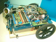
The aim of this project was to create a prototype MIRC to show how a PC based robot could be developed. The objective was to produce a basic model with four wheels, standard sensors and a web cam forming the centre around which an individual could create their own custom robot with extra USB devices.
It was intended that the structure of the robot should be simple to facilitate easy adaptation and upgrading. The housing was designed to create three distinct layers within the MIRC to separate elements of the robot, thus leaving room to add more devices and a laptop computer when complete. The bottom layer would be designed for battery housing and mechanical hardware, such as wheels and sprockets, the middle layer to contain the main interface electronics, and the top layer to be for the external devices.
The MIRC was developed over a period of eight months. Initially research was conducted into robotic control systems, pc interfaces, sensors and actuators. A K8000 interface board formed the basis of the project, as it allowed for the connection of analogue sensors and actuators to the pc. The PC was chosen rather than built in micro processor because it was far more powerful and customisable.
1.6 Limitations
The actual MIRC produced was limited by a variety of factors. Processing power of the laptop used (90MHz) limited the amount of data that could be captured and processed within a given time; laptop batteries were defective which meant that larger batteries had to be used which affected the overall weight and ultimately the manoeuvrability of the MIRC. Lack of modern ports such as USB stopped connection of modern hardware with a high data or bandwidth capability. Mechanical engineering knowledge and access to tools, materials and equipment were very limited which caused time delays and construction problems. It also added to costs due to the need to purchase tools. The authors’ knowledge of high level programming languages such as C++ was initially limited and meant time had to be spent learning the basics. A decision was made to use QBASIC as it is very easy to learn and it would run properly on the aging laptop used. Financing the project was also problematic. The author had to take on a part time job to cover some costs. Conveniently this job was in an electronics shop which staff discount was available on some of the required hardware.
2. Project Management
Project management was generally done on a step by step basis. This was because all the required parts could not be purchased together so that the costs were spread out over the entire project. This also meant that individual pieces of hardware were tested and developed as they arrived. The main influencing factor in choosing the hardware at the development stage was the cost. Finding the most effective parts within a limited budget proved very difficult. The software was developed along side the hardware as new parts were added to the MIRC. This makes describing construction chronologically very difficult. The table shown in Appendix A shows the progress made in comparison with the original plan.
2.1 Interfacing
The versatility of the PC in part comes from the variety of IO ports it is able to use. This allows it to connect to many different types of hardware, and with ever growing processor power the bandwidth capabilities of the ports grows too. The most important part of the MIRC was the sensors, so a good interface for these was essential. It needed to have the capability of capturing analogue and digital sensor data and also outputting in the same way.
This section describes the options available for interfacing a computer with robot hardware. Where appropriate it also gives an indication of strengths and weaknesses of the various components in relation to project development.
2.1.1 K8000
The K8000 [16] is a PC interface board which connects to the parallel port. This board consists of several analogue and digital I/O ports that are connected by a bus system known as the I2C BUS. The connected PC can communicate with the K8000 using RS232 data sent via the parallel port. This board formed the main interface between the computer and the sensors and actuators. This board can be controlled using RS232 data, giving it the possibility to connect it to almost any microcontroller. The K8000 can be used under Linux as someone has created drivers for it. An example of this is shown on the libK8000 house alarm website [17].
The K8000 is designed to run from a mains outlet, which is obviously not suitable for a mobile robot. To overcome this problem the transformers were removed and dc voltages were applied where the transformer output used to be. The small transformer was easily replaced by 6V from a lead acid battery, but the larger one required at least 15V. As the largest battery on the MIRC is 12V a step up inverter, normally meant for running a laptop in a car, was used.
2.1.2 I2C BUS
This is a commonly used bus system [18] for electronic devices such as televisions, but is now becoming quite common in the robotics field. This is mainly due to the large amount of hardware that is already available for use on an I2C bus. On web shops for robot hardware [19] there are various types of sensors that use the I2C BUS. These range from ultrasonic range finders to electronic compasses.
2.1.3 USB IO24
This device is simply a board with 24 digital i/o pins that can be individually set as an input or output [12]. This is done with software on the PC when the device is connected to the USB port. These pins can then be connected to different electronics such as analogue to digital converters. There are also many other versions of this device available [20], most of them are not much bigger than the USB plug its self. This was not implemented in the MIRC as the laptop used was not USB compatible.
2.1.4 Wireless Interfacing
A wireless interface would mean that the MIRC would not have to carry around any bulky computer hardware, as all the sensor data and instructions for the MIRC would be transmitted wirelessly between the MIRC and a desktop PC. Wireless interfacing could greatly reduce the size and weight of a MIRC based robot, but it also has it drawbacks. First of all the bandwidth of wireless connections is much more limited than when using wires. This is not really a problem for the majority of sensor data as it does not require a high data rate, but this does greatly limit the amount of more advanced hardware that could be used. USB2 data rates are much higher than currently available from standard wireless links. This means that good quality real time images could not be transmitted wirelessly without adding too much cost. Not only is bandwidth a problem but so is the transmitter range. A robot under wireless control would be limited to the area covered by the transmitters and could also be subject to interference which would effect both the range and the data rate.
2.2. Hardware
The MIRC consists of many different pieces of hardware working together. This section describes the various electronic systems that make up the MIRC and how they were constructed.
2.2.1 Sensors
Having to buy only the cheapest sensors was frustrating as they are the main factor that will affect MIRC performance. The first type of sensors needed was proximity detectors. The sensors chosen for this were simple photo reflective IR devices. These sensors consist of an infra red LED and phototransistor in a plastic case; they would output a voltage that was dependant on the amount of IR light hitting the detector. Using analogue sensors enabled development of fuzzy logic to control how the robot avoided objects. These sensors worked well at short range as long as there was no ambient sunlight. It wasn’t until the weather got sunnier that it was realised how much the sunlight would affect operation. Sunshine affected the photo reflective sensors outputs by increasing output to about ¾ of maximum. Adding sunshine sensor and adjusting the other sensor values relative to it stopped the sunshine from making the outputs go too high but it reduced the range so much that they were useless.
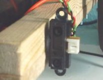 A much better type of sensor is the Sharp GPD-12 Infra red range finder. It is much larger in size than the photo reflective sensors but is much more accurate as it measures the angle of the reflected light as well as the intensity. On board signal processing then converts this to an analogue output voltage. The downside to this sensor is that it costs over £10. The GPD-12 is one in a range of infra red range finders by Sharp. They come with various output types and ranges.
One sensor on the MIRC is an ultrasonic proximity detector. This is the Velleman K3502 parking radar kit. This kit usually sounds a buzzer when an object passes a preset distance from the sensor. To connect this sensor to the K8000 the buzzer was removed and the buzzer output was connected to a digital input on the K8000. There was no need to alter the voltage or the buzzer output, as the K8000 can tolerate a wide range of voltages (5-20V DC).
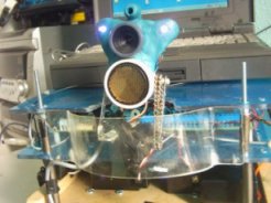 The head module on the MIRC contains several sensors, one of which is an ultrasonic range finder by Milford instruments [21]. This sensor uses the Polaroid transducer system, which has a single transducer for sending and receiving echoes. This is mounted on a servo for panning and is controlled by a board connected to the computers serial port. Another sensor in the head is a USB webcam of 640*480 pixels. Currently this has not been used in the project as the laptop being used does not support USB. With a more modern laptop this camera could be utilized for many functions, such as object recognition, motion tracking and remote avatar web conferencing.
2.2.2 Actuators
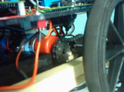 The main actuators of the MIRC are the two drive motors. Each motor drives one wheel independently. The original design involved using a four wheel drive system. Steering was done using he ‘tank drive’ method. This allows for a zero turning circle and therefore greater manoeuvrability in a small space. This method was found to be insufficient due to large amounts of slippage and torque requirements. The current method employs two large back drive wheels and castors at the front. The steering is done in the same way as the ‘tank drive’, but as the wheels are on the back the turning circle is increased to twice the length of the MIRC. The great reduction in slippage with this method meant that less torque was required and therefore better performance was achieved. The speed and direction of the motors can be controlled via the K8000 and H-Bridge driver board [22]. The motors are fitted with a 148:1 gear box to give greater torque, but this was still insufficient for the ‘tank drive’.
The other actuators are the pan and tilt servos for the head assembly. The panning servo is controlled by the same board that controls the Polaroid transducer range finder. The tilt servo is controlled by a separate board [21] which is capable of controlling up to 8 servos. This board is not currently connected due to the lack of ports on the laptop used in development.
2.2.3 Body
The body of the MIRC consists of three layers. The bottom layer is for the drive mechanics and batteries, the middle layer is for the interface electronics and the top layer for the computer and room for expansion. The base was initially made from an aluminium sheet with aluminium shelving brackets along the sides for strength. This eventually had to be changed as the original base did not prove sturdy once the heavy batteries were added. Rapid acceleration and turning caused the whole base to flex, which eventually caused the chains between the motors and wheels to slip, and one of the gearboxes to break. This was one of the main obstacles that was overcome as it slowed progress and wasted funds. The new base is made from a piece of thick MDF with wooden supports for the bearings, and performs much more effectively.
2.2.4 Multiplexer
The K8000 is limited to four analogue inputs. This problem was solved by creating a sensor multiplexer. This device was able to allow the computer to capture data from several sensors using a single analogue input on the K8000. To do this it was necessary to create a device that could switch eight digital outputs one at a time and be controlled by 1 digital input from K8000. This is very similar to ‘running lights’ where several LED’s run in sequence and start again. To keep the multiplexer small it was decided that a PIC microcontroller would be used, as this would greatly reduce the number of required components. Having had very little experience using PICs this activity proved a valuable learning experience. The chosen PIC was the 12F675 because of its small size (8 pin) and the low cost of the chip programmer. This PIC has only four digital outputs so these also needed to be multiplexed. The digital outputs when low can be used like a ground connection, allowing LEDs to be connected directly across two outputs (fig 1)
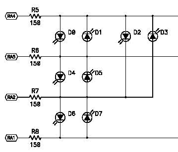
Figure 1. Multiplexing a PIC 12F675
With the previously mentioned setup each LED could be lit one at a time. The next step was to connect the PIC to transistors so that the output of 8 different sensors could be diverted to a single output. This was done by replacing the LEDs in figure 1 with Opto Transistor Isolators (OTI). These are basically an LED and a phototransistor in a sealed case. The OTIs were then connected to larger transistors in order to tolerate higher currents. Figure 2 is a simplified circuit diagram of the multiplexer. Resistors, capacitors, etc have been left out to make it easier to follow. The red and blue dots on the diagram represent connections to the sensors.
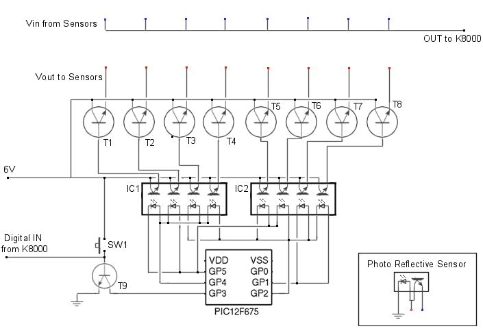
Figure 2. Custom made PIC based sensor multiplexer
When power is connected the first sensor in the array will be active. It would be as if it were connected directly to the analogue input of the K8000. When the signal from the digital output of the K8000 goes from low to high the power to the first sensor is disconnected and the next sensor is activated. This process repeats until the last sensor is activated and then it starts again from the beginning. This was housed in a plastic box and jack sockets added to allow easy connection and removal of sensors. The capturing of the sensor data and the software on the PIC is explained in the software section.
2.3 Software
The software currently being used to control the MIRC is written in QBASIC. This language is neither modern nor powerful, but it is relevant to the dated laptop used. At the beginning of the project it was difficult trying to get java programs to work adequately on the laptop. Finally it was realised that the laptops slow processor could not handle all the computation required by this platform independent code. Although QBASIC could not be used to produce an adequate final working program with a GUI, it was sufficient to control the majority of hardware. If a more modern computer had been available to work with better quality programs could have been produced and more advance hardware added. C++ was the preferred language but the editor and compiler were too complex for the laptop used. Editing on a PC and transferring compiled programs to the laptop was not practical due to it having faulty disk drives and communication ports.
2.3.1 Programming
 Various programs have been created to control different parts of the MIRC. The programs contain a large number of subroutines that can be called to perform a particular task. For example, StopLMotor is a subroutine used to stop the left motor. The instructions it contains tell the K8000 which IO ports to enable or disable.
Communication between the K8000 and the PC is done using serial RS232 data but the K8000 its self uses the I2C BUS to communicate with the various components. When purchased the K8000 comes with some example BASIC code that contains subroutines for the I2C communication. This was very useful as it meant that extensive serial communication subroutines did not have to be written. Once all the I2C subroutines had been collected together into one program it was possible to communicate with any part of the K8000 quite easily. The value of a sensor on an analogue input can be obtained by calling the subroutine ‘ReadADChannel(2)’. The number in brackets represents which port you wish to read from, in this case it can be from one to four, as there a four ‘AD’ channels. One of the first programs created (Appendix B) was used to display a visual representation of the voltage on an AD channel. The program simply moved a pixel horizontally across the screen at a set rate, and moved it vertically relative to the AD channel value. The result of this was a graph displaying how the voltage had changed over the past few seconds.
Communicating with the panning ultrasound module proved more challenging than expected. This device required a command string from the computer which would tell the servo which position to move to before taking a reading. This was in the form of a 2 byte ASCII string ( ). Once this string was sent, the ultrasound module would return a value between 0 and 255 (This was also in ASCII format). Problems began to arise when the module was fed instructions in quick succession. It was found that if sufficient time was not given for the servo to move to the next position then the program would freeze. This problem was eventually overcome by simply creating delay subroutines to prevent ‘overlapping’ instructions. A better method would be to check that the data has been transferred correctly, and if not send it again. This would allow faster scanning without the need for delays. Once communication was adequate, a program to interpret the data was needed. The first program written for this would take several readings in a 180 degree scan, whilst storing the values in an array and displaying dots or lines representing distance. The next step was to make the dots or lines appear from a central point so that they would better represent distances from the sensor. (Appendix C). A screenshot from this program is shown below in figure 3.
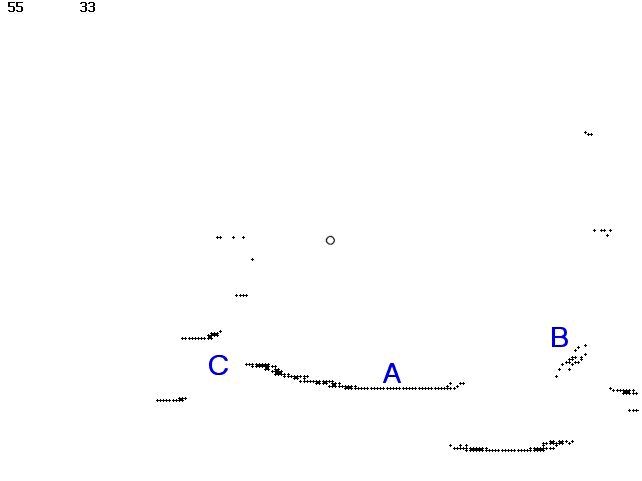
Figure 3. Sonar scan
The circle in the centre of the image represents the sensor. The other dots represent a solid surface. This image represents several scans of the same area combined to show that the readings are not always the same each time. This is usually caused by soft or irregular shaped objects. The Dots at point A represent a solid flat wall. The curvature is not due to the sensor but is because of inaccurate conversion to circular coordinates. Point B represents a person. Notice how the dots are more spread out. This is due to the persons clothes and they were probably moving slightly. At point C there is a clear space which represents an open door. Even a small part of the wall outside the room is detected.
The next task (Appendix D) was to get the computer to distinguish separate objects. This was done by placing ‘markers’ in the array whenever the measured range changed in comparison to the previous value by a minimum preset amount. This meant that the computer defined the start and end of an object if the current reading was reasonably different to the last. A screenshot from this program is shown in figure 4.
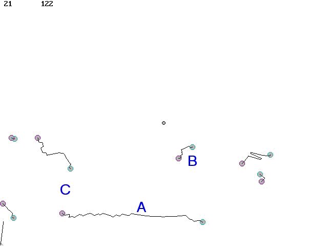
Figure 4. Sonar scan with objects defined.
Points A, B and C represent the same as before, but now it is clear that the computer has defined them as separate objects. This is not a fool proof method but it was found to work quite well. Combined with web cam data this could prove a very effective way for the computer to separate the world it sees into objects.
Several other test programs were also created. One program (Appendix E) was for controlling the MIRC remotely with a wireless keyboard. Another was for testing the shaft encoders (Appendix F). This program prompts the user for a number and then rotates until the shaft encoders count to the same value.
2.3.2 Multiplexing
To capture sensor data from the multiplexer a subroutine named ‘GetPlexer’ was created. This loop can read the value of the analogue input on the K8000, store it in an array and the switch the digital output to the multiplexer on and then off again. This process will loop until all 8 sensors have been read. Figure 5 shows the simple loop. See Appendix G for the full multiplexer test program
Next plex
| For plex = 1 to 8 | |
|
Calls subroutine to get value of AD channel |
|
Stores |
|
Tells |
|
Clears |
Figure 5. Multiplexer loop
2.3.3 Fuzzy Learning
In order for a robot to function effectively in the home, it must be able to adapt to circumstances that the programmer may not have considered. If the program was not able to learn and adapt, the user would soon find that the robots abilities were quite limited. No matter how many situations and tasks it was programmed to deal with, there would always be something it would fail to ‘understand’. This is why software developed for the MIRC uses fuzzy algorithms.
The current software does not involve fuzzy learning as this will take considerable time to develop, but example programs were created to demonstrate this. The first example does not involve learning but uses fuzzy logic to determine how the MIRC moves. This program (Appendix H) causes the MIRC to act like a finite state machine. [23] The program simply captures data from analogue range sensors on the front and sides of the MIRC. This data is then combined and converted to a value for the speed of each motor. If the MIRC approached an object that was on its left side, the right motor will slow down causing it to move away. The closer the MIRC is to the object the more the wheel will slow down, causing it to turn sharper. The outcome of this is that the MIRC behaves more like an animal than a machine. The QBASIC code for combining the sensor values and changing the motor speed is shown in figure 6 below.
|
Figure 6. Changing speed of the motor, relative to all sensor readings
This is one line of code. LTemp is eventually used as the speed value for the left motor. The other variables are the sensor values. This applied to both motors, causes the effect mentioned previously and also will cause the MIRC to slow down if passing through a small space.
Another example program created was a fuzzy line follower (Appendix I). This program uses similar algorithms to the object avoider program. Two photo reflective sensors are mounted on the front of the MIRC for detecting lines. Different types and colours of lines were tried and the relevant programs created for them, but it was found that slow polling of the sensors would only allow for gently bending lines to be followed. If a faster computer was available, sensor data could be captured faster and therefore sharper bends could be followed.
To demonstrate fuzzy learning, a program was created that simulated evolution. (Appendix J) The program creates a type of predator and prey environment where one species hunts another for food. The prey are just simple circles which move around randomly on the computer screen. Each one has its own set of parameters which define how fast it moves and how erratically it behaves. The predators are the evolving species which eat the prey, move around and breed. Each one has its own unique set of variables which governs behaviour. This is their simulated DNA. When the program starts several prey are generated and one just predator. The ‘DNA’ for this initial predator is randomly generated. It is attracted to the prey so it chases them until it is close enough to eat. Once the predator has eaten enough food it will make a copy of its self but with some slight mutations in its ‘DNA’. The mutations may have positive or negative effects, such as being able to survive longer without food, or becoming less agile. At first the majority of predators will group together, but by the time several generations have lived and died, distinct groups can be seen. Using this method, a robot could be the predator, and the prey could be its charging station or tasks it meant to perform.
2.4 Costs
The table in Appendix K shows a cost estimate for the hardware on the MIRC. Numbers shown in brackets are extra costs due to damaged components or extensive modification. The total cost does not include the various tools that were purchased in order to complete the project.
3. Conclusions
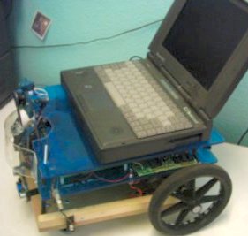
The resultant MIRC combined with a laptop appears in presentation as a robot. It has achieved its original objective of mobilisation of which can perform a range of simple tasks determined by the software used. Whilst the project has achieved its aims, there is limitless capacity to develop further to reach its full potential. With funding and further experimentation this humble foundation could prove a stepping stone to real functional usage of this type of technology. The production of an advanced MIRC is possible at a reasonable cost with mass production and as such could impact on everyday life.
Currently there is no main program or OS. Eventually it will be a mainly fuzzy controlled system. It appears rather pointless trying to create a precise, accurate system as it would cost large amounts of money and time to make it work. The intended outcome is to create a kind of fuzzy logic based cyber pet. This would mean that a MIRC based robot would act more like an animal than a sophisticated machine. Learning algorithms could enable you to teach it tricks just like you do with a dog, rewarding good behaviour and punishing it if it does something wrong.
Throughout this project a great deal of knowledge has been gained in various areas of cybernetics, and a significant project achievement has been reached. Images of the competed MIRC are available on the attached CD. The MIRC created for this project will continue to provide learning opportunities as it continues to develop and improve. A point to stress is how difficult turning theory into practice actually is. Testing very often showed unexpected results. A lot of time can be used getting things to work the way they were intended to, and very often a compromise is necessary.
4. Further Work
There is much more work that can be carried out on this project: – Once the oddometry is working effectively, a charging station for the robot could be built to locate when in need of recharging. Armed with a modern laptop, the next step will be to incorporate the webcam and wireless networking. With image processing a robot could recognise objects, rooms or even faces. Another thing to add is a robot arm. There are already robot arms available for purchase that can plug into a USB port, although a custom design may prove more effective. Eventually the entire MIRC will be connectable to a laptop by one single USB cable as this would make connection simple. Also a USB hub could be built in to the MIRC for simple addition of hardware such as robot arms or a barcode reader.
4.1 Networking
The ability of modern computers to connect to wireless networks is an important factor to the potential success of the MIRC.
4.1.1 Internet access
Being connected to the internet not only gives the MIRC access to large amounts of data. It also means that it could be connected to other networks such as mobile telephone networks. This opens the doors for a whole new interactive system. A person wishing to make a MIRC based security robot could monitor it from anywhere. Data and images could be sent to a multimedia telephone or instructions sent back to it. The most popular use of this is expected to be web conferencing. A person could use the MIRC like a remote avatar, allowing them to ‘step inside’ it and drive it around.
4.1.2 MIRC Networks
Laptop controlled MIRCs could be networked together, enabling them to work as a team to complete the same objective. This could even be done with the robots in different parts of the world. Groups of robots could be simultaneously controlled by a single user. Using the fuzzy style of programming described earlier, several robots could share all their sensor data and process it between them. This could act like a shared ‘conciseness’ making each individual robot more like a single part of one machine, rather than individual robots communicating and working as a team.
References
1. River Deep. http://www.riverdeep.net/current/2002/03/032502_robots.jhtml
2. Maplin Electronics. http://www.maplin.co.uk
3. Wikepedia. http://en.wikipedia.org/wiki/Moore’s_Law
4. Dylan Tweeny http://dylan.tweney.com/writing.php?display=331
5. Arrick Robotics http://www.robotics.com/
6. Kuka Robotics. http://www.kukarobotics.com/
7. Robot Engineering Task Force. http://www.robo-etf.org/
8. Open Automation Project. http://oap.sourceforge.net/
9. MSNBC. http://msnbc.msn.com/id/3078544/
10. Gordon McComb, Robot Builders Bonanza 2nd edition, McGraw-Hill, ISBN 0071362967
11. Forrest MIMS, The Forrest Mims Circuit Scrapbook, Volume 2, LLH Technology Publishing, ISBN 1878707493
12. Peter Bates, PC Interfacing Using USB, Babani Computer Books, ISBN 0859345351
13. Davis Chapman, Sams Teach Yourself Visual C++ 6 in 21 days, Sams Publishing, ISBN 0672312409
14. K8000 Yahoo group. http://groups.yahoo.com/group/k8000/
15. N.Kantaris, Programming In QuickBasic, Babani Computer Books, ISBN 0859342298
16. Velleman Components. http://www.velleman.be/
17. K8000 House alarm. http://perso.wanadoo.fr/2oo2/k8housealarm/index.html
18. I2C BUS. http://www.semiconductors.philips.com/buses/i2c/
19. Active Robots. http://www.active-robots.com/
20. FTDI. http://www.ftdichip.com/FTModule.htm
21. Milford Instruments. http://www.milinst.com/
22. Total Robots. http://www.totalrobots.com/
23. AI Depot. http://ai-depot.com/FiniteStateMachines/
4 Comments
Leave a Reply
You must be logged in to post a comment.
You could use the output from the 7414 to activate a small transistor. This could supply the 5V for the K8000.
A quadrature encoder wasn’t used but it would certainly give a better resolution.
By using a TTL 7414 i can obtain that digital signal! I tried this, but I don’t get the 5 volts that are necessary to activate the digital input. Have you considered using the quadrature ?
Thank you!
The encoder was made by placing equally spaced bits of white tape around the inner edge of the black drive wheels. A small photoreflective IR sensor was then added near to this to detect change from black to white. The output of this was put through a Schmitt triger to give a nice digital pulse output as the wheel turned. This was fed into a k8000 digital input.
The software simply counted these pulses. Each pulse represents a specific distance moved so calculation was simple.
The downside is, if your wheel slips, the software still counts it as if you have moved.
How did you connect an encoder to the k8000 interface and how did you programmed it ?