Electro Hydrodynamic Thrusters (aka Lifters)
Electro Hydrodynamic Thrusters (aka Lifters)
Courtesy of Blaze Labs Research
EHD stands for Electro Hydro Dynamics which is the study of the flow of a fluid under the effect of an electric field. The principle of ionic air propulsion with corona generated charged particles has been known as from the earliest days of the discovery of electricity. One of the first reference to sensing moving air near a charged tube appeared in year 1709 in a book titled ‘Physico-Mechanical Experiments on Various Subjects’ by F.Hauksbee. Many other pioneers of electricity, including Newton, Faraday, and Maxwell, studied this phenomenon. Unfortunately, EHD is not a common topic in most high school syllabus, which is the main reason why most of the general public get confused when seeing such devices in action.
An EHD thruster is an electro hydrodynamic device which ionises air and moves the charged ion cloud in a way and direction to transfer momentum to neutral air molecules. By Newton’s third law of motion, action is equal and opposite to reaction, and the EHD thruster will move in the opposite direction of the ion cloud. Ionocrafts was the name given to the first kind of vertical takeoff EHD thrusters designed during the early 60’s, and form part of the EHD thrusters family. Recently, this effect has gained popularity under the less appropriately titled ‘lifter’ which due to the lack of knowledge of EHD by most people, has been related to some sort of antigravity effect. It is a well known fact that these devices produce thrust along their own axis, and not against the force of gravity as would be expected from an antigravity device. An EHD thruster in its simplest form is made up of two electrodes, one with a sharp edge, the ioniser and one with a smooth edge, the collector, which when powered by a high dc voltage (a few kV ) produces thrust against the surrounding medium, normally air.
For construction details, see the DIY Devices section.
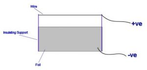
The diagram below shows a EHDT in its most basic form. It consists of a fine wire, suspended above a sheet of aluminium foil, by a lightweight insulating support such as balsa wood. If a high voltage DC source is connected as shown, a thrust will be produced, propelling the device in the direction of the positive wire. This thrust is due the motion of air, or any other dielectric (insulating) fluid around the device, as described below.
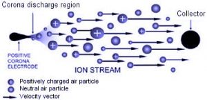
The top sharp electrode ionises the air. If the electrode is positive, free electrons in the vicinity will accelerate towards it, and strip off other electrons from the air molecules around the sharp wire.
A cloud of heavy positive charges is thus formed, and the avalanche of electrons approaching the sharp electrode account for the corona & ionisation current. In their mad rush from the ion emitter to the smooth negative electrode, the positive ions bump into neutral air molecules-air particles without electric charge. The force exerted on them by the electric field is offset by the force of friction caused by collisions of the ions with the neutral air molecules. As a result, ions drift through the air gap with an approximately constant velocity Vd, that is proportional to the electric field given by Vd=kE, where the proportionality constant K is called the ion mobility, the highest the value the more mobile (faster) and the less friction is offered.
The terrific wallop in these collisions hurls a mass of neutral air downward along with the ions. The distance in cm traveled by an ionised air molecule until it hits a neutral air molecule is given by the mean free path and is equal to 5 x 10⁻³/P, where P=760 Torr at sea level. The larger the air gap relative to the mean free path, which works out to be equal to 6.6 x 10⁻⁶cm, the more probability there is of an ion repeatedly hitting neutral molecules, and therefore the more impacts and thus effective thrust we get. During these collisions, the ion charge is not transferred to the neutrals. When they reach the lower smooth electrode, the ions, still being positive, hit it and neutralise themselves. But the grid has no attraction for the neutral air particles that got bumped along. So the air flows right along the sides of the lower electrode, making a downdraft of neutral air beneath the EHD device. The fact that most ions are neutralised at the collector explains why the reading we get from ion measuring meters setup below such devices does not account for the measured thrust. In fact for a good EHD thruster, such a reading should be close to zero. If however, one accurately measures the force exerted by the air exiting the collector side over a flat surface, it is found that this force is equal and opposite to the thrust of the device.
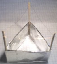
 An EHD thruster works without moving parts, flies silently, uses only electrical energy and when immersed in a fluid (air, oil, etc..) is able to lift its own weight together with additional payload. The basic design of the simple lifter has been fully described in the TT Brown US Patent N°2949550 filed in 1957 and titled “Elektrokinetic Apparatus”. Even though T.T.Brown was fully aware that the thrust from his devices was due to ion interactions, lack of EHD knowledge at that time, resulted in very low efficiency operation of these first EHD thrusters. Shown below is one of Brown & Bahnson’s designs described in US Patent #3,223,038, and an ultra simple EHDT made from aluminium foil, balsa wood and a fine copper wire.
While extensive research was performed in the 1950’s and 1960’s on the use of electric propulsion for interplanetary spaceflight, many promising concepts had to be abandoned due to the technological limitations of the power conditioning systems in use at the time. It is also understood that the research & development of ionic thrusters by NASA at those days was aimed mainly for interplanetary space flights, and the fact that ionocrafts need a fluid medium to work has led these fantastic devices to be largely abandoned by the scientific community since the late 1960’s.
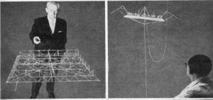
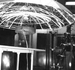
To date no consistent effort has been made to reevaluate these approaches in light of modern power processing technologies and develop flying machines to operate within the atmosphere. During the 1960’s a lot of work on EHD technology had been accomplished by Major De Seversky (pictured below). De Seversky noticed an air flow developing between the two electrodes of an air ioniser commonly used to clean air. “To an old flyer like me,” said the major, “anything that stirs up a wind is a flying machine. So I began to develop the idea.” In fact a few years later, he patented The Ionocraft patent no:US3130945 in April 28, 1964. The major seemed concerned that the Ionocraft might be mistaken for a kind of space vehicle. “This is not a spacecraft,” he explained emphatically to forestall any possible misunderstanding. “It’s an airplane, designed to operate within the atmosphere. But it will be able to do things that no present type of aircraft can accomplish.” Indeed, this misunderstanding still prevails in the present days, but Blaze Labs research clearly shows that EHD thrusters and lifters do not work in vacuum.
End of Blaze Labs Article
Note that the Bifield Brown Effect is an effect apparently produced by capacitors or electrodes that are asymmetrical (of different sizes). This is what causes the majority of confusion around the “Lifter” devices. You can see from the images that one electrode is significantly larger then the other. Most Lifters or EHD thrusters are powered with voltages below 30kV. It is said that the Bifield Brown effect would become more apparent at more extreme voltages such as above the 50kV mark. The vacuum tests performed by Blaze Labs were performed with a Lifter powered at 30kV. NASA have also performed vacuum tests on a rotational lifter setup powered at 50kV. These tests are not 100% conclusive but it seems unlikely that a device based on the design of a Lifter will have any significant implications for propulsion technology.
For construction details, see the DIY Devices section.
54 Comments
Comments are closed.
But will a Van De Graff generator have enough current to power it?
Also why does it have to be very tiny? is it because of the high voltage generated? If I use a larger Van De Graff can I build a heavier lifter? Thanks
Maybe a very very tiny one.
Could I use only a Van De Graff generator to power a lifter?
This reduces the electric field gradient and therefore will not improve it.
What happens when the positive electrode wire is run back and forth many times or perhaps coiled? Would this not generate much more ionized air, and as a result increase thrust?
See this post.
Hi Guys.
Interesting reading through the information provided. Can anyone tell me what is the maximum payload in kg’s that one of these can lift ? Also, does the use of a fluid medium increase effiency (such as oil?)
Mike, I think you’ve read one too many conspiracy books. But I wouldn’t mind finding one of those “warm holes.”
The information provided on this site is for educational purposes and therefore is based on easily verifiable evidence rather than speculation.
I have read one of the books you mentioned to me. I think it is interesting that the authors of such books are happy to explain how this amazing technology works yet I have not seen any evidence of it. Not even a simple benchtop demonstration (Except the hutchinson effect(s) which is very interesting but has not yet been replicated publicly to my knowledge).
It is most likely that there are experimental aircraft being flown in our skies and the use of UFO/Alien stories makes a great cover for them. These things are secret for a reason. You should not be trying to publicly expose whatever research is going on.
As for the wormholes and visiting anywhere in the universe… come one now, that is just speculative fantasy.
Since this is an “educational service” I wanted to correct or update your information listed on this site. Nikola Tesla was the original inventor of the electro-magnetic propulsion aircraft now known as UFOs or flying saucers, way back in the late 1800s and early 1900s. Anyone in the know…knows that they are not manned by “aliens” like they would like to have us believe. The technology is simple really using very high voltage generators or Tesla coils. Also, for your information this technology was by no means abandoned but since the U.S. chose to ridicule Nikola Tesla when he introduced his incredible electro-magnetic propulsion aircraft and wireless transmission of energy to them, the Germans (Nazis) took him very seriously indeed. So as history would have it and as unfortunate as it may be Nazi Germany and not the U.S. was the first to fully develope this technology as was quite evident by the Foo Fighters and later the full blown mother ships which were originally made from submarine hulls to act as airborne aircraft carriers for the smaller saucer type aircraft. Imagine how embarrassing it was for the U.S. to have had Tesla as one the greatest inventors and geniuses of all time right here in America under their own noses and to have to later play catch-up to the Germans who saw the incredible potential of these aircraft and electro-magnetic technology. This catch-up game began at the end of World War II when the allies (mainly the U.S. and Russia) acquired this technology from secret underground Nazi bases and recruited/imported the men/scientists from Nazi Germany. Since the late 1930s the aircraft designs have varied from saucer/lenticular cigar/sphere shaped until recently where we now have massive triangular shaped aircraft as seen by thousands over Phoenix (the Phoenix lights) and other parts of the world. You can be sure that with the advent of computers and super computers which now employ artificial intelligence technology these aircraft have become quite advanced and complex able to travel anywhere in the universe if they wish to using naturally occurring and man made vortexes and warm holes. These are found throughout our planet at key electromagnetic hot spots such as Sedona, Arizona, Stonehenge, the Bermuda Triangle and many others known to previous cultures such as the Egyptians, Mayans etc. Tesla himself pictured (and had created) the wireless transmission of energy to power these aircraft anywhere in the world using the earth’s molten core as a medium by means of his tower/s such as the one built in Colorado Springs. Although to most these aircraft/spacecraft would seem of “extraterrestrial” or “alien” origin they are very much man-made. Tesla of course has been pretty much erased from history since this technology is considered by our government and those of most nations beyond top secret!!! As to how to build one of the simple versions of these aircraft or find out the big “why” the massive efforts to keep us believing these are “alien” aircraft (Answer: Free energy…lots of it!) just obtain a copy of Pentagon Aliens and Occult Ether Physics by William Lyne.
“The truth is out there” but it’s not like the X files version. Stay informed folks!
I think you’ll find that is “freaks”. Haha!
You People are Weird Science freks!!!!!!!!!
I’m guessing you mean a size to carry a person.Most lifters can only just lift themselves. I don’t know of any that has even been able to carry its own PSU.
How much power would a fully functional size flying vehicle need
See the big diagram with wires marked +ve (positive) and -ve (negative or ground)
after it is built wher do i conect power suppy i need help in that part of the proses so i dont burn down the house ha ha plese i want to make this work.
18g lifter consumes about 0.125 watz.
Ozone conversion energy included in that.
Suladead,
It forms ozone but I couldn’t comment on the effect on fuel efficiency.
The circuit to do as you require is just a common bridge rectifier. This can be made from four high voltage diodes. I suspect placing it a tube would increase drag but if the thruster its self was designed in such a way this could help with efficiency.
Kevin Sullivan,
The video clip on the DIY EHDT page shows a tiny lifter of just a few cm. Even tinier ones should work well too but at some point there will be a limit of size vs having sufficient electrode spacing for the high voltage needed for ionization.
I am wondering if this would work on a smaller scale. Small palm sized models or smaller to the micro.
Or is the lift effect due more to displacement? The bigger the better?
This is a field with fascinating possibilities.
Would it be possible to set up a circuit that could take an ac current and everytime the voltage flips it changes which wires it energizes, so you have to sets of corona wires one positive and one negative at the same time? how would this effect efficiency? Also, how much of an impact does putting the whole assembly in a lightweight tube cause? Would the focusing of the air around it cause an increase or decrease in efficiency?
I was wondering, I know that if the corona emitter is positive it forms nitrogen ions and if it’s negative it forms ozone. Could this be used as an ozone generator on the front of a liquid fuel engine to increase burn rate of the fuel inside the engine?
No DIY project as it is technically difficult/expensive and dangerous. This site shows how it works.
To say your website is excellent is an understatement. So far I am very impressed. Question: you mentioned mircowave propulsion. Do you have a DYI link you can post for this topic?
New means of propulsion/repulsion/travel or what-not will boil down to ingenious uses of materials and electronics. One reason why I don’t participate in SETI@Home is because we stand little chance of intercepting alien radio communications; advanced civ’s will be communicating in the quantum realm, sub-space – call it what you will where time is removed from the equation so that communications are instantaineous. The same goes for interstellar travel. If we could devise a way of doing away with time then space and thus distance become meaningless. This will only be accomplished when we figure out how to do things in the quantum realm. Since we only have a certain number of elements I propose that any new “engine” we may use to go FTL will be made of materials or combinations of materials and electronics. We’re on the doorstep to quantum computing with one Canadian firm already producing a quantum chip, we use [quantum] tunnelling diodes. My gut feeling is that when we can figure out how to make special combinations of materials resonate we may be on the way to the stars.
Yes an ion is deflected when it travels at a right angle to a magnetic field. This would cause it to circle or spiral. The direction of them depends on the polarity of the magnetic field relative to the polarity of the ion. This effect is used in devices known as cloud chambers for identifying partices by yhe way they move in the presence of a known field.
Magnetic fields are often used to confine plasmas in various systems. A penning trap forms a pair of ‘magnetic mirors’ to trap a non-neutral plasma. A tokamak is a toroidal system used ofr containing plasma for nuclear fusion research.
You could make some sort of air cusion i gues sin theory, but it would require huge amounts of power to maintain any lift like you describe, thus making it impractical.
Thanks for the excellent website.
If an ion encounters a magnetic field, will it move in a circular path? Will positive ions circle in on direction, and negative ions in the opposite direction?
Is it possible to contain a cushion of ionized air with a magnetic field?
Could this be used for a new kind of hovercraft which uses a ‘magnetic skirt’ to trap ionized air?
I have a feeling that the ions might spiral away from the magnetic field and the hovercraft would not work.
Would a toroidal coil be effective at containing ionized air?
A charged particle is not repelled by a magnetic field. A moving charged particle will be deflected from its path of travel. This means if an ion (charged particle) moving from one electrode to another passes through a magnetic field which acts at 90 degrees to the direction of travel, the ion will deflect towards one of the magnetic poles.
If the magnetic field is in the same direction as the direction of travel of the ion, no deflection (or acceleration) will occur.
I recommend you read out introduction to electromagnetism to get a better understanding of some of the underlying principles.
Apparently they will work with either polarity although I think it is better if the wire is +ve.
Thanks, but.. well.. you think it would be possible to deflect them away from the pointy electrode? Like having a magnetic field around it, so that when the particles become charged they instantly get repelled by the magnetic field? Can you actually repel a positively charged particle with a magnet? If yes, then which pole repels it? Could be some of those dumb questions again.. but i just can’t wrap my head around this particular problem.
Oh and one more! Does the device preform the same way no matter the polarity, or does it have to have + in the “front”?
A steady magnetic field will deflect a moving charged particle but not increase its speed. You would need a precisly generated alternating field. Some particle accelerators use a beam of microwaves in a wave guide.
Thanks a bunch for clarifying how that do-hickey works! When i get home after 9 months i think i’ll try to build myself one…
just one stupid question; can i accelerate the positive particles further with a magnetic field instead of an electric one? I’m so lost with this stuff 🙂
have been working on the field or force that is created between charged poles dif frq at .7 12mev produces diferent reaction you need electron brakdown reactor like nukler brakdown will contact later this works in a vacume
Here is a link to the “b-IONIC Airfish” by Festo. It is a blimp that moves (slowly) using the principals discussed here. On page 2, they have a very slick video showing the blimp in action. To the right of the video is a link to a PDF with a lot of detailed info.
http://www.festo.com/INetDomino/coorp_sites/en/df10fdeeb58db201c12571b9002ba9c4.htm
From what you have described, to gain more thrust, I would need a higher voltage, would a voltage of 100KV be a sencible figure, or should it be more practical to use a lower voltage that just causes the air to ionise and step up the current?
Im just going on the fact that at higher voltages the particles are accelerated to a much higher velocity.
u should see what happens when you put 4 ignition coils in series and also use high power caps with your ign. driver ic… it makes a interesting noise and rush of air before burning smoking the wire…
Where might I find a diagram of the second (acceleration) stage structure? It’s a wonder that these aren’t often seen on EHD thrusters – considering the extreme increase in efficiency provided by a well engineered two-stage system.
Has anybody heard of the Searl effect?
Long story short, for some time now I have been trying to find out if there are any studie’s that have been done on the resistance through an arc.. not across the electrode to electrode but throught the arc itself if any one could point me in the right direction it would be of much asistance
I don’t know of a store selling an ion craft, but you can find the HV power units in our shop. We will also have something simmilar available in about a month. If you want to be informed when we rlease new producs or info, sign up to our newsletter.
Just connecting a car battery will not move a lifter unfortunatley. You are correct in thinking that 600A would be good. The thrust of a lifter is proportional to the current, but they need at least 1kV (1000V) to work. This is because the high voltage causes the air to become ionized and mobile. Without enough voltage to ionize the air, nothing much will happen.
I need to know how I can hook one of these ionocraft up to a high voltage generator.
I also would like to know what store/place sells them.
I’ve finally built the bloody thing and just need the generator. I am still going to try the car battery idea, tonight hopefully. Would a car battery with 600 amps power the ionocraft up?
This has been used to cool a PC before. The author suggests the power consuption is about the same. See this Ion Cooled PC.
Hi guys im currently in the last quarter of a Higher National Diploma in Mechanical engineering and for my project i have been exploring ways of cooling computers and have a great interest in this technology. do you think that an EHD thruster design could be integrated into a computer to create the airflow over the heat syncs? i know you mentioned a fan is more efficient at moving air but i was wondering that if the assembly was multistaged or optimised with tubes that it could offer a compact (and lower power?) alternative to noisy fans?
It looks like microamps on the meter too, but I still think it sounds small. He doesn’t mention the voltage but if it were 33kV, the power would be about 1 watt. Maybe the lifter he made is very light, but the mention of “no crona” probably isn’t accurate. Maybe he is just refering to visible corona.
Sorry.
The guy Tim Venturas says the lifter’s “consuming” 30 uA. I apologize for the mix-up.
It looks like any other lifter. 30 uA, I beleive, can’t be enough for this thing. Well, here’s the address to it. Make sure you turn on the volume.
http://www.americanantigravity.com/video/Lifter4-D1a.MPG
Personally, I think he mispronounced the word. If that lifter can hover at 30 uA, then a car battery should send it through the roof.
I will see to this and make sure if it is possible. I’m testing what this guy said!
30uA sounds pretty small for a standard lifter, but maybe this is somehow a different arrangement. If you have a link to the video please post it here.
I found a video of a rather large ionocraft hovering around 2 feet powered by just under 30 microamps. I know you need high voltage for lifters, but is it possible to get one to fly with 30 or so microamps?
I really couldn’t say if an EHD system could improve its range or not. I’ve only had brief practical experience with small foil types.
Haplo (above) mentions that the power-thrust efficiency is about 1%, so you may only get 660W worth of thrust.
I’m not sure if anyone has tested an EHD in an exhaust jet, but I expect it would work quite differently. You can see in these pictures of plasma that a hot jet has a noticable effect on a HV discharge.
Maybe using the EHD on the wings (if it has any) or chassis to reduce drag or control airflow around the craft would be a more efficient way.

So if I ran say, the full amount of electrical power generated by the turbine, say 220 Volts/300 Amps?
I am not worried about lift as much as I am thrust. I am trying to find a way to make a light experimental aircraft have a longer range.
Probably not much, if any at all. You may be able to add some extra thrust, but it would need a lot of electrical power.
If I wanted to vent a turbine’s blast through an EHD, how much of an increase in efficiency could I conceivably get from the thrust?
It’s not as efficient as a fan for moving a lot of air.
How do these compare in efficiency to an electric fan for the simple task of moving air?
For a single stage thruster (ie an ionocraft, most all of the EHD devices you see fall into this category), the power-thrust efficiency is about 1%, actually about 0.95% based on experiments. This comes out to 0.0098 newtons per watt. Note that this figure only applies to ionocrafts, where the acceleration of the ions is done by the electrodes that create and attract them. Because of this, the % ionization of the air and the speed of the ions is linked, so you can’t really adjust it to maximize the force, speed, or density of the ions to maximize the force they deliver to the air. More advanced EHD designs (which, from what I’ve gathered, really aren’t ever built nor get much serious attention, which is a shame) put a second stage between the ion source electrodes which is basically a particle accelerator. Most simply, it’s a series of parallel capacitors which operate under a specific AC frequency (which can be variable to match ion drift velocity) so that a plate will reverse its charges and either attract or repel ions around it. If you have, say, a single capacitor of two plates and a positive ion moving normally between them (toward the destination electrode), first the capacitors would be +-, pushing the positive ion away from the positive plate and towards the negative one, then (based on drift speed), the current alternates and they become -+, so that the ion is pushed further down by the trailing electrode. Basically, you’d design such a thruster like you would any aircraft engine, only specifically as one lacking moving parts (like a ramjet, or better yet a scramjet, which offers low drag). Also, like an aircraft engine, EHD thrusters benefit from compression of the air (compressed air has higher density, and is forced into more collisions with ions, which accordingly increases efficiency) and are hurt by drag. EHD thrusters have a lot of advantages over conventional air breathing engines though. Namely, no moving parts whatsoever are required, 100% energy efficiency (for a well designed thruster), EHD thrusters aren’t affected much by airspeed (ie there’s no flame to go out or fuel to incompletely combust), the engines can be very precisely controlled without moving parts (you can vary the thrust by modifying the wattage and frequency of the acceleration stage), EHD thrusters produce no heat, noise, or notable exhausts (they can produce ozone and NOx, but you can design specifically to reduce this to neglegable levels) , and the operational parts don’t impose much constraint upon shape, so an EHD thruster could have entirely smooth internal surfaces, offering less than minimal drag compared to any given conventional engine. Furthermore, the acceleration stage can also be used as a regenerative air brake. Ions being pushed along by the air are a moving charge, and thus present a voltage. By collecting that voltage, you slow down the ions, which collide with air and slow it down as it moves through the engines, slowing the craft and producing electricity from the lost velocity.
The main disadvantages of EHD thrusters aren’t really part of the thruster design, but simply the fact that currently chemical fuels have a higher energy density than any electrical power storage devices. Such a craft would require either batteries or a generator. The former would have to be quite massive (compare to an electric car) and the latter would nullify any advantages of the engine design (ie portable generators are inefficient and require their own fuel source).
The efficiency of an ElectroHydroDynamic Thruster is highly dependent upon its design and operational voltage. A typical value could be a thrust of 1g per Watt.
The minimum voltage needed to produce thrust is dependent upon the distance between the two electrodes. The voltage commonly used in DIY lifter experiments is usually between 10kV and 30kV at around 1mA
What’s the theoretical efficiency of a EHDT?
What’s the minimum DC voltage & current required to operate it?