Voltage Multipliers
Voltage Multipliers
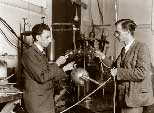 One of the cheapest and popular ways of generating high voltages at relatively low currents are the classic multistage diode/capacitor voltage multipliers, known as Cockcroft Walton multiplier, named after the two men who used this circuit design to be the first to succeed in performing the first nuclear disintegration in 1932. James Douglas Cockcroft and Ernest Thomas Sinton Walton, in fact have used this voltage multiplier cascade for the research which later made them winners of the 1951 Nobel Prize in physics for “Transmutation of atomic nuclei by artificially accelerated atomic particles”. Less known is the fact that the circuit was first discovered much earlier, in 1919, by Heinrich Greinacher, a Swiss physicist. For this reason, this doubler cascade is sometimes also referred to as the Greinacher multiplier.
Unlike transformers this method eliminates the requirement for the heavy core and the bulk of insulation/potting required. By using only capacitors and diodes, these voltage multipliers can step up relatively low voltages to extremely high values, while at the same time being far lighter and cheaper than transformers. The biggest advantage of such circuit is that the voltage across each stage of this cascade, is only equal to twice the peak input voltage, so it has the advantage of requiring relatively low cost components and being easy to insulate. One can also tap the output from any stage, like a multitapped transformer. They have various practical applications and find their way in laser systems, CRT tubes, hv power supplies, LCD backlighting, power supplies, x-ray systems, traveling wave tubes, ion pumps, electrostatic systems, air ionisers, particle accelerators, copy machines, scientific instrumentation, oscilloscopes, and many other applications that utilize high voltage DC.
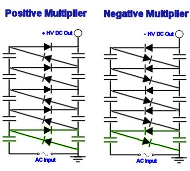
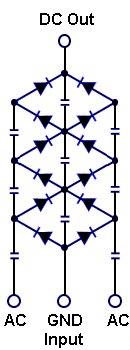
 The polarity of the high voltage output is simply determined by the configuration of the diodes, as shown in the diagrams above.
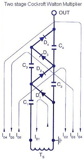
2 stage multiplierThe Cockcroft Walton or Greinacher design is based on the Half-Wave Series Multiplier, or voltage doubler. In fact, all multiplier circuits can be derived from its operating principles.
It mainly consists of a high voltage transformer Ts, a column of smoothing capacitors (C2,C4), a column of coupling capacitors (C1,C3), and a series connection of rectifiers(D1,D2,D3,D4).
The following description for the 2 stage CW multiplier, assumes no losses and represents sequential reversals of polarity of the source transformer Ts in the figure shown below.
The number of stages is equal to the number of smoothing capacitors between ground and OUT, which in this case are capacitors C2 and C4.
- Ts=Negative Peak:C1 charges through D1 to Epk at current ID1
- Ts=Positive Peak:Epk of Ts adds arithmetically to existing potential C1, thus C2 charges to 2Epk through D2 at current ID2
- Ts=Negative Peak:C3 is charged to Epk through D3 at current ID3
- Ts=Positive Peak:C4 is charged to 2Epk through D4 at current ID4. Output is then 2n*Epk where N = number of stages.
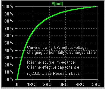
Several cycles are required to reach full voltage. The output voltage closely follows the curve of an RC network as shown above. R is the output impedance of the ac source, whilst C is the effective dynamic capacitance of the CW multiplier. This charging occurs only upon switching on the CW multiplier from a discharged state, and does not repeat itself unless the output is short circuited. Most common input AC waveforms are sine waves and square waves.
 Three stage CW multipliers, commonly known as tripler, were used in most of the early B&W and colour TV’s. The voltage drops rapidly as a function of the output current. In some applications, this is an advantage. The output V/I characteristic is roughly hyperbolic, so it serves well for charging capacitor banks to high voltages at roughly constant charging power. Furthermore, the ripple on the output, particularly at high loads, is quite high.
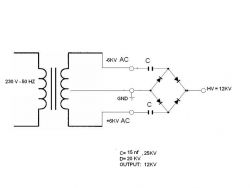
Increasing the frequency can dramatically reduce the ripple, and the voltage drop under load, which accounts for the popularity of driving a multiplier stack with a switching power supply. A clever way to reduce ripple is to implement a full wave voltage doubler as shown below. This effectively doubles the number of charging cycles per second, and thus cuts down the voltage drop and ripple factor. The input is usually fed from a centre tapped ac transformer or MOSFET H-bridge circuits.
A DIY Voltage Multiplier
 A voltage multiplier is a great way to create a high voltage DC power supply. It is very easy to generate high voltages from easily available components. The next section contains information on where to buy the components and how to connect them. It also gives details of sources of high voltage power supplys which will run from batteries. Check out our DIY articles for more details
This information is for educational purposes. Replicating this project is done so entirely at your own risk
More DIY Voltage Multiplier/science/diy-devices/diy-voltage-multiplier
153 Comments
Leave a Reply
You must be logged in to post a comment.
Hi, I wondering if is possible use the voltage multiplier directly from line voltage (220VAC /50 hz in my country), because I’ve been seening a lot of design that start with low voltage o from DC. I would like to step up from 220 VAC to 10-15 kVdc in order to use it in an electrostatic precipitator. Which capacitor would be suitable to do this?
Hope you can give me some guidance.
Regards.
Yes you can do from line voltage directly. I can’t advise any component values for you, but it generally depends on the load current and acceptable ripple in the output.
You need to use some TVS, MOV, or safey spark gaps between the transformer terminals to prevent over voltage spikes from destroying it.
Dear Sir,
I have made a voltage doubler by using a 12KV mid-point grounded neon transformer. The problem is transformer damage just few seconds after arcing between output(12KV) and ground point.
How I can protect neon transformer when I want to produce a continuous arc in output of voltage doubler?
Now I have a damaged neon transformer with a high no-load current but doubler circuit elements are completely OK. (diagram is as attached)
Could you please tell me how I can modify my circuit in order to use it for producing a continuous arc for a few minutes without neon transformer failure?
Godwin, This is a DIY project, we can not do it for you.
Manolo, Yes.
Zeeshan, I would think the two in series are to give a total voltage tolerence or simply spacing, that is double that of a single one. Using just a single one risks blowing the diode.
I have obtained reference from web search and really grate information i have found.
I am working with some Baggage Xray Machines / Generators so they have Voltage Multiplier Circuit in the Xray Generator generating 150KVA.
I need your assistance when generator energized then sometime it stop working and i have found that last stage of the multiplier there are 2 diodes in series and one these DIODE maybe has some leakage.
Would you please kindly suggest me, what if i remove one diode??
Best regards
Shan
Hi, can I use this to convert 200VAC IN to 400VDC OUT?
Hi, I want to build a variable voltage multiplier from between 1kv to 30kv and i want it to be powered from mains.im not very good with electronics so the easiest circuit will be appreciated. I also do not want a transformer in the circuit. thanks
Is that a string of resistors from output to GND? What value are they? I would suggest first trying with just 1 or two stages to make sure that your components are not faulty. Placing diodes in series like this is not very reliable.
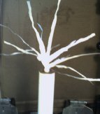
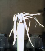
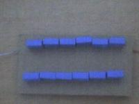
Sorry, the previous photo shows the output end of the multiplier.
Here is another photo. In this photo the left side is the input side of the multiplier.
I can’t see were you are connecting your transformer or where your output terminal is.
Hello, I have constructed a voltage multiplier that does not work. I am using a microwave oven transformer to power the multiplier, and I have used 1N4007 diodes, 3 of them connected in series for a 3000v rating, and 3kv ceramic disc capacitors. I constructed 120 stages, but I have also tried just connecting 30 stages and still have not got anything to work.
Here is a picture of my multiplier. What am I doing wrong?
Thanks in advance.
Sir,
please link me to any person who will help me design voltage multiplier, using 360v/200uf and 6amps/600v diode.
This should produce 1,200volts of dc when 120vac is being put.
Thanks and God bless you.
Ben, Kenji,
I think there is enough information between this page and the DIY Multiplier page for you to work out what is needed.
It is important for you to understand what you are doing so that you can be fully aware of the dangers.
Hi,
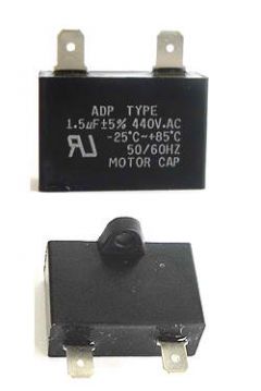
Can I use the capacitor from an old Electric Fan that have a voltage rating of 400v and have a capacitance is 1.5uF to make this voltage multiplier?
hello! I am building a coil gun i have all the pieces so here is the layout 11.1v 3000mah 20c lipo battery -> dc to ac converter (car to home outlet converter 100 watt) -> To a 5 times voltage amp. -> 100ohm @ 50wat resistor (neg terminal)-> 5 470pf 200v capacitors lined in series.
questions are:
1: if i build this style of volt amp what kind of and how many capacitors/diodes should i use that can take the power?
2:are there any problems with the components relative to the power?
3: any suggestions or advice?
Sorry, I think that is beyond the scope of this page.
hi
for testing inverters i need a variable DC voltage from 100V up to 1000V, i will use a combined design which consists of first a up transformation followed by a CW multiplier, i was thinking about using the rectified 100 Hz ripple or producing PWM pulses, what are the (dis)advantages of both? thx
For a bipolar output, you simply make two multipliers and power them from the same supply. The orientation of the diodes will determine the output polarity.
Thanks for the fast reply!
My input will be the 230VAC 50Hz, from the mains.One phase.
Do you think a pulsed power supply will do better?
Also any idea on how I can have floating voltage with a multiplier(like +20 and -20, and not 40 to ground)?
It depends on your starting voltage. 40kV @ 40mA is 1.6kW so you will need something pretty powerful.
Hi, congrats about your site!
Well, I want to make a high voltage supply to charge h/v capsacitors.I need to generate 40kV, at around 40mA. Is the Voltage multiplier good enough or capable for such an application?
What about pulsed power supplies?
Using a higher input voltage may cause it to overheat of for the insulation to break down.
10kV cap will work with an 8.5kV input. Generally though it would be advisable to use components rated for twice the supply voltage.
I Have an 8.5 kv DC 1.6ma tranformer. the input voltage is stated as 100v AC @50 to 60 Hz 50ma.
I run this from a 240 to 110v Ac 50ma converter. I intend to make a voltage multiplier using this as a power source purely for the hell of it. My question; will 10kv capacitors work with an 8.5kv input and if so which diodes should be used?
Could running the transformer at UK mains voltage damage it or other componebts that may be inside, the whole transformer is ecapsulated in a pitch like substance in a steel case so I cannot see any other components that may be hidden in there.
There’s not a lot you can do except for filling the space with a dielectric material while leaving a path for the electrons.
Any gas in the tube will seriously impede the electron flow and will cause deflections that may cause them to miss the hole.
I would like to accelerate electrons inside a cold cathode vacuum tube with the output of a positive voltage multiplier. So the electrons would be attracted to the positively charged plate. There is a hole in the plate through which they will pass, so the electrons do not hit the plate. But since there is a bit of gas in the vacuum tube to facilitate the electron flow from the cold cathode electron gun the voltage multiplier would likely ionize the surrounding gas and so the gas would start to conduct electricity. The voltage on the multiplier would drop significantly if that happened.
Do you have any ideas how to insulate the plate connected to the voltage multiplier to stop the electron discharge but still keep the electric field intact and so usefull to accelerate electrons.
Thanks for any comments
Whatever you use will most likely be non-polarized material. The polarization in some capacitors occurs because they have a special configuration such as the liquid electrolyte in electrolytic capacitors.
Hi, in refernence to my capacitor question above, the capacitors in a voltage multiplier have to be non polarized, correct? So I would have to choose a dielectric that is has non polarization properties right? If so where can I find a chart or something of different dielectric materials with information about dielectric material polarization properties?
Thanks again for your help and
Happy New Year!
It might be tricky to make work in practice. All the washers and connections sounds difficult. If you can master that part, then I don’t see why it wouldn’t work though!
I would recommend making and testing just one capacitor first so you can be sure it can tolerate the voltage you will apply to it.
I am thinking about building my own high voltage capacitors to use in a voltage multiplier circuit. I am thinking about using a polyethylene dielectric body and washers for the plates, the plates will be covered with a small bolt protruding for the terminals. I was also thinking about a tube type with mineral oil as the dielectric. Is this feasable or is it more complex than I think? And what do you think about the materials I suggested? I love your sight and thanks for your help.
Twice the input voltage or more.
How do you determine what voltage value needed for the capacitors and diodes? Thanks
It will be causing a voltage spike on the ground of your supply. It cuts out for protection because it sees that as a fault. An ATX supply is designed for stable operation in a PC so it will not like to work under such conditions.
I am currently building a high voltage circuit for experimentation purposes and am running a CC Inverter off of a modified 250w ATX PSU.
I can get small arcs (3mm – 4mm) when connecting the two AC connections of the Inverter but when i connect one of them to a ground connection the PSU cuts out.
Could this be the overload protection on the PSU or another issue?. The Inverter only puts out around 30ma so I am assuming that it should not be drawing too much current form the PSU.
You can’t use 470uF capacitors. At 50Hz they have an impedance of under 7 ohms. This would mean 35A of current. The 1n4007 is only suitable to 1A. Standard mains sockets are only rated for 13A too.
If you are using a variac, there’s no need to try to switch different voltages.
I’m planning on building a 10-stage, full wave multiplier using the input from a 1.5A 0-240V Variac, to get up to about 5kV. I’ll be using IN4007 diodes and 330V 470uF capacitors, which should be fine given that they’re only exposed to peak input voltage.
I want to be able to tap from the multiplier at different stages though, using switches. For example, tapping out at stage 6 would isolate stages 7-10 and redirect the current to the output terminals, and I don’t know quite what kind of (affordable) switches to use. If the switch is “inactive” (for example, simply connecting stage 6 to stage 7 and beyond), it’s only exposed to the initial voltage/current, but if it’s “active” (from stage 6 to output terminal), it has to be able to withstand the entire voltage produced by however many stages are being used. Any ideas?
Yes, The SG-LCR2M is not really suitable for driving high voltage multipliers.
I would like to drive an external coil with a square wave signal at 800V, 100 mA at about 100 kHz in a ringing LC circuit.
I have the SG-LCR2M resonate signal generator. Using the Blaze Resonate Multiplier calculator I find that 4.7 micro farad capacitors in 24 stages can accomplish this.
Question: Can I use a florescent Light balast with 120V input and 277V output as a power source to replace the SG-LRC2M and also reduce the number of stages of the multiplier.
thank you in advance.
You can work it out using ohms law. Decide what current you want to limit to (you can google around for what might be considered as safe), and then use the formula R = V / I
Where R is the resistor value needed, V is your calculated peak output voltage, and I is the current you want to limit to.
When you use high ohm resistors in a hv circuit, you need to make sure that there is no possility of sparks just jumping over the surface of the resistors and thus bypassing any saftey precautions.
Can you please assist me in the sizing of output limiting resistors. With reference to a 240Vac Supplied 30 stage half wave multiplier using .22uF Caps and 1A In4007 Diodes would two 3.5kV 10Mohm Resitors in series before the output be sufficient limiting the touch potenial if someone was to touch the output pins
Yes, your output would be at its max for more time if there is less ripple.
Hi RCB
I plan to build a 240VAC mains voltage supplied negative ion generator (To use for Oduor reduction). The circuit is as per your negative voltage multiplier with 30 stages(Output 14kV?) but with a couple of 10Mohm resitors to limit the touch potentail in line just before the DC outut pins. Could you possibly offer any advise on selecting the capacitor uF (I have seen circuits using .01uF and also circuits using .22uF Caps) (My understanding is that the higher value cap will allow higher current draw and offer more ripple smoothing but my question is will more this smoothing aid the Air Ionisers perormance?
Geoff,
This will not work. The multiplier is charging capacitors and will smooth out your modulation signal significantly.
The CCF circuit either can’t tollerate the voltage spke created when you make a spark or it can’t tollerate the surge current when it tries to recharge the empty capacitors. Try using smaller capacitors and/or put a resistor between the CCF and the multiplier input.
Thanks for all your comments,
I have build a ionizer from a ccf lamp and 4 stages of diodes and caps. As I didn´t have hv diodes I used 2 4007 in series on each stage. It seems ok, I can feel the ion wind at the end. Do you think that could be ok in the long term?
But, if I try to make a spark the ccf blows after some seconds. Could that problem be solved with a high resistor? what do you mean when you say that the resistor has to be in the input? is it before the ccf or is it between the ccf and the multiplier? should I use also the fuse? if the ccf lamp was 15w, will a .5 A fuse works, or I should use a minor one?
Yours is the only site I have found excelent answers. Thanks!
Hi there! I am trying to find a way of driving a 12″ plasma globe using common components and without having to use a flyback txr. If I was to drive a full wave multiplier from a 100V audio txr at say 100KHz, would it be feasible for me to pulse that input signal at say 10Khz to obtain the required pulsed DC output? ie. pulse the higher frequency driving signal at my desired pulsed DC frequency. ANY ideas, comments, or suggestions would be extremely welcome!
The voltage accross each diode will get less as you go higher up. Each diode drops some voltage. Measure the voltage between ground and points on the circuit.
hi,
i’m making a negative ionizer with 30 .01uF 1Kv caps and 30 1N4007 diodes, with input of 220VAC. I’m having an issue with low output. I have yet to measure the output directly, but I have measured the voltage over each diode. The first diode reads out as 220V but decreases after that, and the final diode reads out as 50V. I’ve rebuilt the circuit several times being extra careful with ensuring the connections are correct, but I still get the same results. There seems to be an output, but I feel that with 30 caps/diodes the output should be higher. Any ideas of whats going on and how I can fix this?
Thanks
I need to build bug Zapper.. I want it at least the commercial zapper (5600v 9mA) if more current i guessed its better… does anyone can help me with how many multipliers n the capacitor…
does the Dioda N4007 can be used?
Okunz,
You will have to do the calculations yourself for how much current it will draw. I just don’t have time to work it out for you.
SmeeAgain,
I don’t know what you are asking me, if you are even asking anything.
Maybe you should post a photo of your own experiment and a schematic so I can understand what you are doing.
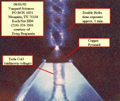
Just curious i have a copper pyramid with the top cut off so it can house a flawless pyramid shaped piece of apopholite crystal, inside the copper casing i have a tunable Tesla coil in the range of 30 000v to 75 000v if i remember correctly…. The weird bit is the ionization effect makes to copper turn transparent when over saturated with ionized state electrons and when the copper casing becomes over saturated the ionized state electrons flow out through the top of the crystal pyramid as a double helix twist of blue light!!!! Althoúgh I’m unsure if the light emitted is electrically charged can you possibly explain why this reaction is occurring and secondly i would like to use the multiplier circuit you guys have described here as a method to regulate the current being used a little better as at the moment I’m using a huge amount of current to generate the optical state electricity(due to inefficient and out dated circuitry your voltage multiplier seems to be the answer to my problems but unsure of how much of a load it will withstand and how long of a continuous will it sustain before the circuit blows i dont know a lot about the subject so please excuse my ignorance……
Here’s a photo from another person who made the same device as myself might help clarify what I’m talking about
Hello, I am building a voltage multiplier with six 470nf/630V caps and 1n4007 diodes using a 220V, 50Hz AC input for a bug zapper. The circuit also includes a 100uf/400V capacitor connected to it to compensate for loss of energy when an insect lands on it for effectiveness. I am trying to build something as safe as possible, so that when the grids are touched by a human, it will only shock but not kill.
I intend using a 33W source (transformer) to power it. Do u think that will be sufficient to drive the circuit? and also if it is safe in the case of human contact with the grids?
Please give me any possible recommendations urgently. Thanx. Great site by the way! Really educative.
Read the DIY page linked at the bottom of the article.
Input is AC.
Output is DC voltage between output and ground. Polarity depends on how you build it.
I want to build a full wave voltage multiplier, but I don’t exactly understand how it works. From the diagram it looks as if there are 2 inputs, but only 1 output.
Is the output positive or negative?
Is the input positive or negative?
Do i need to make 2 of them, 1 for the positive and 1 for the negative?
Help!
Thanks.
too bad iam wait a week
can you help me i cant mack this circuit can i know the value of the component to make voltage multiplier from 220v to 3kv or 5kv iam trying but its not work
I have no idea about the current required to kill an insect. The voltage is high presumably so that it can get through the dry outer shell of the insects.
Pulsing is not important for killing them, but it is usually a product of the way the voltage is stepped up.
this is related to the mosquito zapper question: from previous knowledge or based on the zappers out there….how much current is needed to kill a mosquito? why do these zappers need so much voltage multiplication? is the mosquito resistance that high?…and must the current be a pulse?…do let me know or point me in the right direction to where i can find answers…
Thanks
I is the load current calculated with ohms law.
sir,
i want to ask that from the theoretical formula when we want to calculate the ripple voltage and also voltage drop on load the formula is
∆V_total=q/C n(n+1)/2=I_1/fC n(n+1)/2
δV_total=q/C (2/3 n^3+1/2 n^2-n/6)=I_1/fC (2/3 n^3+n^2/2-n/6)
i want to ask that the current, I use in this 2 formula is how to find out? got any formula use to find I? Or I is the specific given in design a circuit?
A multimeter when set to measure voltage does not require much current. It will work fine.
as the current is low i cannot measure with multimeter. can i use some other detector or something?
You need to make a voltage divider. You can then use your multimeter ant multply the reading by the division ratio.
i have made an ion generator of 6 kilovoltage. i want to measure the voltage? what should i do? i cannot measure with multimeter
I think that some of your diodes or capacitors must be blown or postioned incorrectly.
sir,
my input voltage is 240 volts from the mains. when i measure the voltage from second stage i am getting 600volts but from third stage tge voltage is decreasing to 500 volts.
I think you are getting some sums wrong there. What is your input voltage?
dear sir,
i am making a ion generator with cockroft walton voltage multiplier by using 22n/630V cap. and in4007 diodes…but my circuit is not working.how do i measure output? i am using 24 diodes and caps to generate -8100 volts? is it right? please help me…
hello i built a multiplier (half wave) running off a 680vac psu i used 01uF,2000V 700vac caps and 1N4007 all was working fine with my marx … then today it just stopped working is it possable i have spiked the caps ? nothing happens not even a tingle all is dead (psu is fine) , don’t fancy replacing all the items is all
thanks for all your help re building btw !!
Frank,
You would loose too much power in the conversion process. Anyway, if you step up the voltage, the current goes down proportionally, therefore it will not help you.
mike Okoh,
No, it does not need a transformer, just an AC input.
Vivek,
You can put diodes in series, but it can be unreliable as they wont always switch at exactly the same time. To avoid this place a high ohm resistor in parallel with each diode.
I am using 4 stage voltage multiplier. the input voltage of the multiplier is 50 Kv and the output voltage is 100Kv
I need to design the high voltage diodes used in this multiplier. How can you design the diode which passes 50Kv voltages in it.
I have seen some ultra fast diodes website but i am not really understand it. Do i need to use seires of diodes to genrate one diode?
Thanks
Vivek
Sir,
I want to know if voltage multiplier make use of Transformer? if yes,what type of transformer does it use?and what should be the primary turns and secondary turns of the transformer?
Thanks and God bless you.
Hey,
I am thinking of making a battery powered SSTC (running off mosfets and things). Here is the link for the page:http://stevehv.4hv.org/SSTC6.htm
I want to run it off 12V 7A. I need 12V for the 555 Timer IC, and 50V to drive the Primary. Do you think i should use:
an inverter/DC pulse circuit to drive a transformer
or
a voltage multiplier (for which i would need an inverter)
Would using these methods make the current too low for use?
Thanks 🙂
Sounds like you need a current limiting resistor to preven overload
Dear Sir,
As i have one circuit of mosquito zapper input uses 2AA cells. output 1300V Dc . i am having the problem of
the transformer failure or transistor failure. Is there any protection for transformer & transistor . Kindly provide me the details with circuit. AS in our circuit uses only one transistor 965 & ferrite transformer.
Two stages is a typical voltage doubler. Something is wrong with your simulation.
Hello there, i just built a voltage multiplier(villard) of 2 stages (4 diodes 1n4007 and 4 caps 10nf 1KV , %20 ceramic) with an input of 120v @ 60hz. The problem is that i get only 240v on output… I simulated it on multisim 10 and it measures 675 volts. I dont know what could be wrong. Please help me. Thanks!
No. A voltage multiplier will increase the voltage but the current will be decreased proportionally. There will also be a loss of energy in the conversion process.
What you need to do is to decrease the resistance of your cell by increasing the plate area, adding more plates, or bringing the plates closer together. Ideally your cell should draw too much power when connected directly to a battery. You would then control the gas production rate with a pulse width modulation circuit.
hi sir, i am planning to make a HHO generator, to help me lessen my gasoline consumption, but using 12v battery cant produce enough hydrogen using electrolysis. do i need voltage multiplier to increase electrolysis?
No, That would not increase the voltage.
Hi, I wanted to know if i can just use a full wave rectifier with the AC transformer and hook the caps to it, instead of placing a diode with each cap? Thanks
I want to use a neon sign transformer(15000 volt 30 ma) to feed a cockroft walton cascade to get a negative voltage.
With the NST centre tapped to earth will the output be fully negative or half the voltage below zero.
To whom may concern;
I would like to build DC to DC
converter with input 12V and output 2KV. Any circuit or website that i can refer to?
Thank you and have a nice day.
Best Regards
James Lee
Thank for the help. I would like to bulid my own DC to DC converter with that kind of output. Can you suggest any circuit or web site?
Needs to be AC. You can buy a DC-DC converter fo those sorts of voltage quite cheaply.
The input of the multiplers must be AC?Can i switch to DC input ? As one of my project input is DC12V and output required is 2KV.Or is there another circuit that can generate this kind of voltage?
Thank you!
I tried the resistors but with no luck. I decided to double up the rectifiers to ensure 2KV breakdown. That solved the problem. Thanks & Best Regards, Murray
At the moment the output zaps, it is possible a voltage spike occurs which is larger than the rating of your diodes.
Also all the diodes will have slight differences in timing due to manufacturing tolerances. This could mean that one diode takes most of the current or voltage for a brief moment causing it to blow. Try placing one of your 22M resistors in parallel with each diode to even out any voltage differences.
Hi, I hope you can help me with this problem. I have one of those Tennis Racket electronic bug zappers that runs off 2 C Batteries. The circuit is fairly straight forward. There is a 2 transistor oscillator into a small transformer that produces approx 350 V on the output which then goes through 3 stages of conventional half wave rectification – two capacitors and 2 rectifiers per stage. The chain of 3 stages ends up producing 1500VDC across which is placed a 0.1 Uf cap and a 22M resistor as a load. It works fine for mosquitoes and very small flies but I needed a little more zapping power. So I wired a 0.5Uf 2KV capacitor across the 0.1 Uf cap. I get one or two nice zaps and then one or more of the 6 rectifiers goes short. (All of the caps are rated at 1KV except the output which are 2KV; all of the rectifiers are 1A 1000v 1N4007).
I replaced the rectifiers 3 times and each time one or more of them shorts out after between 1 and 3 discharges. The caps are all fine.
I am assuming that when the cap discharges, the current is very high (>1A for short time). But since the rectifiers are reverse biased I did not think they would be affected. If anything, I would think that the caps might over heat.
Is it possible that the discharge of the output cap is causing the voltage to be unequally distributed across the 3 stages and therefore causing one or more of the rectifiers to breakdown?
Any ideas or suggestions?
Thanks and regards, Murray
More power / higher voltage / current. Optimized electorode design could help too
Hi,,
I’ve mad a negative ionizer, but it’s power is too low, i mean the quantity of air in movement is too low, i want to increase that quantity, any advice ?
Hi sir I am trying to use a half wave multiplier for a RF harvesting experiment with 6 stages and am using the 1N5822 diodes. In the experiment we are trying to recive a 6 MHz signal using the folded dipole antenna. Before connectng the antenna we could receive 0.6 volt peak to peak.but after we connect to our circuit the voltage dips. Is the multiplier shorting or antenna. Can u tell us how to calculatethe dynamic impedance of the multiplier circuit. We are using 10 uF capacitors at each stage. How can we match the impedance of our antenna to the multiplier cicuit??
hi first great site just found today. i try to do a voltage multiplier feeds from a H bridge generate VAC in the order of 12V@50A i need around of 60v@15A and i don’t know how… if a multiplier work to get te current i need? and what would be the most suitable frequency and the value for the capacitors.(formulates)
tks.
Yes, they work well for this.
did you ever use your pulse power modeulator to drive a flyback xmfr?
I have several large old Zenith flybacks with 4,200 turns of AWG # 42 on the secondaries. Should produce 10-15 kV.
Regards,
D.C. Cox
You can find design info an calculationes here.
i have construct he CW multiplier with 23 stage…the input is 240V ac and my desired output is 15kV..there is some problem in selecting the load resistor…can you give any opinion?and what was the main consideration in selecting the resistor?is there any simulation program that i can use to simulate the CW multiplier?
the resistor is on the input..i have change the resistor with 10kohm 10w resistor..thanks for your opinion…
Is the resistor on the input or output? If the resistor is overheating then I would guess you are using one not rated for enough power.
hi there, nice site…i had a question, i need to design a 15kV CW multiplier with 240 ac Voltage input..i used 10nF capacitors and 4007 diodes in 23 stages as calculated..as the current limitation, i use 10kohm resistor..but when i turn ON the circuit, the resistor blown…can u give any opinion why the resistor blown and any suggestion on how to overtake this problem?
The voltage would be increased, the current would be decreased. The frequency component would be lost as it is converted to DC in the process.
Could the voltage (and frequency) output from a generator be elevated using a voltage doubler array? Once brought to the appropriate level, then introduced to a capacitance storage of some type before it’s introduced to a more traditional load? I think the capacitor would not “see” it as a significant load, allowing less loss of power. Possible?
Sorry, no. Why do you want to use a voltage multiplier for your AM?
Hello, im attempting to make an amplitude modulator for an ultrasound signal. Im hoping to use a 60KHz carrier with a 600Hz signal. Ive got a 9V Vcc rail, but that can be changed. Is there any chance you could suggest some values for capacitors and diodes if i were to use this circuit?
Thank you
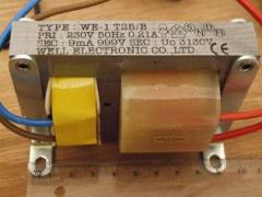
I would think that the 999V is typical RMS voltage at 9mA.
The load impedance ‘seen’ by the transformer varies with time. When the tank capacitor is empty, the load at that instant will be very high. As the capacitor charges the load will decrease and the voltage will rise. Calculate load impedance of a capacitor (reactance) using 1 / (2*pi*f*C).
What does the 999V refer to? The maximum voltage at full load? Is it possible to calculate the load of my tesla coil – I assume that if the load is too high, the voltage will drop too low and the coil will stop working – then start again as the load drops?
Yep, all looks ok to me.
Hello, I’d like to use this transformer as a base for a voltage multiplier. It say Sec: 9 mA 999V Sec Uo 3130V. I assume this means 3130V with no load? I made a voltage divider with 9 4M7 resistors and got 217 V between each resistor-thus 1953 V at that load. Is this correct? I am planning to use three of these to get about 6kV to drive a Tesla coil – will this work? Many thanks Thomas
Your question has been answered already. See the comments on the DIY Voltage multiplier page.
helo! first of all, great site! second of all, I’m not sure how u guys determine the rating of the capacitor and diodes used for voltage multiplier. In my case, Im using 2 fly swatter circuits, i put them in series i get a healthy approx 1400volts.. i want the voltage to be doubled, tripled and so on.. but how do i determine the rating of the diodes and capacitor to be used ? thx =)
Ignition coils are not great for CW multipliers. The output is not DC but it is mostly biased in one direction and not sinusoudal unless is is driven at resonance with a capacitor in parallel with the input.
You should be getting more than 10kV from one of those coils with 18V input. Maybe your driver needs adjusting.
You might be able to feed a CW with two ignition coils in anti-parralel. This would give you a better AC waveform. See comments in the ignition coil driver page for info.
I wish to build a 60kv supply for powder coating. I have 20 20kv diodes and 20 20kv caps. also one of your spark coils which produces about 10kv from a 555 circuit switching a 2n3055 with 18v but as this is pulsed dc it is no help?
how can I best feed a CW stack, 10kv would be nice. Not much current needed only to cope with leakage. Funds limited!
great site very thankful…
Sorry moaza, I was talking to moonrider about the poor English, yours is fine.
The calculations you need go beyond the scope of this article on voltage multipliers i’m afraid.
Simplistically you can calculate the reactance of your inductor by using the formula X = 2pifL.
This is 2 times pi (3.142) times the frequency times the inductance of the coil. This page may help.
this is what am really facing but i’ve recently from a physicist that i should calculate the current in vector manner(he said when ac source is connected to a cap and inductor in series there is a whole different for calculating current i.e.phase must be put in consideration) ,how could i do that?
and is 0.1016 of a Henry enough
by the way am british
The value of the capacitors will determine the max current drawn from the PSU and the peak current when discharging the multiplier.
The last thing you said is not a proper sentence. If your 1st language is English then you need to try harder. If not then I guess it’s fair enough, but I can only answer if you make sense.
would the value of the caps/diodes really matter for example i have 0.1uf caps and 4007 diodes. would this circuit drive a tesla coil? and im guessing that the more caps/ diodes you incorperate the more out put voltage and the more input voltage twice gain on the out.
i have made a variac on my own :
the 1st question : its inductance is 101.6 milliH is this value enough ?
the 2nd :i use i caps beside it as impeders ,& cuz of this am facing a paradox in calculating intensity in the whole circuit and inside the inductor.the calc. current in the circuit is 0.4A while it’s calculated to be 0.002A inside the inductor , how could this be ?
There is usually a capacitor connected in series with the output of CCFL inverters which limits the current. It may also be worth adding a small resistor for protection.
You should direct your query to the manufacturer of the device for further information.
Help with an inverter!
I’m looking at using a BXA 12553 inverter for a HV power supply. The datasheet says output voltage is min 600 V to max 800 V, and output current min 4 mA to max 7 mA. What happens if I try and draw > 7mA (the effective short cct to ground across the uncharged capacitors -> current surge)? And what about when the current draw drops < 4mA during charging? Will the output keep a steady voltage (about 700V) below the rated 4mA min, and can it cope with > 7mA?
We have some high voltage diodes. We often have the caps too, but not at this time. Maybe eBay will have them.
I want to try and build this generator so i went to RadioShack to get parts they don,t have any 15kv or 20kv capacitors and no high voltage diodes where do i get the parts to make this device?
Yes. Any AC supply will work
Could I us my 15000 volt 30 millamp neon sign transformer for input power for a voltage multiplier circuit?
You can’t. Homemade transformer + mains = not safe.
The current is limited by the impedance of the capacitors at the frequency of the input voltage. If you know the impedance, you can use ohms law to calculate current.
how can i grab current from the mains by homemade transformer safely for such a multiplier,and how could i limit the current by caps ,i mean wat impedence should give how much amps
No, this wouldn’t work. You need an AC input for a voltage multiplier. You can buy tiny ones meant for powering cold cathode tube lights inside PC cases. They turn 12 VDC into about 1000V AC. You could then stick a couple of multiplier stages onto that.
hello again
it is ok to make an -ve ion generator without an inverter just voltage multiplier, 12v battery and a neddle?
Google is your friend and Wikipedia has anwers to many basic questions.
what is an inverter? how can i do it?
im very sorry that i have so manyy question because i’m not expert in electrical…
thanks….
thanks….for me it is not bad idea because my porpuse is to perform magic… electrcity can give a nice effect….your site is great… if i will be famous in my place…you are one who help me…hehehehehe
A negative ion generator is just a high voltage DC supply with sharp points or a grating at the output.
It consists of an inverter and a votage multiplier like shown on the DIY voltage multiplier page.
That project just looks like a bad idea as you are likley to hurt yourself or others.
hi
i want to build negative ion generator
i only have little knowledge in electricity can you make an instruction how to make a 12v dc negative ion generator.. i want the many -ve ions produced… my porpuse is to make an pika shoes found in this link (http://afrotechmods.com/cheap/negativeiongenerator/pikashoe7.htm)
i hope you will reply…thanks
Bulle:
The output Voltage of a multiplier drops off quickly with current drawn. If your load is constant then you coul possibly use a voltage divider and a few sums.
Mike:
It depends on the components you use to make it. Use big capacitors for bigger current.
How much current can a 10x full rectified voltage multiple circuit delivery on the final output stage?
Hi there,
Can someone tell me if there is a good way to measure the current from a half wave CW multiplier? the output is about 30kV and I want to measure the current to regulate an SG3524 chip.
Best regards,
Erwin
It doesn’t have to be. Can you describe what you mean by smoothing capacitance and the 1st capacitance, I’m not sure I understand your question.
Iam designing multistage DC generator to produce 10kV,1mA,and ripple factor of 5%,it has an input of 2kV.Ive already found out it has two stages. My question is why is it that the value of the first capacitance has to be twise the smoothing capacitance?
larger capacitors will provide more smoothing.
For an ideal voltage multiplier…
V(out) = 2 x NumberOfStages x PeakInputVoltage
..but this does not account for the voltage drop across each diode, so you could end up with much less. The output voltage will also drop proprtionaly to the load on it.
You can find more detailed info and calculations on this page.
Hi there
I am designing multistage DC generator to produce 10kV,1mA,and ripple factor of 5%,my questions are how do u come with the values of capacitors,the output from the transformer is 1kv,since the output for every stage is 2nV,does it mean i need to have 5 stages?
I have built several ionizers from 4007 diodes and 4.7 uF electrolytics. It is not required to use isolation x former. Just limit current surge at mains. Also, fuse is good to include. Don’t for get current limit at top too!
Whole idea of using multiplier is to avoid xformer!
You can make a multiplier run directly from the mains, but I would reccommend using a transformer inbetween the mains and the multiplier circuit. This would limit the current and thefore reduce the chance of seriously dangerous power levels on your circuit.
You could either use a step up transformer so you would need less multiplier stages, or you could just use a small isolation transformer to limit the current available.
I was thinking of making some Ozone, like this… http://www.emanator.demon.co.uk/bigclive/ozone.htm using two meshes at either side of a piece of glass.
Could I use something as simple as this, attached to the mains (240V) to get the voltage I require? (say, 5-7kV). I’m trying to do it as simply as possible.
Great site, by the way, just discovered it today. I’ll be back!
-mu
A voltage divider is usually made from just resistors. Sometimes capacitors are also used. Diodes and valves are not used unless you need to switch or rectify the current.
You can learn more about a voltage divider in the electronics section.
Dear Sir,
I am woundering how would be posible to build a voltage divider with diods and capacitors or may be with vacuum tubes.?
Thanx
alhege@hotmail.com
Li Yun Lim,
There is a response to your enquiry on the DIY Voltage Multiplyer Page.
Dear Sir/Madam,
I am designing a voltage multiplier circuit. I started off by building a 2-stage half wave voltage multiplier circuit using NTE517 (5kV) diodes and 1000pF (15kV) capacitors. I connect the circuit to a variable transformer and tuned the variable transformer to 10Vac. My result for my 1st stage is 5.57Vdc and 2nd stage is 3.72Vdc. Why is it that the output voltage is decreased? Are the types of diodes and capacitors used unsuitable? Could you recommend me a suitable type and value of diodes and capacitors?
Thank you.
Ohh! I think it works! I forgot to connect also the ground terminal. When I did that, I got a little spark (only 6 stages). Very good.
Thank you!
Hi, It is hard to say what is wrong with your device. I can’t see from your photos how your circuit is configured.
If you would like to post larger images, please use the forum.
I could guess that either the components are not connected correctly or that they have been damaged.
If you are connecting this multiplier directly to the mains then it is posible that your diodes are blown. Normally something such as an isolation transformer would used to limit the current flowing from the mains.
Without any current limiting its possible that the diodes were exposed to a surge current beyond what they can tollerate. This happens because the uncharged capacitors will briefly draw a large current when the device is first connected to the mains supply.
The second photo.
Hello! I’ve seen in the web voltage multipliers with for example 15 or 20 stages, so you can connect to 220 V and get about a few kV (ionizer for example). I tried with six stages to start with typical 1N4007 diodes and capacitors of 47 nF and 400 V, but in my case at the second stage the voltage starts to decrease and in the sixth stage I only have a hundred of volts. What’s the problem? Can you help me? It’s better to have a input with many volts or it doesn’t matter for the voltage drop along the cascade.
First of all you will need some sort of inverter. This will convert the 9V DC to a Higher voltage AC
There are many of these circuits available used for powering flourecent tubes or cold cathodes.
Each stage of the voltage multiplier will theoretically double the input voltage. A nice Small inverter that will fun on 9VDC is the cold cathode power supply shown in the High voltage section of our shop. this outputs about 800V from a 9V battery, so adding three multiplyer stages would give you about 2400V.
If you have further questions, you can use the forum, as it will send you an email when you recieve a reply.
You can also find more information in the DIY Voltage Multiplier section.
Hi! I wanted to know how many steps would i need to make a multiplier to convert 9V DC to about 2kV DC. what components would i require other than capacitors and diodes.
*urgent…reply soon*