Contact Electrification
Contact Electrification
 Contact electrification is the process where two dissimilar materials are touched together, and then separated, causing charged particles (electrons) to be released as bonds are broken between molecules of the two materials. A simple example of this is rubbing a balloon on your clothes so that the balloon becomes charged and is able to attract small particles or stick to walls.
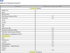
The triboelectric series is used to show how well some common materials will absorb, or give up the ‘free’ electrons within them, and therefore becoming negatively or positively charged respectively. The table below shows how some materials become charged relative to each other, from most positive to most negative. The ability of the material to hold this charge is mainly dependent on the humidity of the surrounding air and the smoothness of the material. For example; a balloon will hold it charge for much longer than some fur because the individual points (the hairs) of the fur will cause corona discharge.
The Triboelectric Series
| Material | ||
| Most Positive | Dry Human Skin | Most Positive |
| Leather | ||
| Rabbit Fur | ||
| Glass | ||
| Human Hair | ||
| Nylon | ||
| Wool | ||
| Lead | ||
| Cat Fur | ||
| Silk | ||
| Aluminium | ||
| Paper | ||
| Cotton | ||
| Steel | ||
| Wood | ||
| Amber | ||
| Hard Rubber | ||
| Nickel/Copper | ||
| Brass/Silver | ||
| Gold/Platinum | ||
| Polyester | ||
| Styrene (Styrofoam) | ||
| Saran Wrap | ||
| Polyurethane | ||
| Polyethylene | ||
| Polypropylene | ||
| Vinyl (PVC) | ||
| Silicon | ||
| – Most Negative – | Teflon | – Most Negative – |
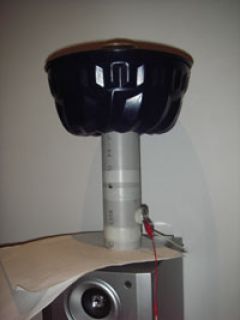
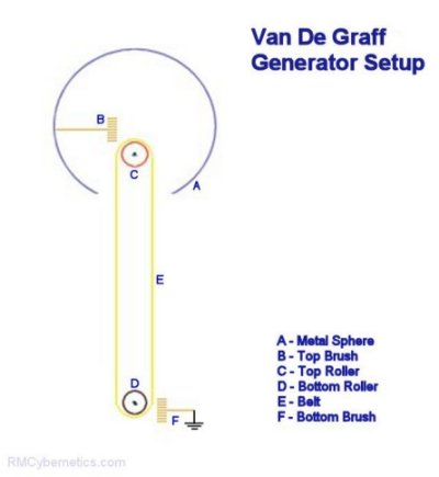 There are a number of devices that utilise contact electrification. A popular device is the Van De Graff Generator as it is very simple to construct. This device will produce very high voltage electricity at very low current. This means that they can be safe to touch, although it may make your hair stand on end! It works by using two rollers and a belt made from dissimilar materials. As the belt rotates, charge separation will continually occur at the point where the belt moves away from each roller. If a metal brush is placed near to these points then the charge can be collected or deposited. The choice of belt and roller materials will determine the polarity of the voltage produced.
If a sharp point (a pin) is placed on the output of a Van De Graff generator, voltage multiplier, or other High voltage DC supply, it is easily possible to witness an interesting effect. This effect is often referred to as ‘thread like streams of charged air’ Logic might suggest the ion wind should spew out in all directions (because the like charges repel each other) from the tip of the pin towards objects of opposite charge. Under the right conditions the ion wind will come out as a fine thread from the tip of the pin. This seems to contradict the idea that these charged air molecules should repel each other.
High voltage electric fields seem to be the key to unlocking some of the deepest mysteries of the universe. There are may reports of anomalies when experimenting with high voltages. For more information on the weird science, see the unexplained section.
55 Comments
Leave a Reply
You must be logged in to post a comment.
Latex works well, some belts are treated for UV resistance. We have some belts in the shop.
VDG Belts
Aww Bummer, I thought the thicker belt would be great because the uv would not wear it out as much, but I wasn’t thinking about it making it harder for the electrons to be attracted.
So what is a good belt material?
I have had trouble with this part for a long time and havn’t really found any satisfactory answers.
What are a couple of options for rubber material, and what is the best rubber for a VDG belt? Also about how thick should it be? Thank you very much, Jason
The rubber should also become charged. The EPDM rubber possibly contains carbon making it conductive which would make it not useful.
The metal pin is ok as you can link it electrically to earth. Make sure your motor casing is also earthed.
4mm belt thickness is probably going to significantly impair the efficiency of your system. You might want to consider something different.
Hello, I am workng on a Van de Graaf generator and I was wondering if EPDM rubber will work good for the belt material. I am using a teflon lower roller and a glass upper roller. I tried rubbing the teflon roller with a piece of EPDM rubber and the teflon roller would attract small pieces of dirt and dust, but the rubber would not. Is this a good sign? I also rubbed the teflon roller with a different type of rubber, and both the roller and rubber would attract small pieces of dirt and dust. Which reaction is better for a VDG belt? Also the teflon roller is a tube made of teflon with a piece of pvc pipe inside, this then slides over my motor shaft, and in order to prevent slippage I drilled a hole through the teflon tube, PVC pipe, and the motor shaft and inserted a steel pin through the holes. Will this prevent or harm the teflon roller from becoming charged, I am concerned that the charge may leak from the roller through the metal pin to the motor. Also 1 more question, I am now wondering if my belt is to thick, I know that the thicker it is the longer it will last. My belt is 5/32” thick, is this to thick? Will the roller still be able to attract electrons through the belt if this thick?
Thank you very much for help.
Well look at the table above. There are metals in various places between dielectrics.
if it is not related why do you think they wil cumout wif tis tribo series?? this is what i found in google book. can i say that the greater the dielectric difference the greater the static cling will be??
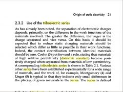
No, it is not related to dielectric constant.
is the triboelectric series arranged according to their dielectric constant value? that is from the highest to the lowest? which means high dielectric constant become positively charged and vice versa.
Ok. Thank you very much. That is what I had assumed, but my teacher was making it much more confusing….
Thanks again!
Der Strom
The triboelectric series is a relative chart of how easily some materials may gain or give up electrons. Rabbit fur is shown as positive because it will easily give up electrons to any material below it in the series. Rubber is shown as negative because it will steal electrons from other materials that are higher in the series.
Any of the materials can be made to be positive or negatively charged. It just depends if the other contact material is above or below it in the series.
Ok, so I’ve been in the middle of a sort of argument in my physics class. I’m hoping you can settle it for me:
We know that if a rubber balloon is rubbed with rabbit fur, the balloon becomes negatively charged. Therefore, the rubber must have gained electrons from the fur. The problem is, however, that according to the triboelectric series, rabbit fur is positively charged. If it’s positive, then why would it lose electrons to the rubber?
Thanks for your help!
Der Strom
You just need to use better materials to build it with. Use some sort of bearings for on the rotors so that the friction is reduced.
Also, the speed does not need to be fast. If it is melting, that probably indicates that the motor is running too fast.
hi, i am making a vdg which is my first until now for my scince exb. so i really want it to be the best , abt the vdg made the belt out of 2 layers the outer layer is fabricsilk and and the inner layer of tents belts( ones with large surface area) the spinners (i used painting rollers) upper coverd with ALumi. foil and the lower coverd with tape and the support tubbing is 1M long and 6inch width and used a seawing mach. motor ,and for upper brush (used clothing metal hock)bended in triangular shape and hanged down a wiring (without insulation) and made it touch the sphere , the sphere of 2 bowls 9inch width by 5inchs , my problems are that sound factor(too high!)and the axes of lower roller is melting the PVC pipe and couldnt find a way to build the lower-brush plz help (sorry 4 writthing an S A)
Oops. Sorry. I mean a piece of ALUMINUM wrapped in leather.
Ok. I’ve changed my plans just a little bit for my VDG. I have an old vacuum cleaner motor, which I will have attached to the bottom roller, which is made out of brass covered in teflon tape. I will use a strip of vinyl for the belt, and the top roller is made out of a piece of steel wrapped in leather. Pictures soon.
That will work. If you decide to experiment with different materials, remember it is just the contacting surface that needs to be changed. You can simply wrap a sheet of a new material around your existing rollers.
So I have a hunk of aluminum for the bottom roller, vinyl for the belt, but could I also use PVC (~vinyl) for the upper roller, or does it have to be a completely different material from the belt?
Thanks again!
–Der Strom–
Yes it would work, you can use any two materials, the further from eachother on the table above, the better.
I have an old vinyl bed sheet, and I was wondering if it would work as a belt for a large VDG. If so, what materials should I use for the rollers?
Thanks!
–Der Strom
No, This wont work.
Do any one think if we use two metal rollers in a van de graff generater with +ve and -ve terminals of dc adopter attached to. Then we won’t to use glass or plastic.
i made a smal VDG about a year ago, stole a baking tin off mum for a sphere, i was getting 12cm spark jumps off it. you could smell the ozone being produced by it too
Ye Gods! Just followed the `Flanker` thread. You deserve V.C. + Nobel Prize for A)Keeping a straight face; B) Staying sane; C) Simply not telling him to `go` The guy is thick, he`ll kill himself. Regards. W.B.
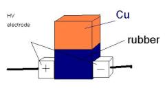
Not exactly. The dipole moment would be an induced one rather than a permanent one caused by the molecular structure of the material its self.
Dielectrics also have a very small level of conductivity so any induced voltage would leak away eventually.
Man made electrets are often formed by setting a liquid compound in the presence of a high electric field. This way the molecules align to the field and set into position when it hardens.
i mean this permenant charge as i understood should be between the two sides of the material making a positive and a negative pole as a magnet but with an electric field , could this be achieved from fusing a dielectric between two of those different materials after getting them charged, if i misunderstand the whole matter or am i right
The electret effect is actually quite different as it is a quasi-permanent dipole moment in the charge distribution in a material. Contact electrification involves the making and breaking of ionic bonds between dissimilar materials. Maybe a tiny amount of contact electrification could occur from air hitting another material. Collecting it would probably be done with something similar to an electrohydrodynamic thruster.
this subject over here is quite simillar to the electret effect,could the using of two different material of those (incontact with each other) produce the alleged “free energy” from ionic air molecule (+ve ones)and how this plane could be connected to the ground to charge a cap.
would be finer if with drawing
I can’t really help you any more on this I’m afraid. This section really is for questions on the page subject of ‘Contact Electrification’.
I simply can not continue to provide help for free for your own personal projects. I can design whatever electronic systems you desire, but you must pay for the time and resources. See the Custom Electronics page for details.
am sorry for bothering u too much, but i do cuz i really think that u could help me cuz this electrolytic rection is being set for a patent,
this reaction is at a voltage range of 1-1.2volts
and never mind of the intensity
as long as it’s constant, the power may range from 250-12.5w according to the power supply am using,according to the latter info can u help me in any specifications of the regulator used.
really appriciating ur help wether u can find this one or not
This is what a voltage regulator will do. It keeps the voltage at a set level regardless of the resistance of the load (your electrolyte).
If you want to maintain a constant rate of reaction then it is actually the current you will need to regulate. Devices for this are often called ‘constant current diode’
i succeeded in wat i formerly assumed for voltage dividing , but i noticed that as the reaction proceeds forward the resistance of the electrolyte shifts in a considerable way , so the voltage values changes , if i dont want to watch the meters all the time and to sit on the pot. wat can i use , recommend wat to fix the voltage at a certain level for a power not less than 15watts
There are thousands of different types. You will need to refer to the manufacturers datasheet for for instructions.
Google ‘adjustable voltage regulator’ for some examples.
This L200 regulator may work for you. The datasheet also includes example schematics.
am sorry but this may be only the second time i hear about IC Vregulator,how should i connect it and how to use the variable resistance with it.
wat intervals of power does it operate on ?
thanks
Use a voltage regulator IC. They are low cost and will deliver a reasonable level of power.
Most voltage regulators are set to a specific voltage, but you can also get adjustable ones where you could use your low power pot to adjust its output.
hi
am running an electrolyte and i have to pass only a certain voltage through it ,i have tried to make a voltage divider but the pot. got burnt cuz of the high power ,and high power pot.s are expensive here , could i connect in series a low current pot with a high wattage (about 10 ohms) common resistance to dec the power load on the variable resistance or wat should i do ?
very thankful
This supplier of high voltage relays makes a nice range of large HV relays.
You can caluclate the watage of your resistors using Ohms/Watts law. Using the square of the voltage across each resistor divided by its resistance will give you the minimum power rating needed.
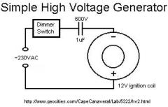
The opposite side of the secondry winding of an ignition coil is internally connected to the -ve input termainal. You can take your HV output from between this and the output terminal.
could i use sorta a huge massive efficient relay
as the high voltage switch and if i can please recommend me a particular one
if am making a voltage divider for high voltage source , wat should be the wattage of the resistances
in the dimmer circuit shown above from where should i get the ground for the high voltage output,i think of using the water tab cuz ofcourse it is AC which is going on the 2 primary coil terminals so i can use neither of them, can i ?
and thanks much
Maybe a piezoelectric transducer is what you need. You could place the magnet onto something like this cymatics device which is used for making faraday waves.
Hi, wow, nice site!
i have a question:
How is it possible to make a permanent magnet vibrate, i’ve read that a pieso-something can work, i’m trying to replicate a certain experiment of faraday i think,
thanks in advance
keep up the imaginations raving
Making a wheel from the dielectric with several copper pieces embedded in it would make a good rotary type switch.
The current flowing from your charging supply will drop to near zero when the capacitor is charged. You could use an ammeter to indicate this.
The 2M resistors only need a low wattage rating because they are just being used to distribute the voltage and not much power. The typical 1/4 watt ones would be fine.
sorry ..
just forgot to ask another question :
when charging the HV Cap. by the talked about diodes series how can i know when exactly is the cap voltage is equal to the source voltage (i.e:the cap is full or almost full)
can i attach a LED in sorta way or there is someother way
sorry again about the 2Mohms resistors wat is their wattage.
peace..
i have uploaded it on the following link “http://img263.imageshack.us/img263/1273/sparkyx0.jpg” as i think it will fail again in being forwarded.
the idea is to move swiftly and very rapidly the intermediate part up/down for switching , but am still thinkin about such an efficient way of movement ,Almst the same idea of obstacling by a magnet and movin it as u formerly recommended
The diodes will not all work at the exact same time. This can lead to an uneven voltage distribution between the diodes which can cause then to fail. You can get around this problem by adding about 2M ohm resistor in parallel with each diode.
Measuring the output would be more accurate ad easier.
Can you draw a diagram of your HV switch?
hi
can i half-wave rectify high AC voltage simply with a series of 1N4007
by the condition that every single diode adds a back-blockage of 1000 volts and all of them can pass a current less than 0.7 Amp
when measuring the outputs of the dimmer’s circuit can i simply calculate it or i only have got to use a current divider and a voltage divider and a simple multimeter
about the hi voltage switch i talked about before it is a continuous cuboidal shape consisting of two equal cubes of a bad conductor and a good conductor fused together and it is moved swiftly between the high voltage electrodes.hope u can imagine it.
if it’s beginning to be hard to bear u just can say it cuz am feeling so …
Photodiodes are usually used with signal level currents. Other types of diodes will be expensive if they are to withstand a large current pulse from the discharging of a capacitor.
It is possible to wrap a few turns of wire around the case of an ignition coil to be used as feedback for a flyback driver.
the 2n3055 is rated for a maximum of 15A.
peace
am now searching as u asked for but i found some interesting results as avalanche diodes (can hold up to 4kV) (could many of it be connected in series and operated “on” by an external cap of about 1kV in series) and avalanche-photodiodes wat about them ?also wat about zener breakdown ?
or could i directly force the main cap to arc by the same way and after the first arc there wouldn’t be enuf energy for arcing back in the LC and it would continue to resonate
but i didn’t find much about VBreakdown tables
However,can’t the ignition coil be driven by resonance as does the TV flyback by winding a 2nd primary to the transistor’s base-emitter circuit coil from around its exterior.(operating on a DC)
recently have fixed and modified a puffed up PC powersupply and turned it into a lab PS
it’s terminals go as follows: 5V/8A , -5V/8A , 12V/20A & -12V/30A
could the 2N3055 power-transistor be powered upon these terminals & their combinations or it would just get burned(can their be Rs to prevent so) ,(would be marvellous if u have its fact sheet)
really without a bit of hipocracy ,i swear am very thankful to a massive extent ,really can’t describe it
u’r just sophisticated
peace again … by the way wat can i call u
Klystrons, magnetrons are generally used for microwave amplification. They are vacuum devices like the old style ‘valves’ that were used in radios. A amgnetron can be found in a microwave oven. It is used as a resonant cavity for generating the microwaves. None of these devices would suit your application.
A dimmer will work with an ac input. You would need a pulse width modulator for DC.
Google will adequatley answer your last question. Use “breakdown voltages of dielectrics”. There’s plenty of useful data there.
how u doin
i have read an article about high voltage discarging and there were mentioned about the high voltage switch that “magnetrons” ,”klystrons” & “vircators” can be used
r those things applicable for me and how can i get make or use them (and how does they work in the first place)
about the commercial dimmer shown previously in the image -could it be used with dc input or it just works with ac
also i would be very thankful if u could give me a link or so to a site where i can fine about the breakdown voltages of substance (for the capacitpr ofcourse)
really appreciate u
A dimmer switch works by ‘chopping’ the current flowing through light bulb. It basically switches the light repeatedly on and off at a fixed frequency. When you turn the switch (a potentiometer) the ratio of on time to off time is changed. To make the light brighter you increase the on time therefore increasing the average power. This is known as pulse width modulation.
The rate at which you will be able to discharge your capacitor will mainly be determined by the inductive reactance of your system. You will need to keep wires as short, wide and straight as possible. The same for the capacitor. Use large conductors with as few bends as possible.
Most questions are answered by me but some are answered by other scientists if they can provde a better answer.
first here is my idea but put in ur mind am an amateur in the first place
may peace be upon u
i have concluded that in the first place it does need very fast mechanical displacement wether using a magnet or my damn design , it is how fast the opposithion will decay to let the current grow , so we must start thinkin in the light of this ( iam waiting ur ideas )
i wanted to show u this image
it would be massive for ur plasma globe u formerly offered on the site the capacitor’s impedance should be about 3000 ohms
but my problem in this design that where i live the dimmer switch is very expensive and am askin u for an alternative that i can make or cheap to buy ( cuz i donno how does the dimmer really work) i just know it is a sorta variable “power”inputter or so .
the whole thing about the spark gap is that a making a super capacitor and i want it to discharge so fast in nano seconds for a very powerful metal propeller …. so far i have chosen PET for the design dielectric cuz its (C*breakdown voltage) is very high about 22000 , if u can recommend me a better one please do
r u only one engineer who answer all the forums or wat cuz if u r so u must be a genius
waitin ur response
If you could describe your application I may be able to help better.
You can’t really do a lot change the resistance of the spark gap because it is just a product of the voltage, spacing, and air/gas mix. You could possibly change the gas to Argon for example, but this has lower ionization voltage so the switching would be less abrupt. Another way would be to reduce the pressure inside the gap.
I don’t know how you might calculate the resistance, but it will be a dynamic (changing) value. When the arc is fully formed, the resistance will be very low.
Are you describing some sort of rotary spark gap here? Insulating the spark gap electrodes will reduce leakage and allow you to trigger the spark manually (when you remove the insulation) rather than when the breakdown voltage of the air gap is reached.
One method of improving spark gap performance is to use magnetic quenching. This is where strong magnets are placed either side of the gap so the magnetic field crosses at 90 degrees to the electric field. With this setup, the arc will be pushed outward as soon as it forms. This is because when the current begins to flow it creates a magnetic field which will react against the field from the magnets. This has the effect of switching off your spark gap very quickly.
how u doin (by the way i love u)
i wanted to ask some questions about the spark gap (we talked about formerly)
just some trivial ideas wanna know if they could work or not
could applying a steady capacitive dc field from an external cicuit to the spark gap decrease its resitivity for the HV impulse
how could i calculate the spark gap resistivity
what about presetting of a very isolating material(ensures close distance) going continuous with a metal or so and moved perpindicularly very quickly in the field
instead of the air and the metallic ball offered in this side, it could be a rectangulare piece of plastic continuous with a very good conductor
very thankful for u after all
You would use an SCR in a similar way to how the MOSFET is wired in the pulse controller circuit. The main difference is that an SCR will not switch off until the voltage drops to zero.
If you want to switch 20-30kV with a silicon device like an SCR, you will find that this can be quite expensive. This is why a spark gap is used in most Tesla Coils.
i may seem stupid 2 ask such questions here but this is the only way i found inorder to contact u as ur answers r marvellous
– first i want to make a high voltage switch (about 20-30kv) without time delay or much time-energy consumption of the pulse discharged
– i have read the subject about the ignition coil driver i find it money consuming compared with a capacitor – SCR pulsator connected ot the primary – the question is how to connect them (the cap.& scr)
please please if u can’t answer me here forward it to “thechaosdrone@yahoo.com”
please