Electronic Components
Electronic Components
This page details some of the most common electronic components and the symbols used to represent them in a circuit. The symbols used can vary between types and around the world so we are just showing you the most common ones. If you are new to this subject we recommend you read the previous page first as it explains some of the terminology used on this page.
Resistor
 A resistor is a simple component that is deliberately made to be a poor conductor of electricity. The amount of resistance the component has can be chosen when they are purchased and is measured in Ohms. They are used in a circuit to limit the current flowing in part of a circuit or to allow voltage to be controlled in a specific way. Resistors can be made from numerous materials.
Variable Resistor (Potentiometer)
 This is similar to a standard resistor except it has an extra terminal. By twisting a dial or moving a slider the resistance can be varied. It is simply moving the point of contact on the resistive material which effectively changes the length of material between two contacts. They are often used for volume control in audio circuits by varying the voltage to another component.
Capacitor
 A capacitor simply consists of two metal plates separated by an insulating material known as the dielectric. There are many types available such as ceramic, mylar or electrolytic. These terms all refer to they type of dielectric used as each has its own advantages and disadvantages. A capacitor is essentially an energy storage device. The amount of energy that can be stored in a capacitor is related to its capacitance, measured in Farads, and the voltage across it. They can be used to store energy and then release it in a large burst of current. When a capacitor is connected to a DC source a current will begin to flow as electrons build up on one plate, and are removed from the opposite plate. The current quickly diminishes as the capacitor becomes ‘charged’. This is because the voltage across the capacitor is now the same as that of the source. This effect is used in circuits to block DC.
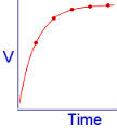 This graph shows how the voltage rises across a capacitor as it is being charged. The amount of charge overall in the capacitor is always the same as it is simply moved from one plate to another.
The first electrical experiments often involved high voltage DC or static electricity. Electrical energy was stored in capacitor like devices known as Leyden Jars. Later capacitors were similar to what we use today but were known as Condensers.
Capacitors are not just used to store energy. They can perform several different functions when used in AC circuits. Capacitors were quite mysterious to scientists and engineers who were first experimenting with AC electricity. They could supply electrical power to a device such as a light bulb, even though there was a gap or an insulator (dielectric) in the circuit. This seemed strange as they had no knowledge of electrons and the way electrical current flowed.
We now call this effect Capacitive Coupling. This effect only works well when the AC frequency is high enough so that the capacitor is constantly being charged one way and then the other. This means that an AC current is able to flow throughout the circuit. Capacitive coupling can also occur between an AC circuit and other separate conductors. It occurs because of the way the electrons in the circuit will interact with the electrons on a nearby conductor. As the electrons in the circuit move around they will cause nearby electrons to move around due to the repulsive force between them. This can sometimes cause undesirable losses in a circuit as energy is transferred to the nearby conductor.
The resistance to the flow of an AC current of a set frequency is determined by the capacitance of the capacitor. This is also measured in ohms but is called Impendence. At very high frequencies a capacitor will put up only a small impendence, whereas at low frequency or DC the impedance is high. This effect is used in circuits to allow AC signals to pass through whilst blocking off DC current. It can also be used to filter out or tune into a specific frequency.
In an AC circuit capacitors can be used to alter the phase relationship between the voltage and the current. When the capacitor is uncharged the voltage across it is zero. This means that the maximum current can flow from the power source. As the capacitor charges up the voltage across it increases, which ‘pushes back’ against the source therefore reducing the current flow. When the voltage across the capacitor is maximum, the current flow will be at minimum. We call this out of phase because if we plotted the current and voltage on a graph the current would be 90 degrees ahead of the voltage.
Inductor
 An inductor in its most simple form is a coil of wire similar to that of a solenoid. These components can be used in similar ways to the capacitor but with a few major difference. An inductor works in the opposite way to a capacitor for several reasons. It allows DC or low frequency current to pass through it more easily than high frequency. This occurs because an inductor resists changes in the current flow.
It can be useful to imagine the DC current flowing in an inductor is carrying lots of momentum, like water flowing in a pipe. A continuous (or DC) flow of water will not feel much resistance, but if we suddenly try to change direction, the momentum in the water will make it quite difficult as the water must be slowed down and stopped before it will reverse.
In AC circuits the phase relationship between voltage and current is opposite to that of a capacitor. When a voltage is first supplied to an inductor, it will resist the change. This means that the voltage measured across it would be maximum, but there would be minimal current flowing through it. As the current begins to flow, the voltage across the inductor will fall until it is very nearly zero, and at this point the current flow will be maximum. If we plotted the current and voltage on a graph, we would see that the current lagged the voltage by 90 degrees.
The flowing current in the coil or inductor creates a magnetic field around it. Potential energy is stored in this magnetic field, and is released if the power source is cut. Switching off the power source will cause the magnetic field to collapse as the ‘momentum’ of the electric current diminishes. When a magnetic field changes near a conductor a current flow is induced in it (see Electromagnetism). It is this self inductance in the inductor that tries to keep the current flowing in the same direction.
Transformer
 Transformers come in several different forms. The simplest one consists of two inductors (coils) wound around the same iron coil. The coils are electrically insulated from each other, but the changing magnetic field in the iron core is used to transfer energy between them. The two coils are known as primary and secondary coils. The primary coil receives the AC input such as the mains, and the secondary coil outputs the altered current.
In a standard transformer (like used in most mains powered devices) the number of turns of wire in each of the two coils is different. The ratio between the number of turns determines how the current and voltage will be changed by it. Most electronic devices only require a low voltage to run so a transformer is used to step down the voltage from the mains supply. In this case the primary coil will have a large number of turns compared to the turns of the secondary coil. If we wanted a 12V output from a mains supply of 240 Volts then the turns ratio must be 240:12 = 20:1. This means for each turn on the secondary coil there must be 20 turns on the primary. The total number of turns only effects the efficiency of the transformer, as it is the ratio which determine the voltage and current change.
In this example the voltage is stepped down 20 times, which would mean that the current would be stepped up 20 times. In real transformers, lots of turns are used on each side so that the current available is limited to safe levels.
Diode
 A diode is a device made from layers of semiconductors like silicon. It acts like a ‘one way valve’ for electric current. These are ideal for converting AC currents from transformers into DC for many things such as charging batteries. Special arrangements of diodes can be used to perform other useful functions when combined with other components such as capacitors, as seen in a typical Voltage Multiplier. The arrow like symbol indicates the direction which current can flow through the device.
Transistors and other Semiconductor devices
There are many types of transistor type devices available. The most common ones are shown below. Transistors are used to control currents in a circuit. They are great for amplifiers as you can control a large current with a relatively small input signal.
Bipolar Transistor (NPN)
 This is the ‘standard’ transistor which is used for many different things. This type is usually used as a type of switch or for providing amplification in circuits. NPN just represents the layers of silicon in the device (Negative Positive Negative). The connecting pins on this transistor are Base (b) Collector (c), and Emitter (e). The path between the collector and emitter is very similar to the diode except it only conducts when there is a current entering the base terminal.
The emitter is usually connected to -ve or ground while the collector is often connected to +ve via a component such as a speaker. If a small voltage is applied to the base terminal a current will flow through the transistor and out at the emitter. This small flow of current ‘activates’ the transistor and allows a larger current to flow from the collector. If the small input signal on the base pin is oscillated the current through the collector/emitter will oscillate in the exact same way. In this example it would cause the speaker to make a sound with the same frequency as the small input signal.
Bipolar Transistor (PNP)
 This transistor is very similar to the NPN type except this new configuration of the silicon makes it work a little differently. This is often used as a type of ‘inverting amplifier’ because the response of the transistor to the base current is the opposite to that of a NPN type. This type of transistor will allow the main current to flow from the collector to emitter when a small current flows out of the base pin. Grounding the base pin switches it on whereas applying a +ve voltage will switch it off.
FET
 FET stands for ‘Field Effect Transistor’. The function of this type of transistor is the same as the NPN type except that the way it provides this function is slightly different. Instead of responding to the flow of current in the base (like in the NPN or PNP types), this device responds directly to the applied voltage. The terminals in this device are labeled as Gate (g), Source (s), and Drain (d) and are equivalent of the c,b,e terminals described above. It is the electric field at the silicon junction in the device which changes the main current flow. This gives it the advantage of being able to respond to voltage sources without the need to draw a current from them. The gate in a FET is not part of the rest of the circuit so it can also serve to provide some isolation between parts.
MOSFET
 MOSFET stands for ‘Metal Oxide Semiconductor Field Effect Transistor’. The ‘Metal Oxide’ part is actually a little out of date as they are more commonly made using polycrystalline silicon, but the term MOSFET is used to describe both types. This is the most common type of FET found in many electronic devices today. It works just like the FET but has more capacitance due to the extra MOS insulation.
IGBT
 IGBT stands for ‘Insulated Gate Bipolar Transistor’. This type of device combines the properties of the MOSFET with those of the bipolar transistor. This allows it to have the advantage of the simple MOSFET gate whilst being able to handle large currents bipolar types. Very large IGBT’s are often used for high power switching as they can be used to control kilovolts delivering kiloamps of surge current.
Thyristor (SCR)
 A thyristor is related to the diode but this device needs to be triggered before any current will flow. When a voltage is applied to the gate (g) terminal the device is activated, and a current can flow. The current will continue to flow even when the voltage is removed from the gate terminal. The device is only reset when the main current flow stops or drops below a threshold value.
Diac
 DIAC stands for ‘DIode for Alternating Current’. This device is a bidirectional trigger diode which will allow current to flow when the applied voltage exceeds its threshold value. Once the Diac is conducting it will remain that way until the current drops below another threshold value.
Triac
 TRIAC stands for ‘TRIode for Alternating Current’. This device is equivalent to two thyristors connected in anti-parralel. It works exactly like a Thyristor except that it allows an alternating current (AC) to flow when triggered. It can also be triggered by a positive or negative voltage.
Next Page: Making Circuits
Previous Page: Volts, Amps and Watts
17 Comments
Leave a Reply
You must be logged in to post a comment.
Ive just found your site and have spend days milling through the data stream… Its a one in a million… Im doing a complete thesis and project from gravity and Stem cells through to perpetual cyberdyne fuel for a pure Earth metalic influence and will put a strong link for you guys on my site when it goes up… Ive got the cure for everything and the greatest rocket designs for Hydrogen that could ground Roger scramjet himself… Im
brushing up on my electronics today so ill be in the Circuit board room for a good while… Well done for the mega ton load of info youve novated… Ill be in contact ASANeeded with questions… probably timing circuit related t a guess… DraX Out… God Bless… … … Crystals Clear … …. …EVENT-UALY …
Herr McGelb,
A choke is simply an inductor with the specific purpose of blocking some AC current.
An inductor opposes a changing current, the faster the change, the more it reacts against it. Having more turns of wire (regardless of wire thickness) means that there is more inductance.
Buy having a higher inductance, it is harder for higher frequencies to pass through. To better protect your transformer, you might want to use a filter which would use capacitors too. A Terry filter is quite popular.
A’tuin,
Tap water is far from dielectric. To calculate the capacitance of your device you need to know the dielectric constant of the water. Please don’t expect me to do the sums for your personal project. Google is your friend.
The winding of a coil to match is more complicated than just a number of turns. The length, turn spacing, diameter and relative permeability of the core material all need to be considered.
Ps. the inductor and capacitor are connected in parrallel, with relatively no resistors(between it and the MOSFET). the pulsing circuit is a PWM of the same nature of the one above, but in two stages with gating pots. PPS. keep the mosfet, you want low current, so no need to step up from FETs. still, don’t use current driven for water based resonance activities. Excuse my French.
If I have two 639cm2 316L steel plates, 1mm apart, submersed in relatively dielectric tap water (unsaline), and I’m pulsing 12 Dc at somewhere between 24 and 48 khz, what is the reactive capcitance and how many winds are there on a coil to match, and do I really have to tune it with a ferrite rod?
I’m trying to gather more information on ‘chokes’ to protect a power supply in a tesla coil.
I understand the theory of choke (or inductor) operation, and that different frequencies require different cores, but how do you change the frequency a paticular choke restricts? I would imagine the number and size of the windings are the deciding variables, and that more smaller windings restrict higher frequencies. Is this correct?
Thanks for the help and congratulations on you’re exceptional site.
No you can’t make them from diodes. The symbol just refers to their internal structure.
Manufacturers rarely put the component symbol on the device. The number on the case is the only reliable identifier. Just google the codes on the case to get info on a component.
one more question:
Is it possible to make triacs and diacs simply out of individual diodes, such as the 1N4007s? Also, what is the symbol for a diac/triac on it’s case? I’ve seen various schematic versions of the symbols, but I’ve also seen different symbols on components on circuit boards. I was wondering if they were the same. these symbols resemble two diodes with their cathodes pointing towards each other, just like a bicolor LED, but without the third pin. It’s kind of confusing. If you could help me, I would be very grateful.
Sincerely,
Der Strom
Electricity and voltage are not physical stuff but are phenomenon. Electricity describes the movement or displacement of charged particles. Voltage is a measure of potential energy per unit of charge. The electromagnetism section may help.
this may seem like a very weird question, so pleas just bear with me:
Is it possible to allow electricity out of a component, but make sure it doesn’t get back in? For example, a generator pushing a voltage out into a capacitor, but make sure that the charge in the capacitor does not go back into the generator, but into another component, such as a motor?
I hope you can understand this very strange wording : )
sincerely, Der Strom
To drive one continuously, it needs a larger heatsink to cool the MOSFET. For more current you can use it in ‘open collector mode’ with a higher voltage power source (24V for example)
Is there a simple way to increase the output current of a PWM-OC10A to power an automotive ignition coil?
Or can I increase the high voltage output of the coil by boosting it?
Ok. thank you very much for the info!
An IGBT is different again. You should be able to replace this mosfet with most types of transistor, but like I said before, the performance will not be identical.
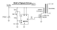
For example, in this flyback driver circuit, would it work to replace the MOSFET with a different transistor? and if so, would a 2N3055 work?
thanks!
would the same go for IGBTs, or are they completely different?
It depends on the circuit. Sometimes you can just use an ordinary transistor in its place. It is likely to perform differently if it works at all. It is also possible that the component driving the mosfet would be damaged if a ‘normal’ bipolar transistor is used in its place.
I’ve found a lot of circuits that involve a MOSFET, but I don’t have any. Is there anything else I can use instead of one, or will I have to go out and buy one?